Perform a compression test in order to determine the cylinder compression pressure. Use a compression test in order to diagnose lack of power, excessive oil consumption, or poor fuel economy.
Notice: This engine is equipped with an aluminum cylinder head. Allow the engine
to cool before removing spark plugs. Removing the spark plugs from an engine
at operating temperature may damage the spark plug threads in the cylinder
head. Also be sure to clean any dirt or debris from around spark plug holes
prior to removing spark plugs.
Important: The engine should be at room temperature.
- Verify that the battery is fully charged.

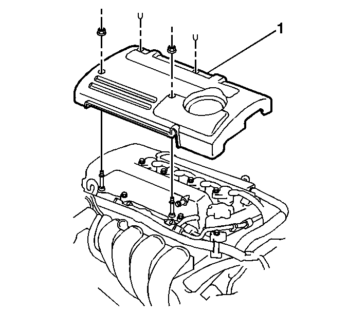
- Remove the 2 engine cover fasteners.
- Remove the 2 engine cover plastic retainers.
- Remove the engine cover (1) from the engine.

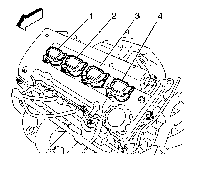
- Remove the four ignition coils (1-4) from the cylinder head cover.
- Remove the spark plugs from the cylinder head.

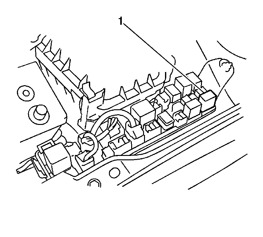
- Remove the EFI Main Relay (1) from the Fuse/Relay Block 1.

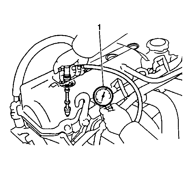
- Install a compression gage into a spark plug hole.
- Depress the clutch pedal (on vehicles that are equipped with a manual transmission).
- Depress the accelerator pedal to the floor for a wide open throttle.
- Crank the engine through four compression strokes for each cylinder being tested.
Important: The maximum allowable compression pressure difference between any two cylinders is 100 kPa (15 psi).
- Measure the highest pressure reading on the compression gage.
| • | The standard compression pressure is 1,300 kPa (218 psi). |
| • | The minimum allowable compression pressure is 1,000 kPa (145 psi). |
- Repeat the compression test procedures for the remaining three cylinders.
- Remove the compression gage from the engine.
- Install the four spark plugs.

- Install the four ignition coils (1-4) to the cylinder head cover.

- Position the engine cover (1) to the engine.
Notice: Refer to Fastener Notice in the Preface section.
- Install the 2 engine cover fasteners.
Tighten
Tighten the engine cover fasteners to 7 N·m (62 lb in).
- Install the 2 engine cover plastic retainers.

- Reconnect the EFI Main Relay (2) to the Fuse/Relay Block 1.
- Inspect for the following conditions:
| • | The pistons, piston rings and valves are operating normally if the cylinder compression pressure increases quickly and evenly to the compression standard (1,300 kPa [218 psi]). |
| • | The following actions indicate that the piston rings are faulty: |
| - | The cylinder compression is low on the first stroke. |
| - | The cylinder compression increases on the following strokes but does not reach the compression standard. |
| • | The following actions indicate that the valves are faulty: |
| - | The cylinder compression is low on the first stroke. |
| - | The cylinder compression does not increase on the following strokes. |


