GM Service Manual Online
For 1990-2009 cars only

Tools Required

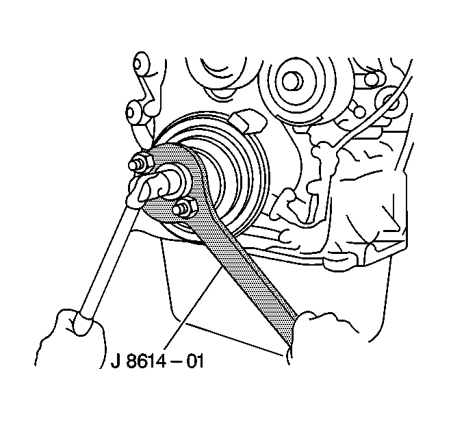
J 8614-01 Pinion Flange Holder

Removal Procedure


    Object Number: 244267  Size: SH
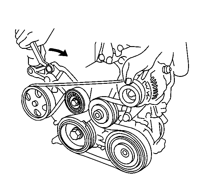
  1. Remove the accessory drive belt. Refer to Drive Belt Replacement .
  2. Remove the generator from the engine. Refer to Generator Replacement .
  3. Caution: Refer to Battery Disconnect Caution in the Preface section.

  4. Disconnect the negative battery cable.
  5. Drain the cooling system. Refer to Cooling System Draining and Filling .
  6. Install the engine support fixture. Refer to Engine Support Fixture .
  7. Remove the engine mount and engine mounting bracket. Refer to Engine Mount Replacement .
  8. Remove the cylinder head cover. Refer to Cylinder Head Cover Replacement .

  9. Object Number: 234138  Size: SH
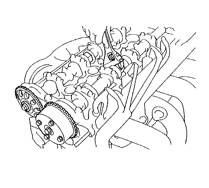
  10. Set the number 1 piston to the top dead center (TDC) position.
  11. Align the camshaft timing sprockets.
  12. Disconnect the power steering oil pressure switch connector.
  13. Raise and properly support the vehicle. Refer to Lifting and Jacking the Vehicle .
  14. Remove the right engine splash shield. Refer to Engine Splash Shield Replacement - Left Side .

  15. Object Number: 236875  Size: SH
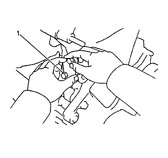
  16. Remove the 2 power steering pump through bolts and the nuts (1).
  17. Remove the power steering pump from the mounting surface.
  18. Move the pump to the side.


    Object Number: 234153  Size: SH
  19. Remove the crankshaft pulley retaining bolt using J 8614-01 .
  20. Remove the crankshaft pulley.

  21. Object Number: 234378  Size: SH
  22. Remove the following components:
  23. • The crankshaft position sensor bolt (5)
    • The sensor
  24. Lower the vehicle.
  25. Remove the following components from the mounting surface:
  26. • The drive belt tensioner bolt
    • The drive belt tensioner nut
    • The drive belt tensioner

    Object Number: 234178  Size: SH
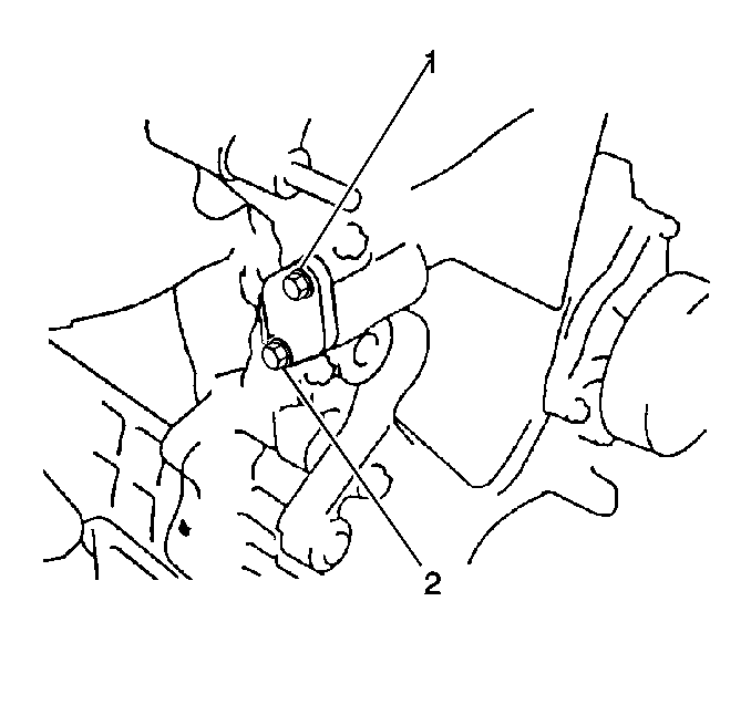
  27. Remove the timing chain tensioner bolts (1, 2).
  28. Remove the timing chain tensioner.

  29. Object Number: 1492166  Size: SH
  30. Remove the following fasteners:
  31. • The timing chain cover bolts (2-5)
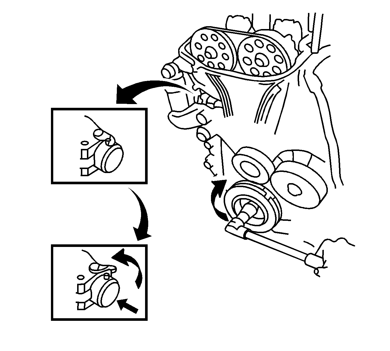
    • The timing chain cover nuts (1)
  32. Remove the timing chain cover.

  33. Object Number: 234359  Size: SH
  34. Remove the crankshaft sensor reluctor (1).

  35. Object Number: 625486  Size: SH
  36. Remove the following components:
  37. • The timing chain dampener bolt (1)
    • The timing chain dampener
    • The timing chain shoe bolts (2)
    • The timing chain shoe

    Object Number: 234188  Size: SH
  38. Remove the following components:
  39. • The crankshaft sprocket
    • The timing chain
  40. Remove the three bolts from the front camshaft bearing cap.
  41. Remove the front camshaft bearing cap in order to access the oil passage to the camshaft position (CMP) actuator.

  42. Object Number: 652440  Size: SH
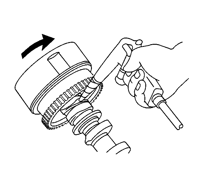
  43. Ensure that the CMP actuator will not turn.
  44. Apply air pressure of approximately 100 kPa (14 psi) to the advance passage of the camshaft.
  45. Turn the CMP actuator to the advanced angle side by hand.
  46. Rotate the actuator back and forth through the advanced positions to ensure 21 degrees of movement.
  47. Remove the air pressure and turn the CMP actuator back to the minimum advanced angle position to lock it.
  48. Replace the CMP actuator if the following conditions exist:
  49. • CMP actuator does not lock with air pressure removed.
    • CMP actuator does not unlock with air pressure applied.
    • CMP actuator does not rotate smoothly through the advanced positions.
    • CMP actuator does not rotate completely through the advance positions.
  50. Install the front camshaft bearing cap.
  51. Notice: Refer to Fastener Notice in the Preface section.

  52. Install the front camshaft bearing cap bolts.
  53. Tighten
    Tighten the camshaft bearing cap bolts to 23 N·m (17 lb ft).

Installation Procedure


    Object Number: 625497  Size: SH
  1. Use a wrench in order to align the camshaft timing marks.
  2. Be sure to place the wrench on the hexagonal portion of the camshafts.
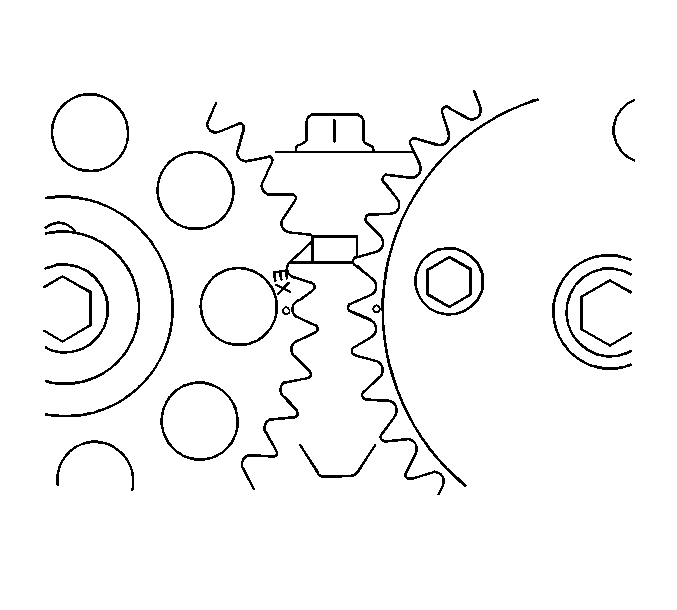

    Object Number: 625505  Size: SH
  3. Turn the camshafts in order to align the timing marks.
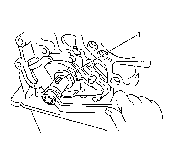
  4. Object Number: 234304  Size: SH
  5. Temporarily install the crankshaft bolt.
  6. Turn the crankshaft until the crankshaft keyway (1) faces upward.
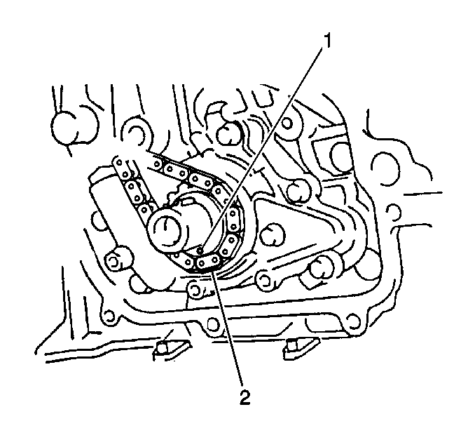
  7. Object Number: 234322  Size: SH
  8. Install the following components:
  9. • The timing chain (2)
    • Install the timing chain on the crankshaft timing sprocket with the yellow color link aligned with the mark on the crankshaft timing sprocket.
    • The crankshaft timing sprocket

    Notice: Refer to Fastener Notice in the Preface section.

    Object Number: 234315  Size: SH
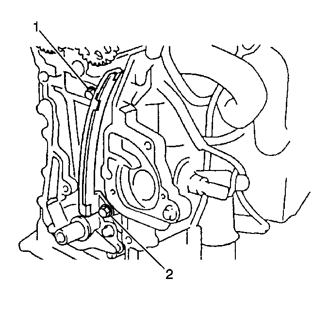
  10. Install the timing chain shoe. Secure the timing chain shoe using 2 bolts (1, 2).
  11. Tighten
    Tighten the timing chain shoe bolts to 10 N·m (89 lb in).

    Object Number: 1696396  Size: SH
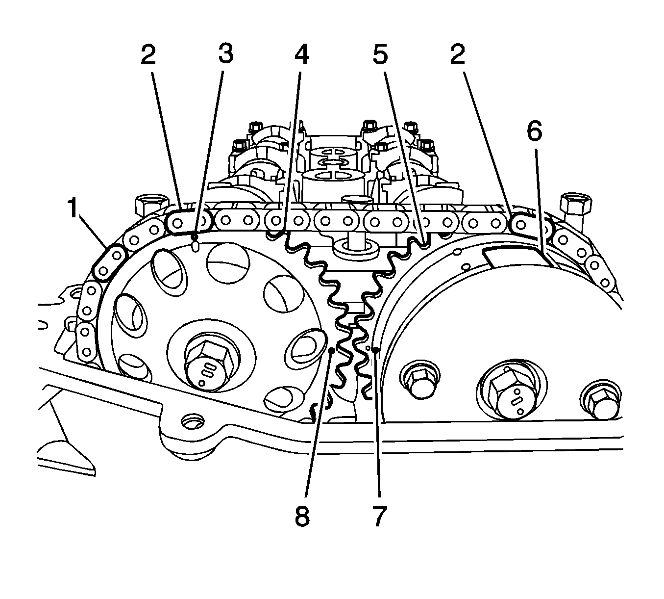
  12. Install the timing chain (1) onto the exhaust camshaft sprocket  (4) and the intake camshaft sprockets (5).
  13. Ensure that the yellow timing chain links  (2) are aligned with the timing marks (3), (6). The intake cam phaser mark  (7) should be at the 9 o'clock position and the "Ex" timing mark  (8) on the exhaust camshaft sprocket  (4) should be at the 3 o'clock position. The colored links (2) will line up around the 12 o'clock position with the double dots  (3) on the exhaust sprocket and the line  (6) on the cam phaser body.

    Object Number: 625486  Size: SH
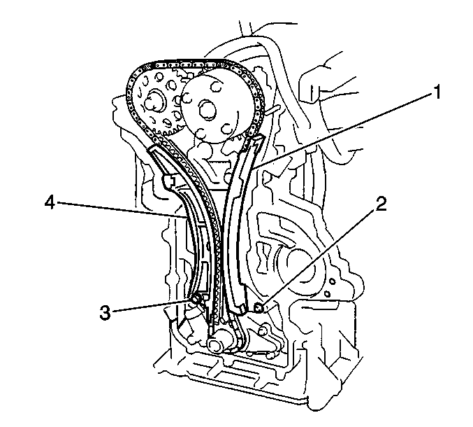
  14. Install the timing chain dampener. Secure the timing chain dampener using 1 bolt (1).
  15. Tighten
    Tighten the timing chain dampener bolt to 18 N·m (14 lb ft).

    Object Number: 234359  Size: SH
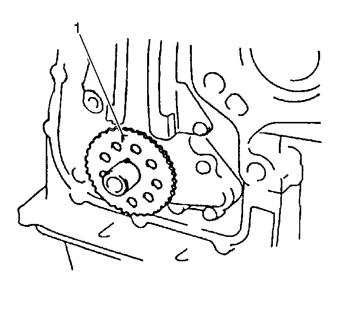
  16. Install the crankshaft sensor reluctor (1) onto the crankshaft. Insure that the F on the reluctor is facing outward.
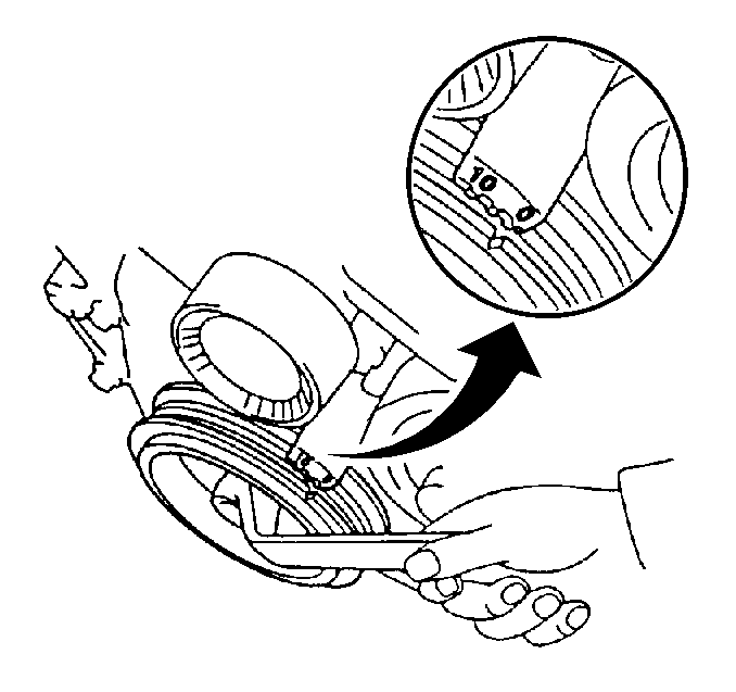
  17. Unlock the intake camshaft actuator locking pin. Refer to Camshaft Position Actuator Locking Pin Adjustment .
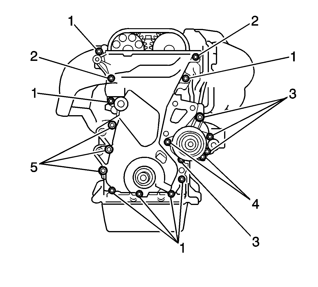
  18. Apply a continuous bead of GM P/N 12346240 (Canadian P/N 10953493) or an equivalent to the timing chain cover mating surface.
  19. Object Number: 1492166  Size: SH
  20. Install the timing chain cover water pump and o-ring.
  21. Install the following fasteners and uniformly tighten the bolts and nuts in several steps in order to secure the cover:

    • Sixteen bolts (2 -- 5)
    • Two nuts (1)

    Tighten

       • 

    Tighten the timing chain cover bolts (1) (25 mm (0.98 in) length) to 13 N·m (10 lb in).

       • 

    Tighten the timing chain cover bolts (3) (35 mm (1.38 in) length) to 11 N·m (8 lb ft).

       • 

    Tighten the timing chain cover bolts (4) (30 mm (0.79 in) length) to 9 N·m (80 lb in).

       • 

    Tighten the timing chain cover bolts (5) (45 mm (1.77 in) length) to 19 N·m (14 lb ft).

       • 

    Tighten the timing chain cover nuts (1) to 10 N·m (89 lb in).


    Object Number: 234392  Size: SH
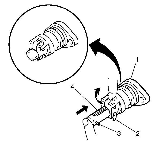
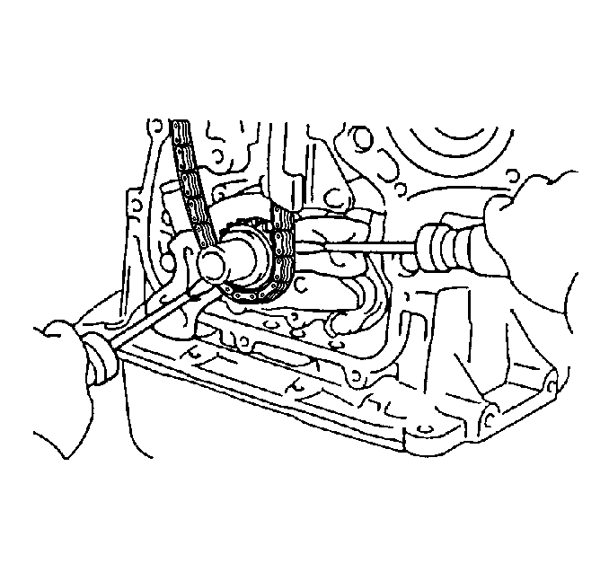
  22. Use the following steps in order to install the timing chain tensioner:
  23. 13.1. Fully depress the plunger (4).
    13.2. Apply the hook (2) to the pin (3).
    13.3. Install the timing chain tensioner.

    Object Number: 234394  Size: SH
  24. Install the timing chain tensioner. Secure the timing chain tensioner using 2 bolts (1).
  25. Tighten
    Tighten the timing chain tensioner bolts to 10 N·m (89 lb in).
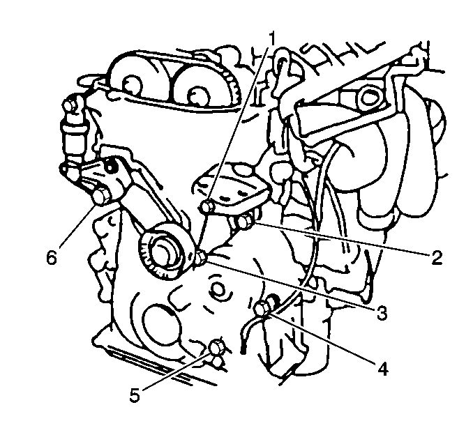

    Object Number: 234378  Size: SH
  26. Install the right side engine mounting bracket. Secure the bracket using 3 bolts.
  27. Tighten
    Tighten the engine mounting bracket bolts to 54 N·m (40 lb ft).

  28. Install the drive belt tensioner. Secure the tensioner using 1 bolt and one nut.
  29. Tighten

        • Tighten the bolt to 69 N·m (51 lb ft).
        • Tighten the nut to 29 N·m (21 lb ft).
  30. Raise the vehicle. Support the vehicle. Refer to Lifting and Jacking the Vehicle .
  31. Install the crankshaft position sensor. Secure the sensor using 1 bolt (5).
  32. Tighten
    Tighten the crankshaft position sensor bolt to 12 N·m (106 lb in).
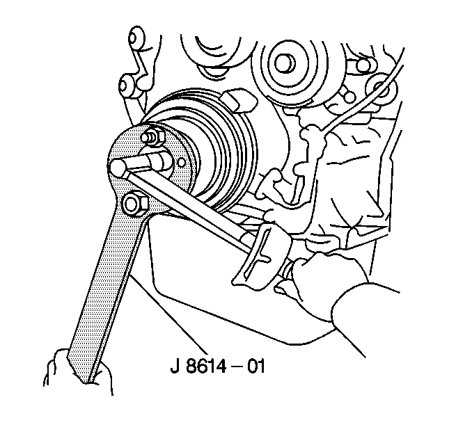

    Object Number: 234382  Size: SH
  33. Install the crankshaft pulley. Secure the crankshaft pulley using 1 bolt.
  34. Tighten
    Tighten the crankshaft pulley to 142 N·m (105 lb ft).
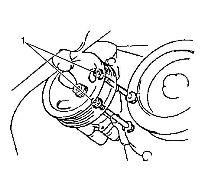

    Object Number: 236875  Size: SH
  35. Install the power steering pump.
  36. Use the following fasteners in order to secure the power steering pump:
  37. • Two bolts (1)
    • Two nuts

    Tighten
    Tighten the power steering pump bolts to 37 N·m (27 lb ft).

  38. Install the right engine splash shield. Refer to Engine Splash Shield Replacement - Left Side .
  39. Lower the vehicle.
  40. Connect the power steering oil pressure switch connector.
  41. Object Number: 234400  Size: SH
  42. Rotate the crankshaft clockwise 1 revolution. Ensure that the plunger on the timing chain tensioner has released.
  43. Complete the following steps if the plunger does not release:

    • Use a screwdriver or your finger in order to press the timing chain dampener into the timing chain tensioner.
    • Release the hook from the pin.
    • Verify proper timing chain alignment after the plunger has released.
  44. Install the cylinder head cover.
  45. Install the engine mount. Refer to Engine Mount Replacement .
  46. Remove the engine support fixture.
  47. Install the generator. Refer to Generator Replacement .
  48. Fill the cooling system. Refer to Cooling System Draining and Filling .
  49. Connect the negative battery cable.
  50. Tighten
    Tighten the battery cable bolt to 15 N·m (11 lb ft).