Brake Shoe Replacement FWD
Removal Procedure

Caution: Avoid taking the following actions when you service wheel brake parts:
| • | Do not grind brake linings. |
| • | Do not sand brake linings. |
| • | Do not clean wheel brake parts with a dry brush or with compressed air. |
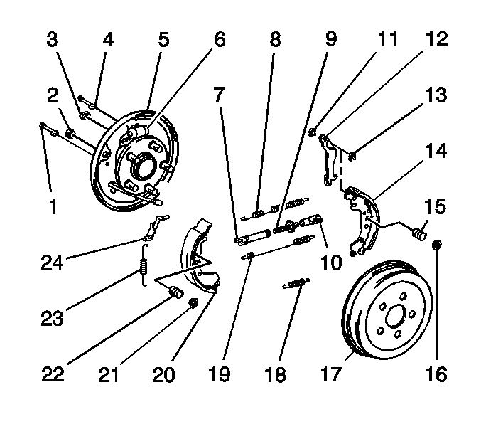
- Remove the drum (17). Refer to
Brake Drum Replacement
.
- Remove the upper return spring (8).
- Remove the lower return spring (19).
- Remove the following components from the front shoe (20):
| • | The hold-down spring cup (21) |
| • | The hold-down spring (22) |
- Remove the anchor spring (18).
- Remove the front shoe with the adjuster lever (24)
- Remove the adjuster lever and the adjuster spring (23) from the front shoe.
- Remove the following components from the rear shoe (14):
| • | The hold-down spring cup (16) |
| • | The hold-down spring (15) |
- Disconnect the park brake cable from the park brake lever (12).
- Remove the rear shoe.
- Remove the following components:
| • | The 2 C-shaped park brake lever washers (11,13) |
| • | The adjuster strut (7,9,10) |
- Separate the adjuster strut components.
Inspection Procedure

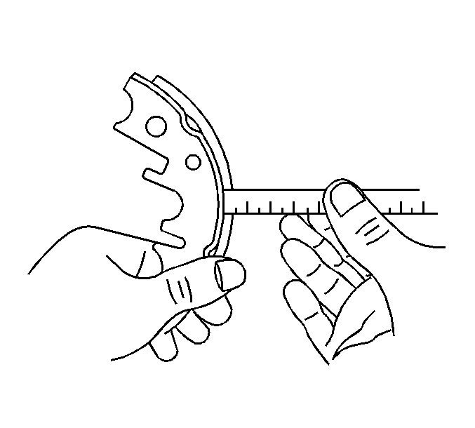
- Measure the brake shoe lining thickness.
Specification
The minimum shoe lining thickness is 1.00 mm (0.039 in).
- If the shoe lining is less than the specification, replace the brake shoes.
- Inspect the drum brake hardware. Refer to
Drum Brake Hardware Inspection
.
- Inspect the drum brake adjusting hardware. Refer to
Drum Brake Adjusting Hardware Inspection
.
Installation Procedure

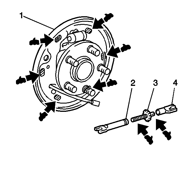
- Apply Lubriplate® Lubricant, GM P/N 1050109, Canadian P/N 5264008, or the equivalent, to the metal contact points on the backing plate (1) and the adjuster strut (3).
- Assemble the adjuster strut (2,3,4).

- Install the following components:
| • | The adjuster strut (7,9,10) |
| • | The park brake lever (12) |
| • | The 2 C-shaped park brake lever washers (11,13) |
- Connect the park brake cable to the park brake lever.
- Install the following components to the rear shoe:
| • | The hold-down spring (15) |
| • | The hold-down spring cup (16) |
- Install the adjuster lever (24) and the adjuster spring (23) to the front shoe (20).
- Install the front shoe.
- Install the anchor spring (18).
- Install the following components to the front shoe:
| • | The hold-down spring (22) |
| • | The hold-down spring cup (21) |
- Install the lower return spring (19).
- Install the upper return spring (8).
- Adjust the drum brake if necessary. Refer to
Drum Brake Adjustment
.
- Install the drum (17). Refer to
Brake Drum Replacement
.


