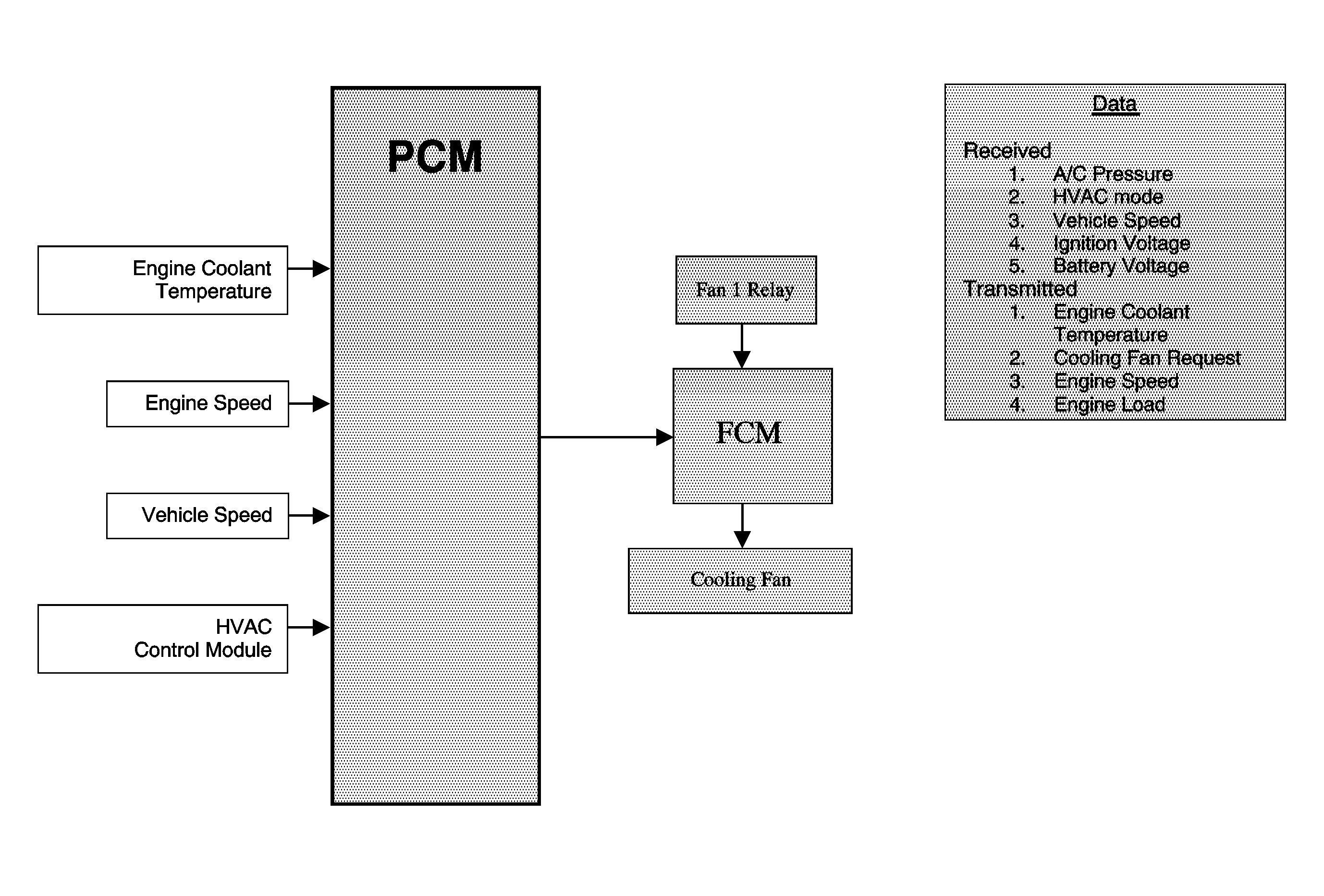
Single Fan - 1.8L (RPO-LAY)

The engine cooling fan system consists of an electric cooling fan, a fan relay, and a fan control module (FCM). The fan 1 relay provides power to the FCM. The FCM energizes the fan and controls fan speed according to instructions received from the powertrain control module (PCM). The PCM determines the desired fan speed according to input from various sensors and systems. The cooling fan and fan relay receive battery positive voltage from the underhood fuse block. The ground path is provided at G102.
Sensor Inputs to the PCM | Cooling Fan Control Module Response - Fan Speed |
|---|---|
Engine Coolant Temperature Increases | Increases |
Engine Coolant Temperature Decreases | Decreases |
Engine Speed Increases | Increases |
Engine Speed Decreases | Decreases |
Vehicle Speed Increases | Decreases |
Vehicle Speed Decreases | Increases |
A/C Refrigerant Pressure Increases | Increases |
A/C Refrigerant Pressure Decreases | Decreases |
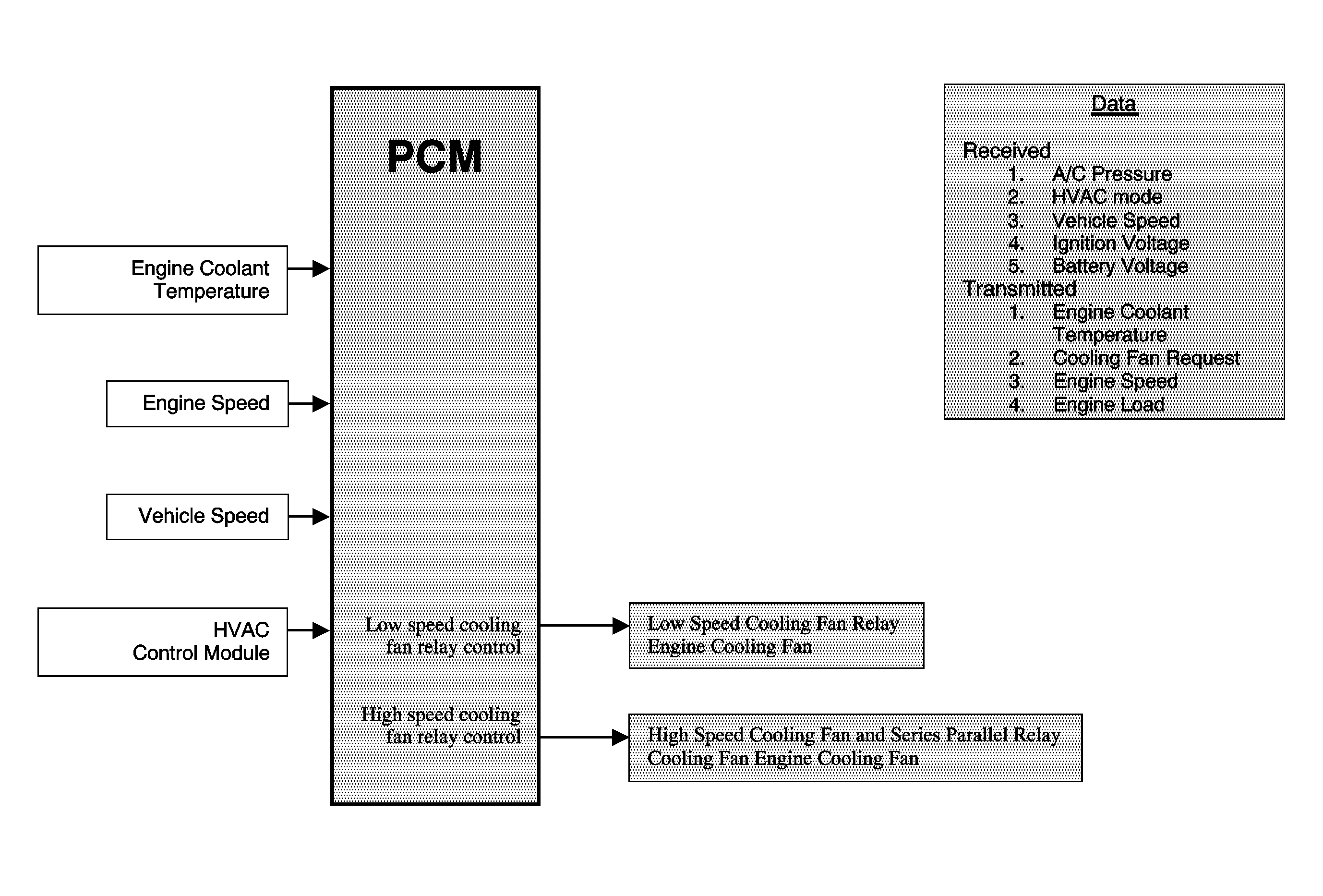
Dual Fans - 2.4L (RPO-LAX)

The engine cooling fan system consists of 2 electrical cooling fans and 3 fan relays. The relays are arranged in a series parallel (S/P) configuration that allows the powertrian control module (PCM) to operate both fans together at low or high speeds, depending on cooling requirements. The cooling fans and fan relays receive battery positive voltage from the underhood fuse block. The ground path is provided at G102.
In low speed operation, the PCM applies ground to the coil side of the low speed fan relay 3. This energizes the coil and applies voltage directly to the auxiliary cooling fan through the switch side of the low relay 3. The fan is connected in series to the main cooling fan through the de-energized S/P fan control relay 2. The series circuit operates both fans at low speed.
In high speed operation, the PCM applies a ground to the coil side of the low speed fan relay 3, the fan control relay 2, and the high speed fan relay 1. When energized, the high speed fan relay 1 applies voltage directly to the main cooling fan through the switch side of the relay. Simultaneously, the low speed fan relay 3 and the fan control relay 2 provide ignition voltage and a direct path to ground for the auxiliary cooling fan. With both fans connected in a parallel circuit, each fan receives full voltage and operates at high speed.
