For 1990-2009 cars only
Removal Procedure
- Release the fuel pressure. Refer to Fuel Pressure Relief.
- Disconnect the fuel pipe from the fuel rail.
- Disconnect the EVAP hose from the EVAP canister solenoid valve.
- Drain the engine coolant. Refer to Cooling System Draining and Filling.
- Remove the air cleaner assembly. Refer to Air Cleaner Assembly Replacement.
- Remove the battery and tray. Refer to Battery Tray Replacement.
- Remove the fuse box bolts.
- Discharge the A/C system, if equipped. Refer to Refrigerant Recovery and Recharging.
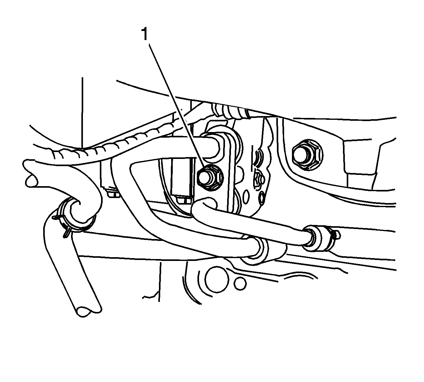
- Remove the A/C inlet/outlet pipe bolt (1) from the A/C compressor.
- Drain the power steering oil if equipped. Refer to Power Steering Pump Replacement.
- Remove the power steering pump pressure line union nut. Refer to Power Steering Pump Replacement.
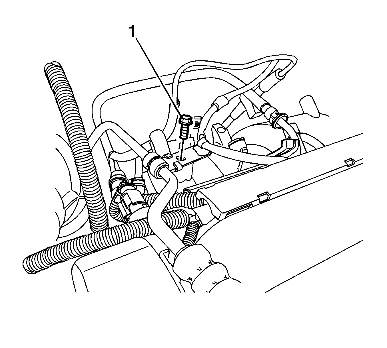
- Remove the power steering pressure pipe retaining clamp bolt (1) from the intake manifold.
- Disconnect the power steering hose from the power steering pump.
- Disconnect the following:
- Disconnect the following:
- Disconnect the following
- Disconnect the following and pull the engine harness aside.
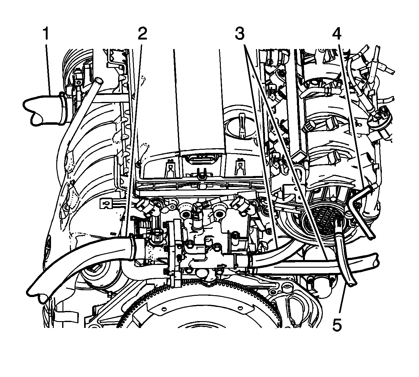
- Disconnect the coolant hose (1) from water pump.
- Disconnect the coolant hose (2) from the thermostat housing.
- Disconnect the heater core coolant inlet/outlet hoses (3) from the coolant distributor.
- Disconnect the ETC-to-coolant tank hose (4).
- Disconnect the brake boost hose (5) from the intake manifold.
- Remove and disconnect the cables and wiring harness related to the automatic transaxle.
- Disconnect the auto transaxle fluid cooler inlet/outlet hoses.
- Remove and disconnect the cables and wiring harness related to the manual transaxle.
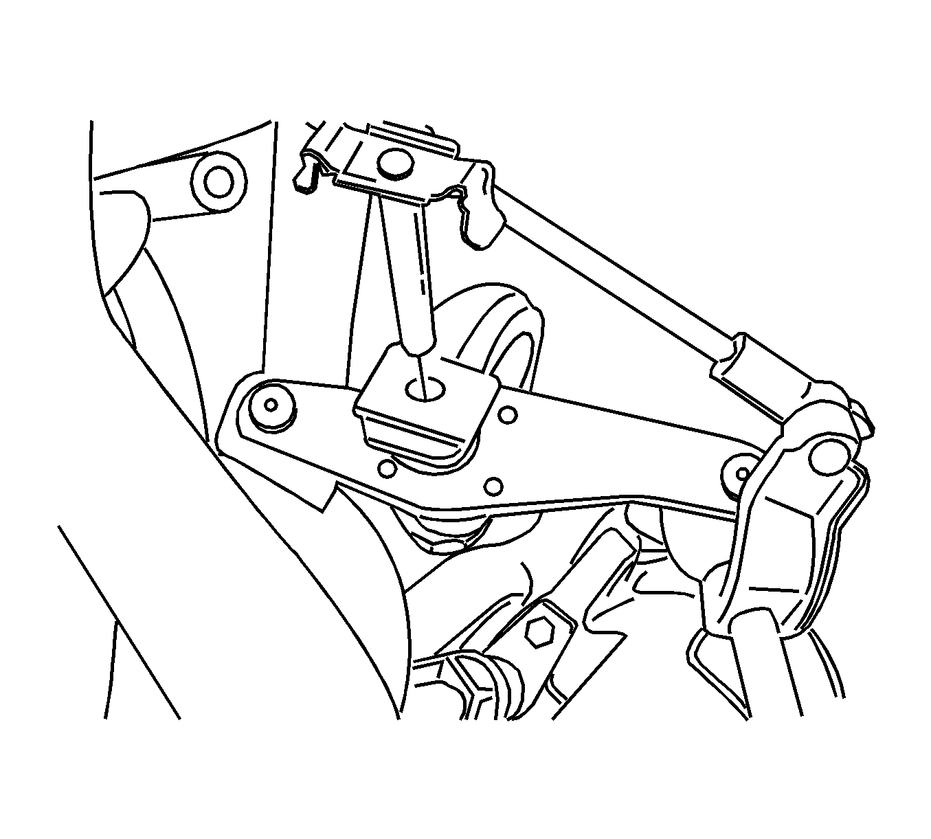
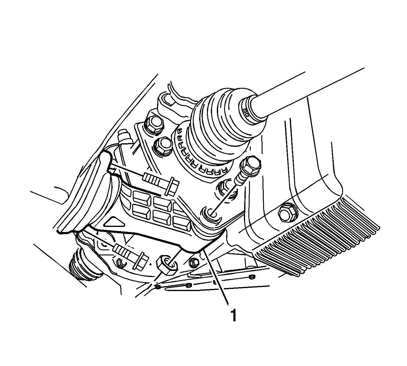
- Remove the reaction rod (1).
- Remove the exhaust front pipe. Refer to Front Pipe Replacement.
- Remove the drive axle shafts. Refer to Front Drive Axle Inner Shaft Replacement
- Raise the vehicle.
- Locatea suitable supporter under the vehicle engine and transaxle.
- Lower the vehicle until engine assembly is on the supporter.
- Remove the engine mount. Refer to Engine Mount Replacement.
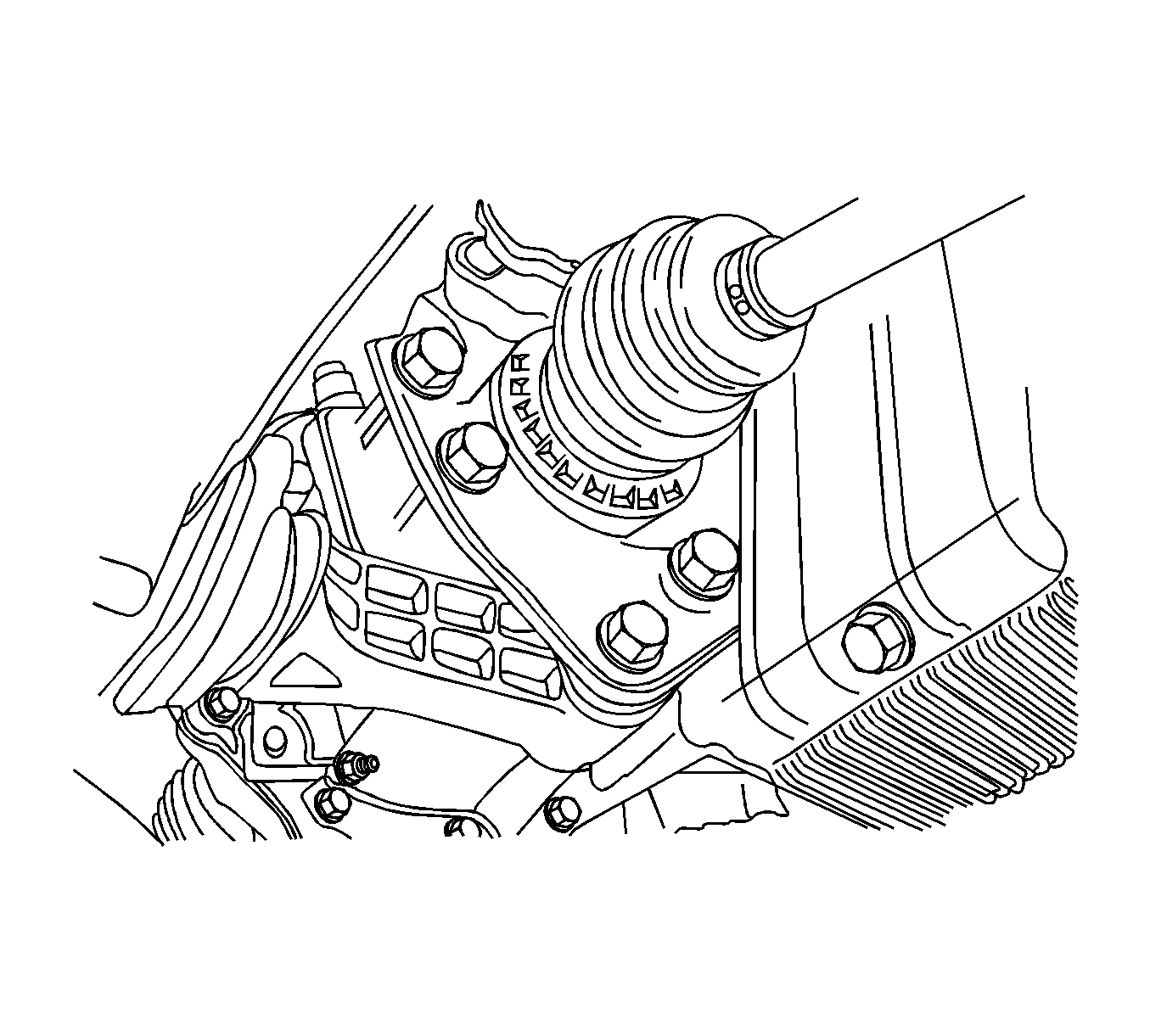
- Remove the transaxle mount.
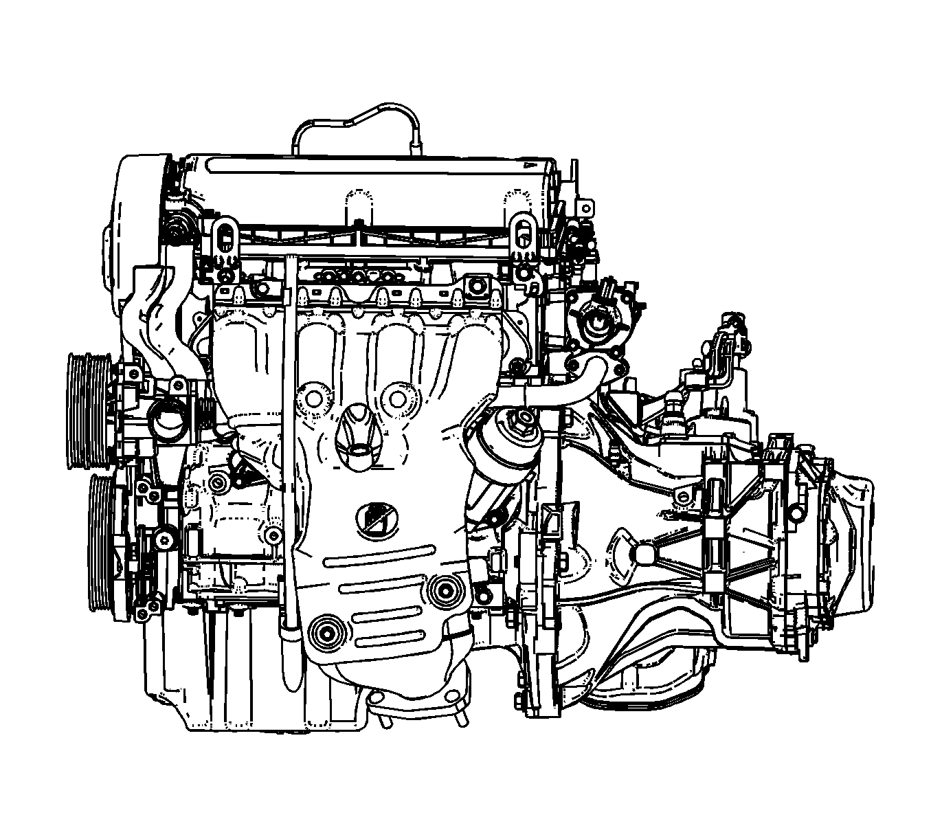
- Separate the engine and the transaxle.
| • | Oil switch wiring connector |
| • | A/C compressor connector |
| • | Intake air temperature sensor connector |
| • | A/C pressure sensor (ACP) connector |
| • | Cam position solenoid valve connector |
| • | Electric throttle controller (ETC) connector |
| • | Manifold air pressure (MAP) sensor connector |
| • | EVAP solenoid valve connector |
| • | Injector connectors |
| • | Ignition coil connector |
| • | Camshaft position sensor (CPS) connectors (right/left) |
| • | Coolant temperature sensor connector |
| • | Oxygen sensor connector |
| • | Ground bolt |
| • | Thermostat heater connector |
| • | Crankshaft position (CKP) sensor connector |
| • | Knock sensor connector |
| • | Alternator connector |
| • | Alternator B+ nut |
| • | Oil level switch connector, if equipped |
| • | Starter solenoid B+ nut |
| • | Ground tightening nut |
| • | Starter solenoid ground nut |
Installation Procedure
- Assemble the engine to the transaxle.
- Place the engine assembly on the supporter.
- Raise the vehicle.
- Locate the engine assembly with the supporter.
- Lower the vehicle.
- Install the engine mount. Refer to Engine Mount Replacement.
- Install the transaxle mount.
- Install the drive axle shafts. Refer to Front Drive Axle Inner Shaft Replacement.
- Install the exhaust front pipe. Refer to Front Pipe Replacement.
- Install the reaction rod (1).
- Install and connect the cables and wiring harness related to the automatic transaxle.
- Connect the auto transaxle fluid cooler inlet/outlet hoses.
- Install and connect the cables and wiring harness related to the manual transaxle.
- Connect the coolant hose (1) to the water pump.
- Connect the coolant hose (2) to the thermostat housing.
- Connect the heater core coolant inlet/outlet hoses (3) to the coolant distributor.
- Connect the ETC-to-coolant tank hose (4).
- Connect the brake boost hose (5) to the intake manifold.
- Position the engine harness and connect the following connectors.
- Connect the following:
- Connect the following:
- Install the power steering pump pressure line union nut.
- Install the power steering pressure pipe retaining clamp bolt (1) to the intake manifold.
- Connect the power steering hose to the power steering pump.
- Install the A/C inlet/outlet pipe bolt (1) from the A/C compressor if equipped.
- Charge the A/C system. Refer to Refrigerant Recovery and Recharging.
- Install the fuse box bolts.
- Install the battery and tray. Refer to Battery Tray Replacement.
- Install the air cleaner assembly. Refer to Air Cleaner Assembly Replacement.
- Connect the fuel pipe to the fuel rail.
- Connect the EVAP hose to the EVAP canister solenoid valve.



Caution: Refer to Fastener Caution in the Preface section.
| • | Crankshaft position (CKP) sensor connector |
| • | Knock sensor connector |
| • | Alternator connector |
| • | Alternator B+ nut |
| • | Oil level switch connector, if equipped |
| • | Starter solenoid B+ nut |
| • | Ground nut |
| • | Starter solenoid ground nut |
Tighten
| • | Tighten the alternator B+ nut to 15 N·m (11 lb ft). |
| • | Tighten the starter solenoid B+ nut to 10.5 N·m (7.7 lb ft). |
| • | Tighten the ground nut to 12 N·m (8.8 lb ft). |
| • | Tighten the starter solenoid ground nut to 38 N·m (28 lb ft). |
| • | Ignition coil connector |
| • | Camshaft position sensor (CPS) connectors (right/left) |
| • | Coolant temperature sensor connector |
| • | Oxygen sensor connector |
| • | Ground bolt |
Tighten
Tighten the ground bolt to 12 N·m (8.8 lb ft).
| • | Thermostat heater connector |
| • | Oil switch wiring connector |
| • | A/C compressor connector |


