For 1990-2009 cars only
Removal Procedure
- Disconnect the battery negative cable. Refer to Battery Negative Cable Disconnection and Connection.
- Disconnect the related sensor and actuator connector and pull engine wiring harness aside.
- Disconnect the oil switch wiring connector.
- Disconnect the A/C compressor connector.
- Disconnect the manifold air temperature (MAT) sensor connector.
- Disconnect the A/C pressure (ACP) sensor connector.
- Disconnect the CAM position solenoid valve connectors (right/left).
- Disconnect the manifold air pressure (MAP) sensor connector.
- Disconnect the EVAP canister purge solenoid valve connector.
- Disconnect the injectors connectors.
- Disconnect the ignition coil connector.
- Disconnect the camshaft position sensor (CPS) connectors (right/left).
- Remove the ignition coil. Refer to Ignition Coil Replacement.
- Detach the PCV clips from the PCV hose.
- Remove the PCV hose from the cylinder head cover.
- Remove the cylinder head cover bolts.
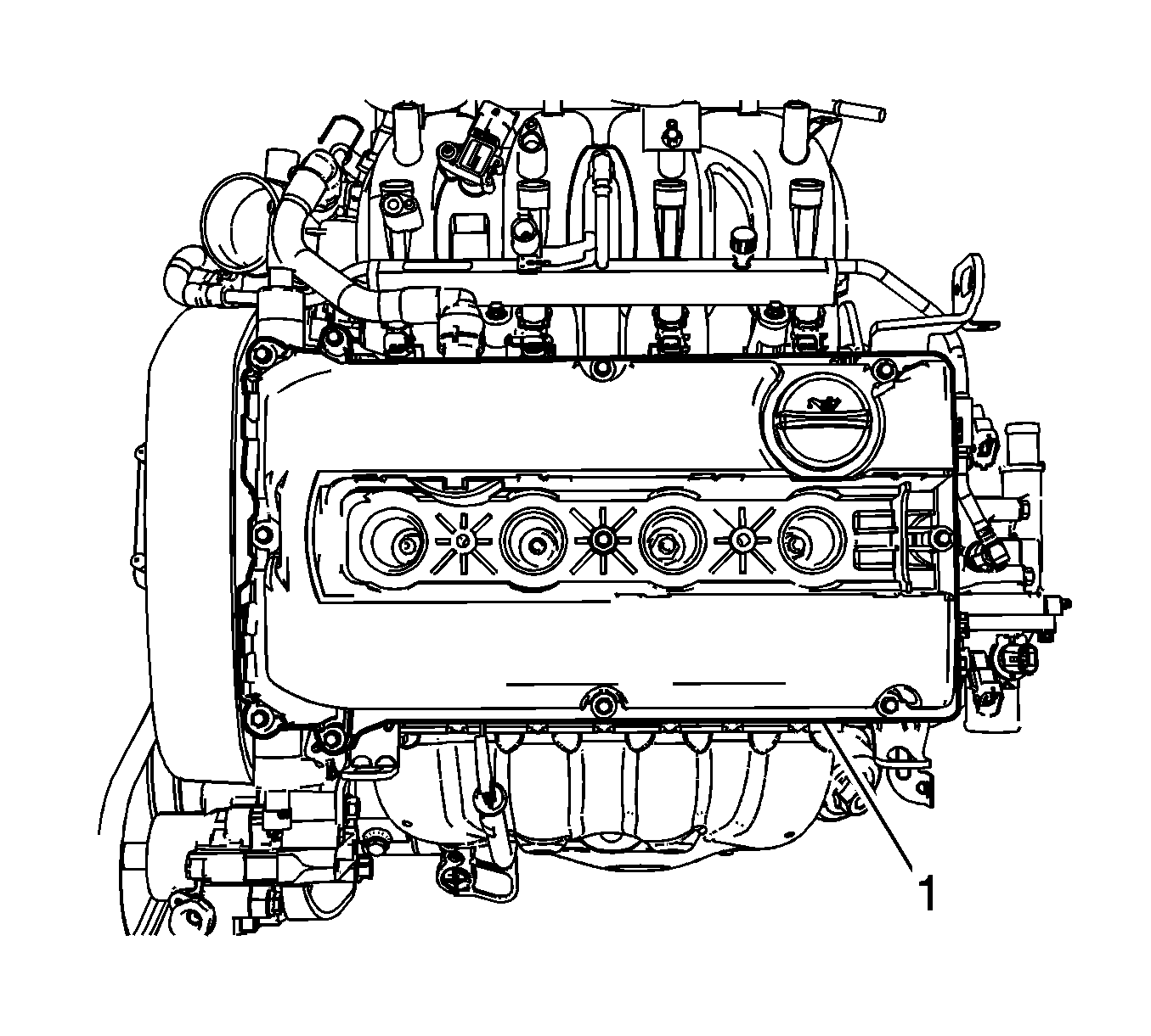
- Remove the cylinder head cover (1).
Warning: Refer to Battery Disconnect Warning in the Preface section.
Installation Procedure
- Install the cylinder head cover (1) with the gasket.
- Install the cylinder head cover bolts and tighten to 8 N·m (70.8 lb in).
- Install the PCV hose to the cylinder head cover.
- Attach the PCV clips to the PCV hose.
- Install the ignition coil. Refer to Ignition Coil Replacement.
- Position the engine wiring harness and connect the related sensor and actuator connector.
- Connect the oil switch wiring connector.
- Connect the A/C compressor connector.
- Connect the manifold air temperature (MAT) sensor connector.
- Connect the A/C pressure (ACP) sensor connector.
- Connect the CAM position solenoid valve connectors (right/left).
- Connect the manifold air pressure (MAP) sensor connector.
- Connect the EVAP canister purge solenoid valve connector.
- Connect the injector connectors.
- Connect the ignition coil connector.
- Connect the camshaft position sensor (CPS) connectors (right/left).
- Connect the battery negative cable. Refer to Battery Negative Cable Disconnection and Connection.
Note: Check and Confirm the damage or crack of the cylinder head gasket. If damaged or cracked, replace the new one.
Caution: Refer to Fastener Caution in the Preface section.
