For 1990-2009 cars only
Tools Required
J 21854-01 Pivot Pin Remover
Removal Procedure
- Disable the SIR system. Refer to SIR Disabling and Enabling in SIR.
- Remove the steering column from the vehicle. Refer to Steering Column Replacement .
- Remove the turn signal and multifunction switch assembly. Refer to Turn Signal Multifunction Switch Replacement .
- Remove the windshield wiper washer switch assembly. Refer to Windshield Wiper and Washer Switch Replacement .
- Remove the turn signal switch housing. Refer to Multifunction Turn Signal Switch Housing Replacement .
- Remove the tilt spring. Refer to Steering Column Tilt Spring Replacement .
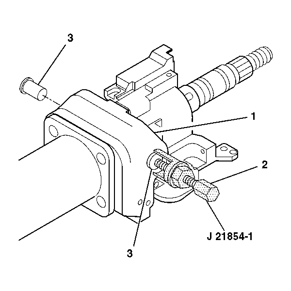
- Remove the 2 pivot pins (3) from the steering column tilt head assembly (1) using J 21854-01 .
- Verify the type of steering wheel position sensor before removal. Refer to Steering Wheel Position Sensor Centering .
- Remove the steering wheel position sensor and adapter and bearing assembly from the steering column jacket by pulling the assembly straight out.
- Remove the steering wheel position sensor from the clips in the adapter and bearing assembly.
- Install the tilt lever into the steering column tilt head assembly (1).
- Pull back on the tilt lever and at the same time pull the steering column tilt head assembly (1) down and away from the steering column.
- Remove the steering column tilt head assembly (1) with the steering shaft assembly (3) from the steering column jacket assembly (2).
- Remove the tilt lever.
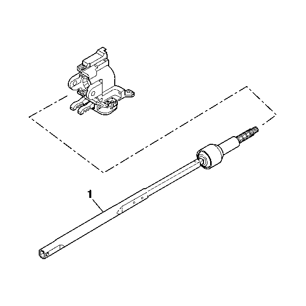
- Remove the steering shaft (1) from the steering column tilt head assembly.
Caution: Refer to SIR Caution in the Preface section.
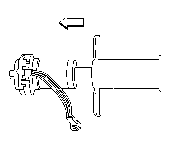
Important: Do not apply force to the steering wheel position sensor and the adapter and bearing assembly in a sideways direction.
If reusing the existing steering wheel position sensor, it MUST be centered before removal. A pin MUST be installed in the sensor before removal, failure to do so will cause sensor to be misaligned.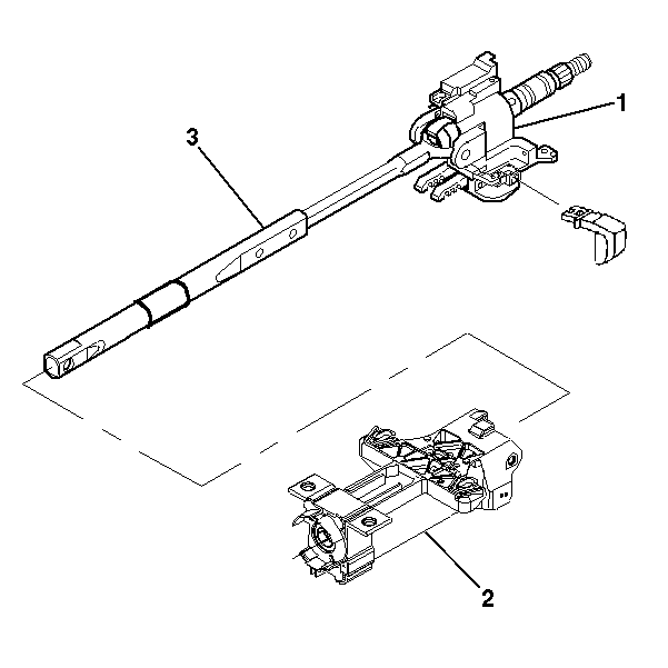
Installation Procedure
- Install the steering shaft (1) into the steering column tilt head assembly.
- Install the steering shaft (3) into the steering column tilt head assembly (1).
- Install the tilt head assembly (1) and the steering shaft (3) into the steering column jacket assembly (2).
- Align the steering column tilt head assembly with the pivot pin holes on the steering column jacket assembly.
- Lubricate the pivot pins with GM P/N 12346293 (Canadian P/N 992723).
- Stake the pins in 3 places.
- If reusing the existing steering wheel position sensor, verify the type of sensor you have before installing. Refer to Steering Wheel Position Sensor Centering .
- Install the steering wheel position sensor into the adapter and bearing assembly.
- Install the adapter and bearing assembly into the steering column jacket.
- Connect the steering wheel position sensor connector.
- Install the tilt spring assembly only. Refer to Steering Column Tilt Spring Replacement .
- Install the turn signal switch housing only. Refer to Multifunction Turn Signal Switch Housing Replacement .
- Install the turn signal and multifunction switch assembly only. Refer to Turn Signal Multifunction Switch Replacement .
- Install the windshield washer wiper switch assembly. Refer to Windshield Wiper and Washer Switch Replacement .
- Install the steering column to the vehicle. Refer to Steering Column Replacement .
- Enable the SIR system. Refer to SIR Disabling and Enabling in SIR.


Important: The steering wheel lock shoes teeth must be resting on the bar in the steering column jacket assembly.
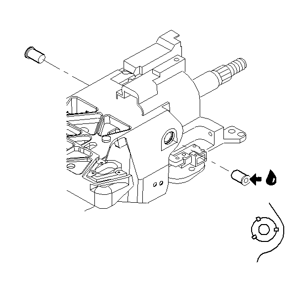
Install the 2 pivot pins into the steering column support assembly.

| 9.1. | Align the notches on the adapter and bearing assembly and the steering column jacket. |
| Important: Do not apply force to the steering wheel position sensor and the adapter and bearing assembly in a sideways direction. |
| 9.2. | Seat the adapter and bearing assembly into the steering column jacket. |
