GM Service Manual Online
For 1990-2009 cars only
Figure 1:

Module Power, Ground, Serial Data, and MIL
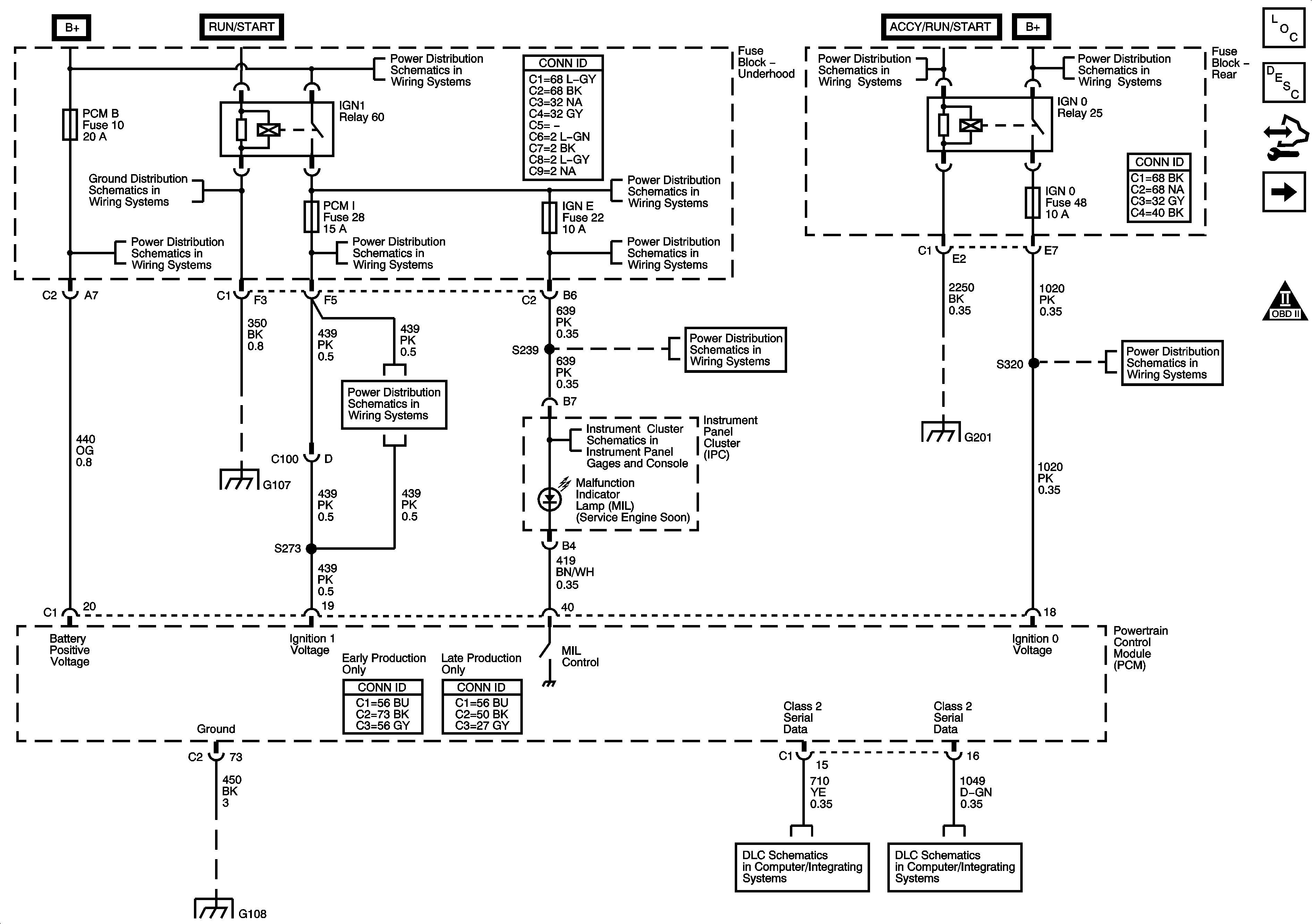

Object Number: 1614334  Size: FS
Master Electrical Component List
Powertrain Control Module Description
Control Module References
Fuse Block Underhood - Powertrain Relay
Engine Controls Schematic Icons
G104, G105 and G107
EAP, ECM, PCMB, TBC I, and TCM CNSTR Fuses
B+ Bus - Underhood Fuse Block - 1 of 2
AIR SOL and PCM I Fuses
BCK/UP, BTSI, IGN E, and TRLR BCK/UP Fuses
Ignition Switch - ACCY/RUN/START, RUN, START Bus Bars and IGNA1 Fuse
B+ Bus - Rear Fuse Block
G104, G105 and G107
AIR SOL and PCM I Fuses
BCK/UP, BTSI, IGN E, and TRLR BCK/UP Fuses
Power, Ground, Serial Data, and MIL
G201 - 1 of 2
4WD, BRK, FRT WPR, HVAC I, IGN 0, and TCM Fuses
G108
Power, Ground, Data Link Connector
SP 205
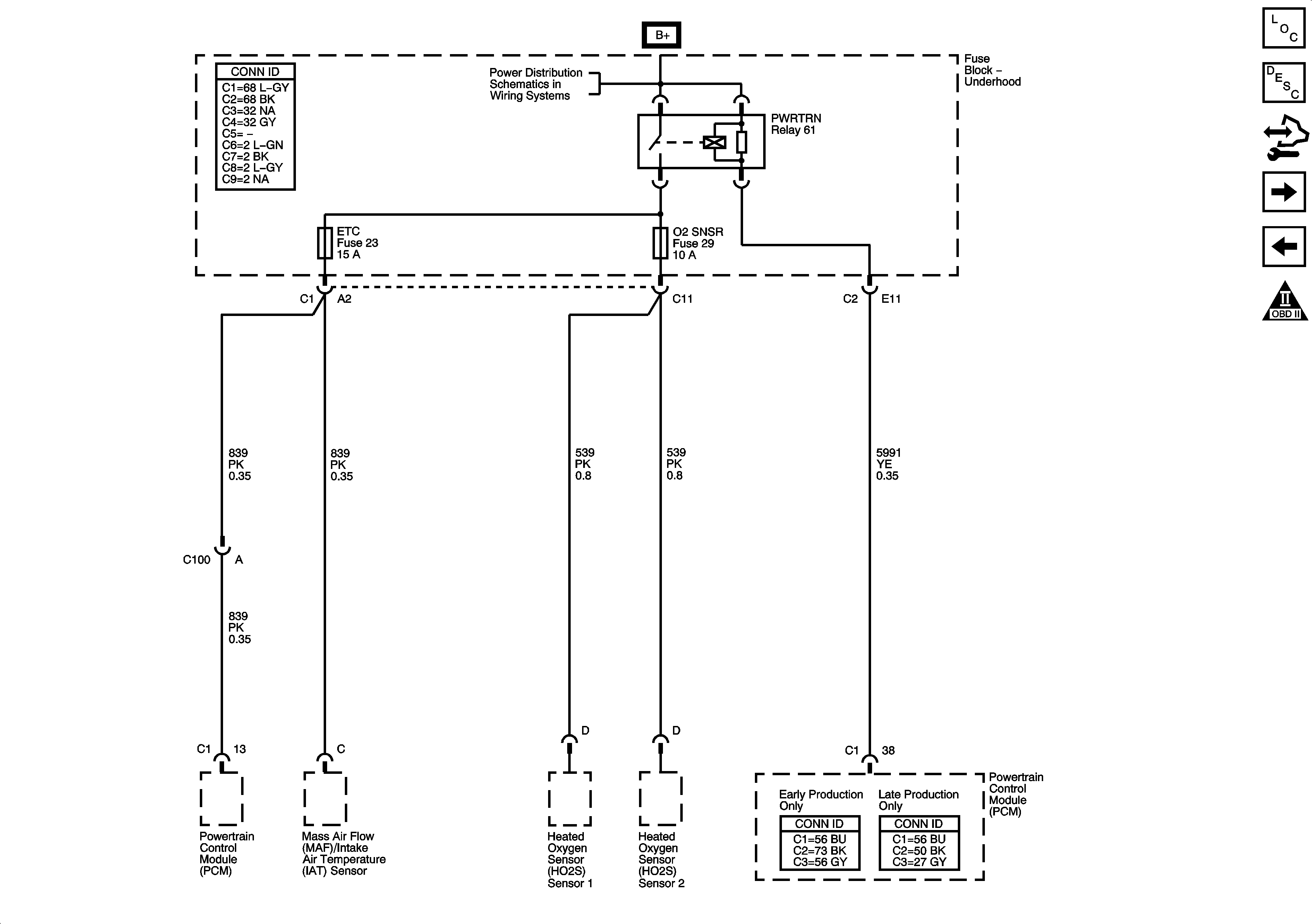
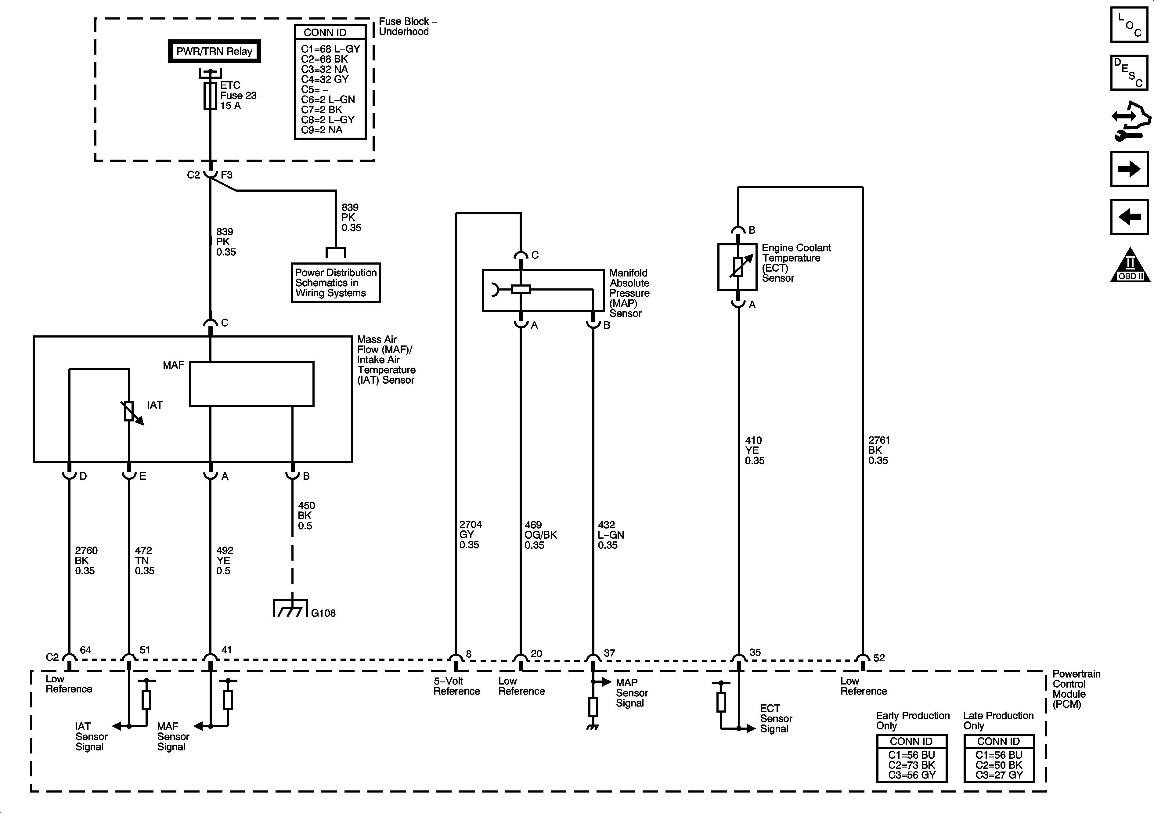
Figure 2:

Fuse Block - Underhood PWR/TRN Relay


Object Number: 1614335  Size: FS
Master Electrical Component List
Powertrain Control Module Description
Control Module References
Fuse Block Underhood - IGN 1 Relay
Module Power, Ground, Serial Data and MIL
Engine Controls Schematic Icons
B+ Bus - Underhood Fuse Block - 2 of 2
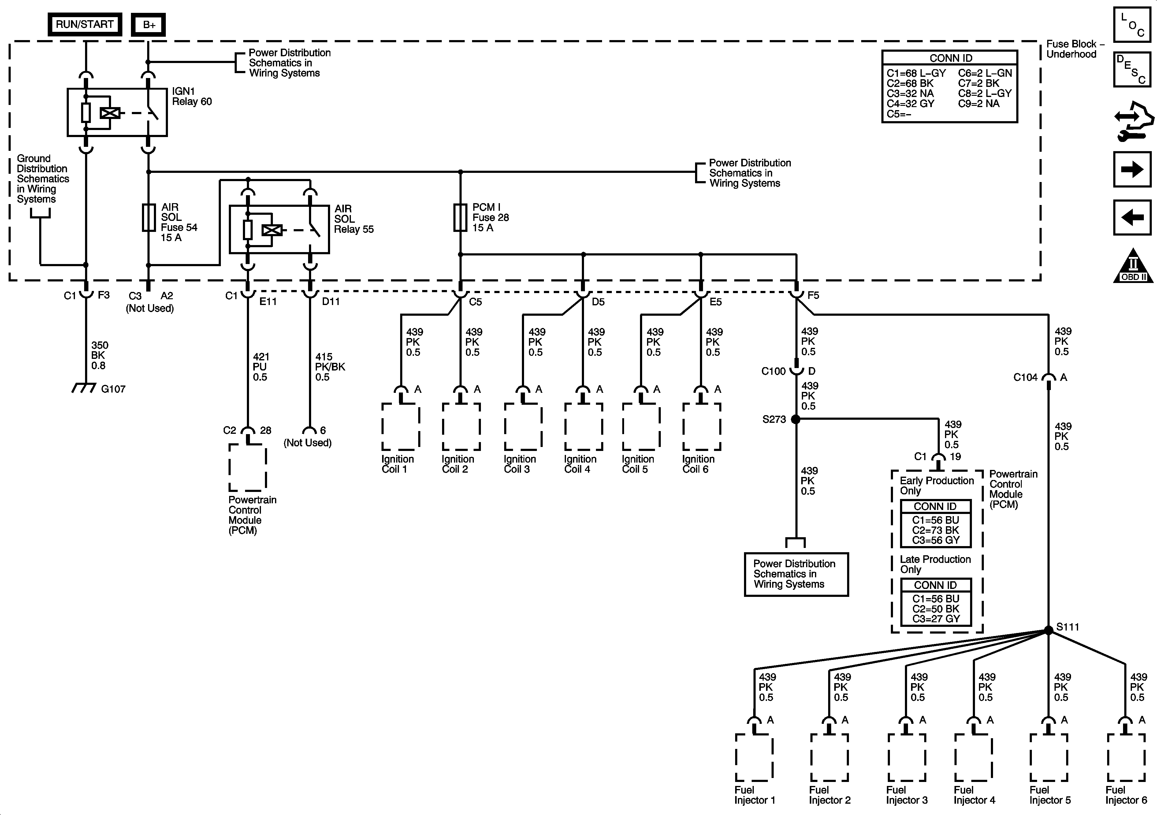
Figure 3:

Fuse Block - Underhood IGN1 Relay


Object Number: 1614336  Size: FS
Master Electrical Component List
Fuel System Description
Control Module References
5-Volt and Low Reference
Fuse Block Underhood - Powertrain Relay
Engine Controls Schematic Icons
G104, G105 and G107
B+ Bus - Underhood Fuse Block - 2 of 2
Pressure and Temperature Sensors
AIR SOL and PCM I Fuses
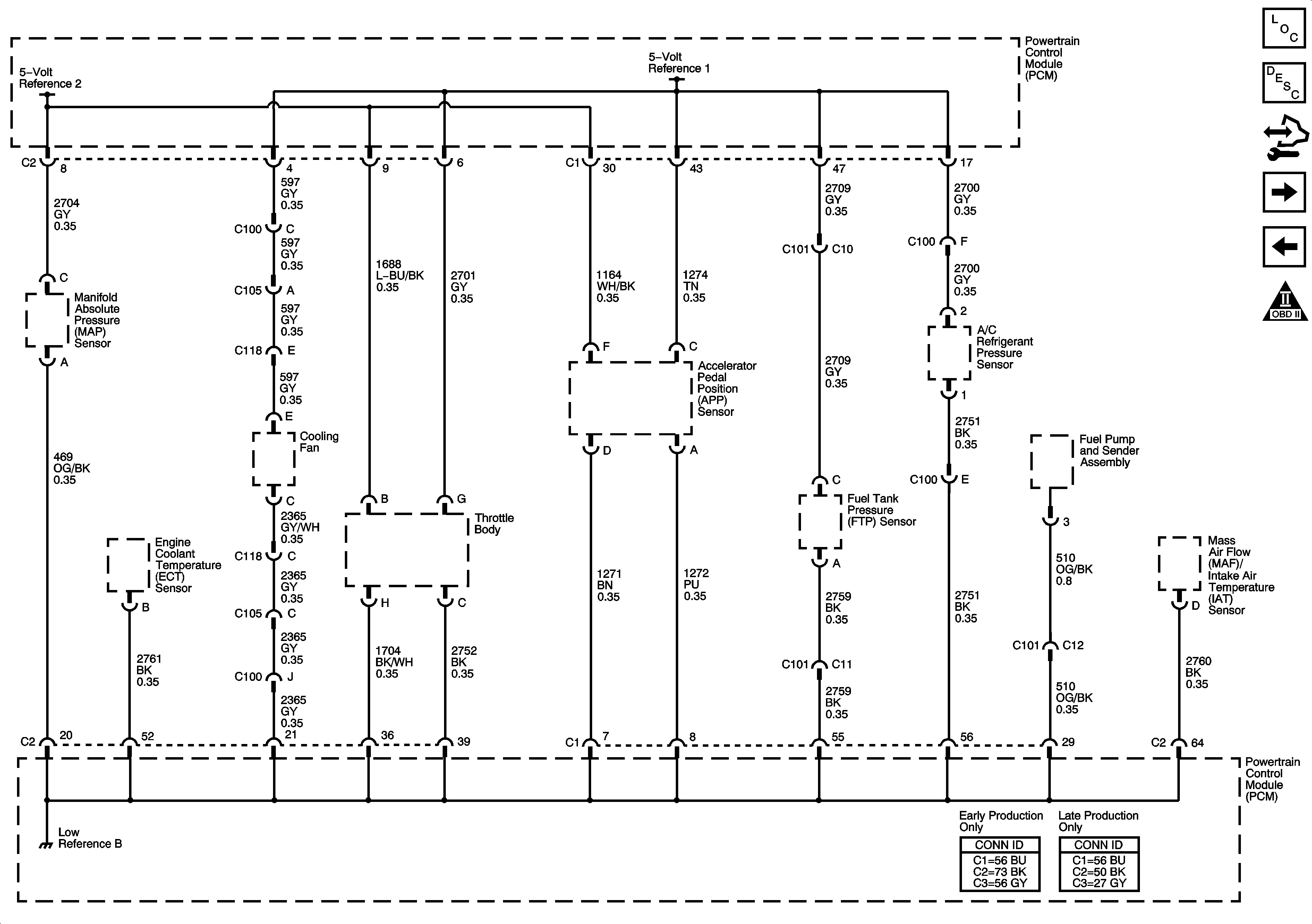
Figure 4:

5-Volt and Low Reference


Object Number: 1614338  Size: FS
Master Electrical Component List
Powertrain Control Module Description
Control Module References
Engine Data Sensors - Pressure and Temperature
Fuse Block Underhood - IGN 1 Relay
Engine Controls Schematic Icons
Figure 5:

Engine Data Sensors - Pressure and Temperature


Object Number: 1614340  Size: FS
Master Electrical Component List
Powertrain Control Module Description
Control Module References
Engine Data Sensors - Oxygen Sensors
5-Volt and Low Reference
Engine Controls Schematic Icons
Fuse Block Underhood - Powertrain Relay
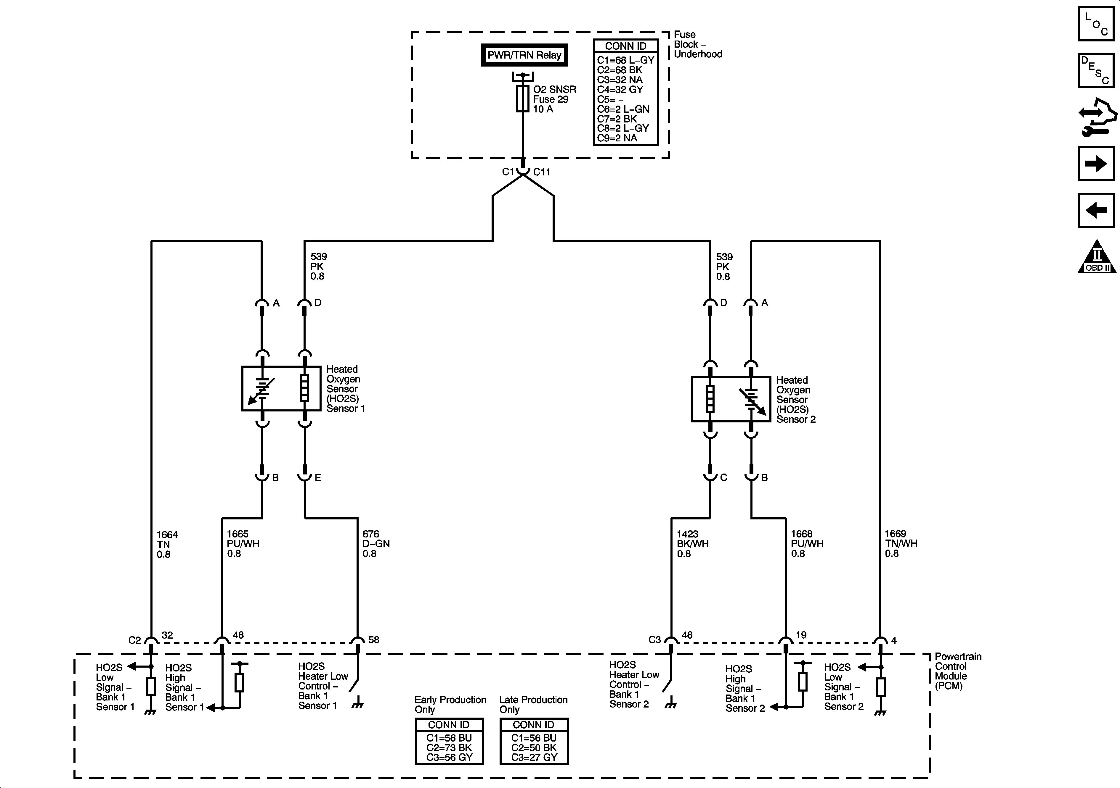
Figure 6:

Engine Data Sensors - Oxygen Sensors


Object Number: 1614342  Size: FS
Master Electrical Component List
Powertrain Control Module Description
Control Module References
Engine Data Sensors - Throttle Actuator Controls and VSS
Engine Data Sensors - Pressure and Temperature
Engine Controls Schematic Icons
Fuse Block Underhood - Powertrain Relay
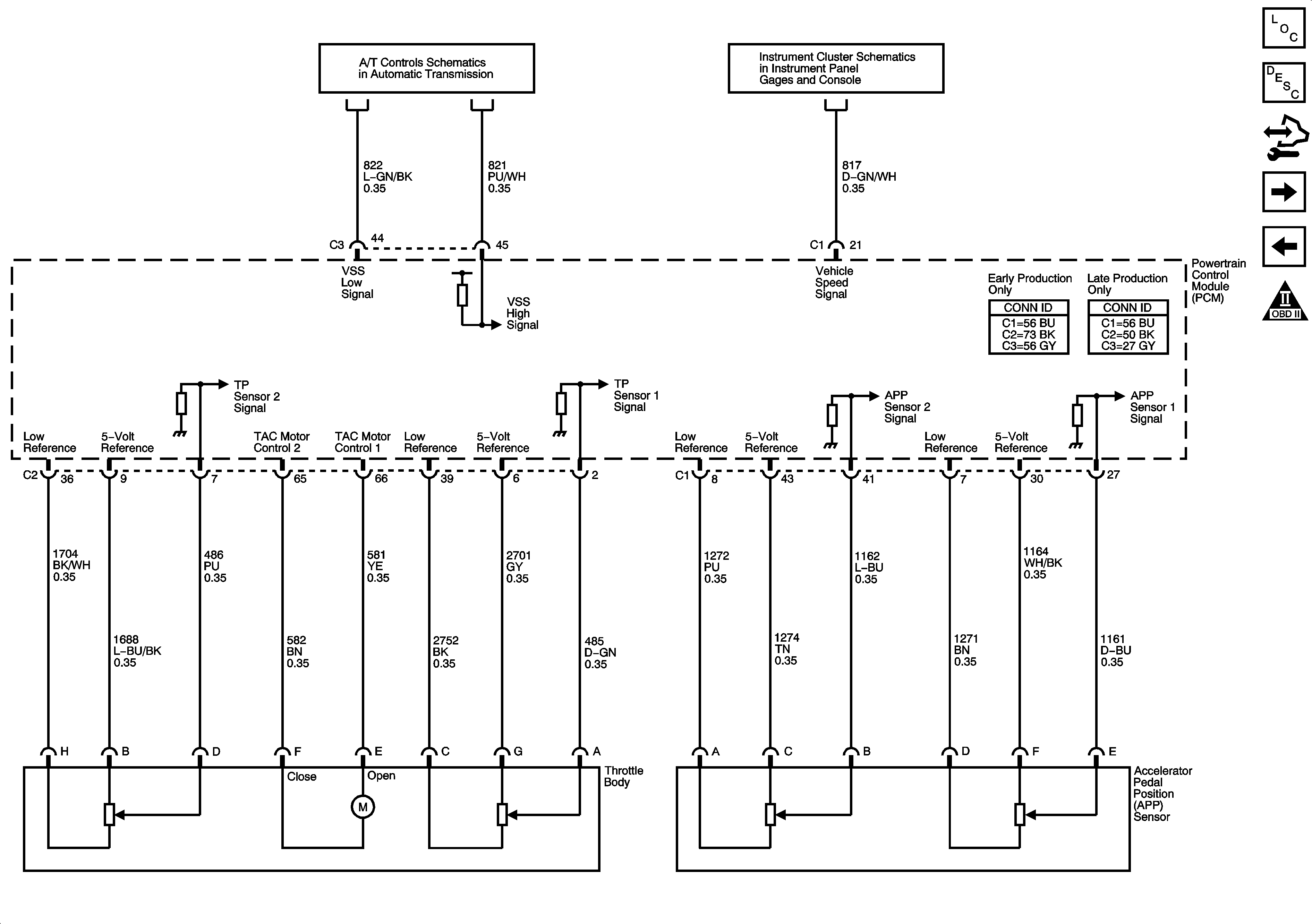
Figure 7:

Engine Data Sensors - Throttle Actuator Controls and VSS


Object Number: 1614346  Size: FS
Master Electrical Component List
Throttle Actuator Control (TAC) System Description
Control Module References
Ignition Controls - Ignition System
Engine Data Sensors - Oxygen Sensors
Engine Controls Schematic Icons
Pressure Controls, Temperature, and VSS
Gages
Figure 8:

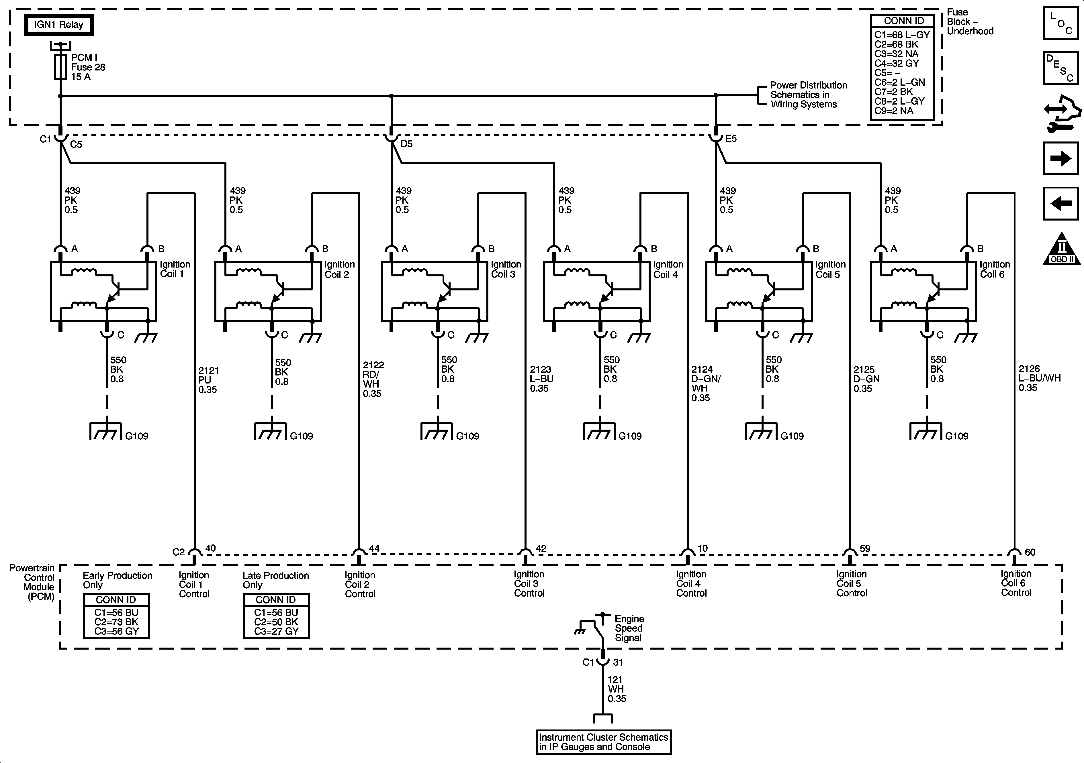
Ignition Controls - Ignition System


Object Number: 1614348  Size: FS
Master Electrical Component List
Electronic Ignition (EI) System Description
Control Module References
Ignition Controls - Sensors
Engine Data Sensors - Throttle Actuator Controls and VSS
Engine Controls Schematic Icons
Fuse Block Underhood - IGN 1 Relay
Oil Pump Assembly Figure
G109
G109
G109
G109
G109
G109
Gages
Figure 9:

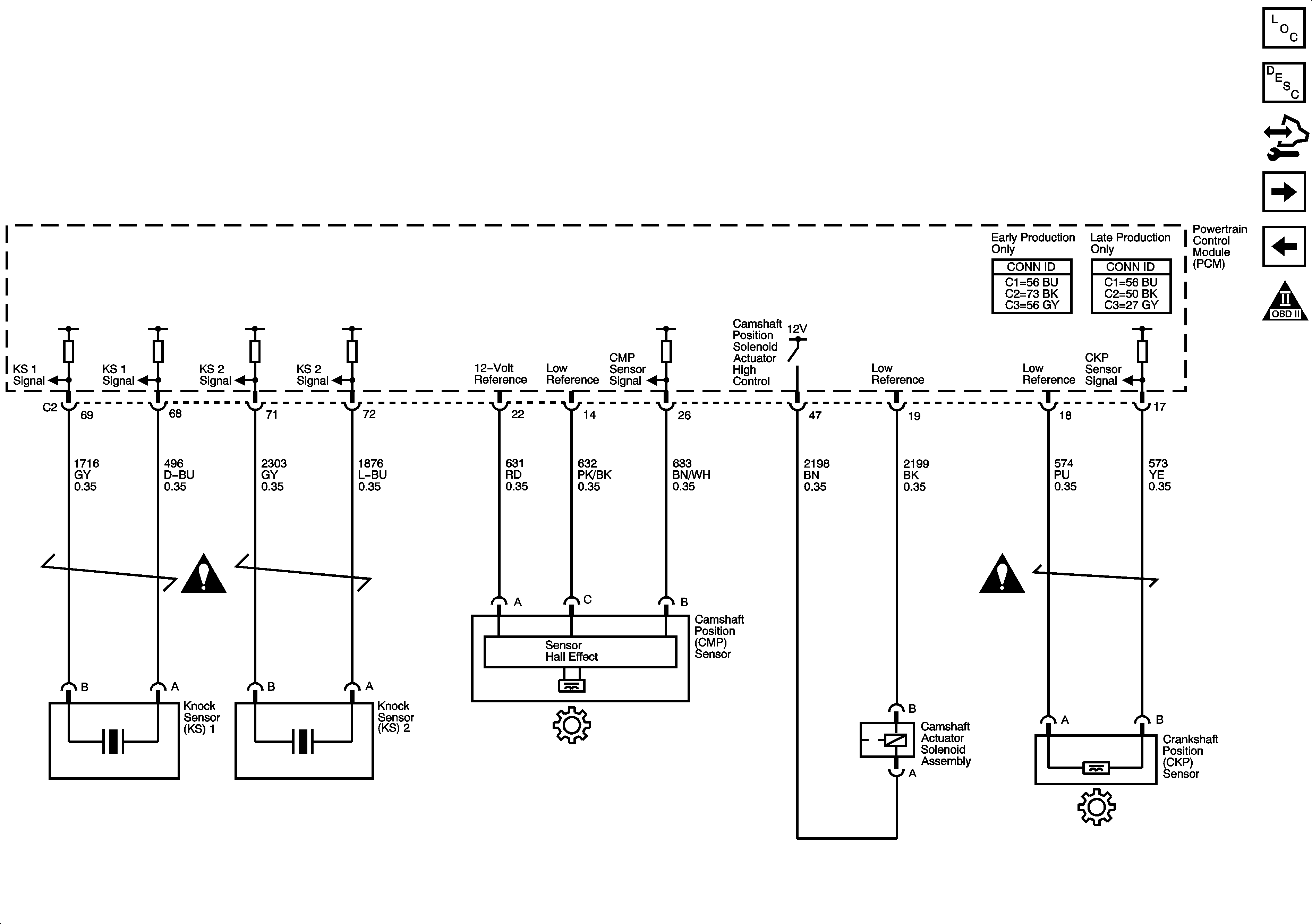
Ignition Controls - Sensors


Object Number: 1614359  Size: FS
Master Electrical Component List
Knock Sensor (KS) System Description
Control Module References
Fuel Controls - Fuel Pump Controls and Fuel Injectors
Ignition Controls - Ignition System
Engine Controls Schematic Icons
Figure 10:

Fuel Controls - Fuel Pump Controls and Fuel Indicators
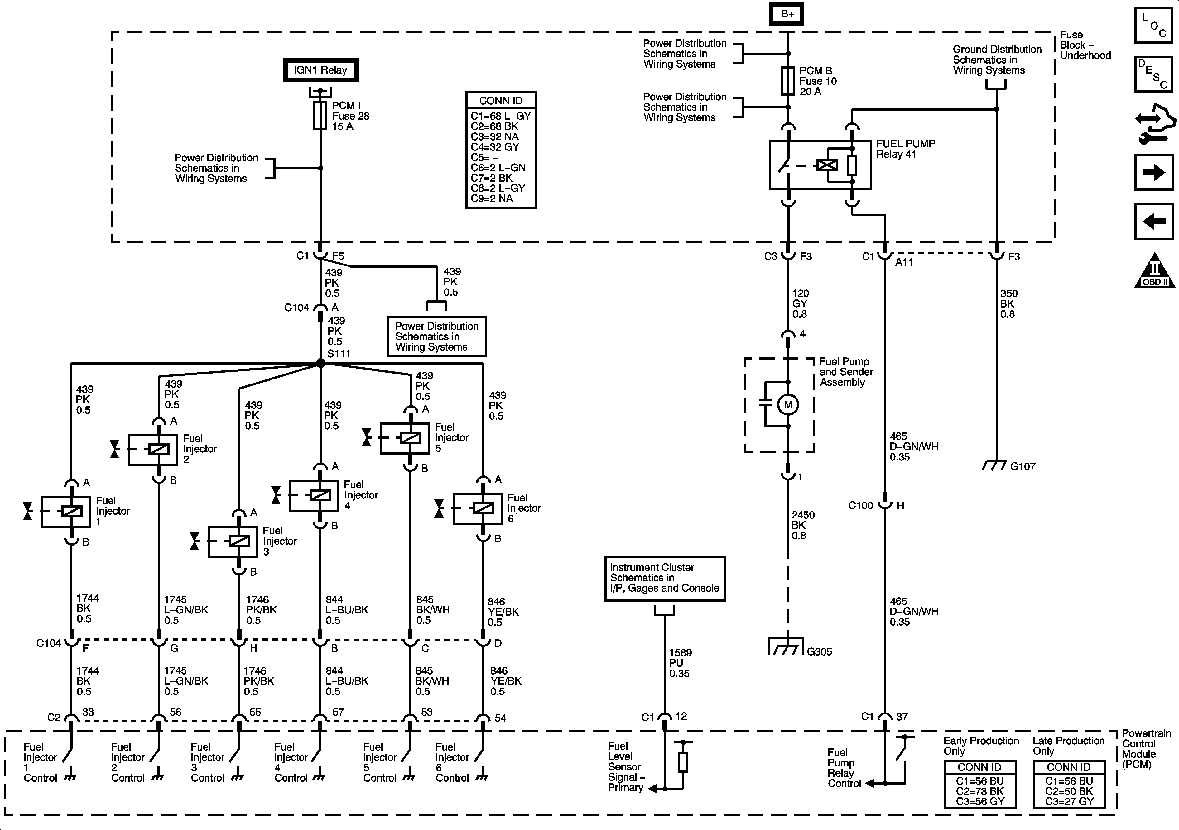

Object Number: 1614362  Size: FS
Master Electrical Component List
Fuel System Description
Control Module References
Fuel Controls - EVAP Controls
Ignition Controls - Sensors
Engine Controls Schematic Icons
AIR SOL and PCM I Fuses
Fuse Block Underhood - IGN 1 Relay
B+ Bus - Underhood Fuse Block - 2 of 2
EAP, ECM, PCMB, TBC I, and TCM CNSTR Fuses
G104, G105 and G107
Radio to Amplifier - U88
G201 - 2 of 2 and G305
Figure 11:

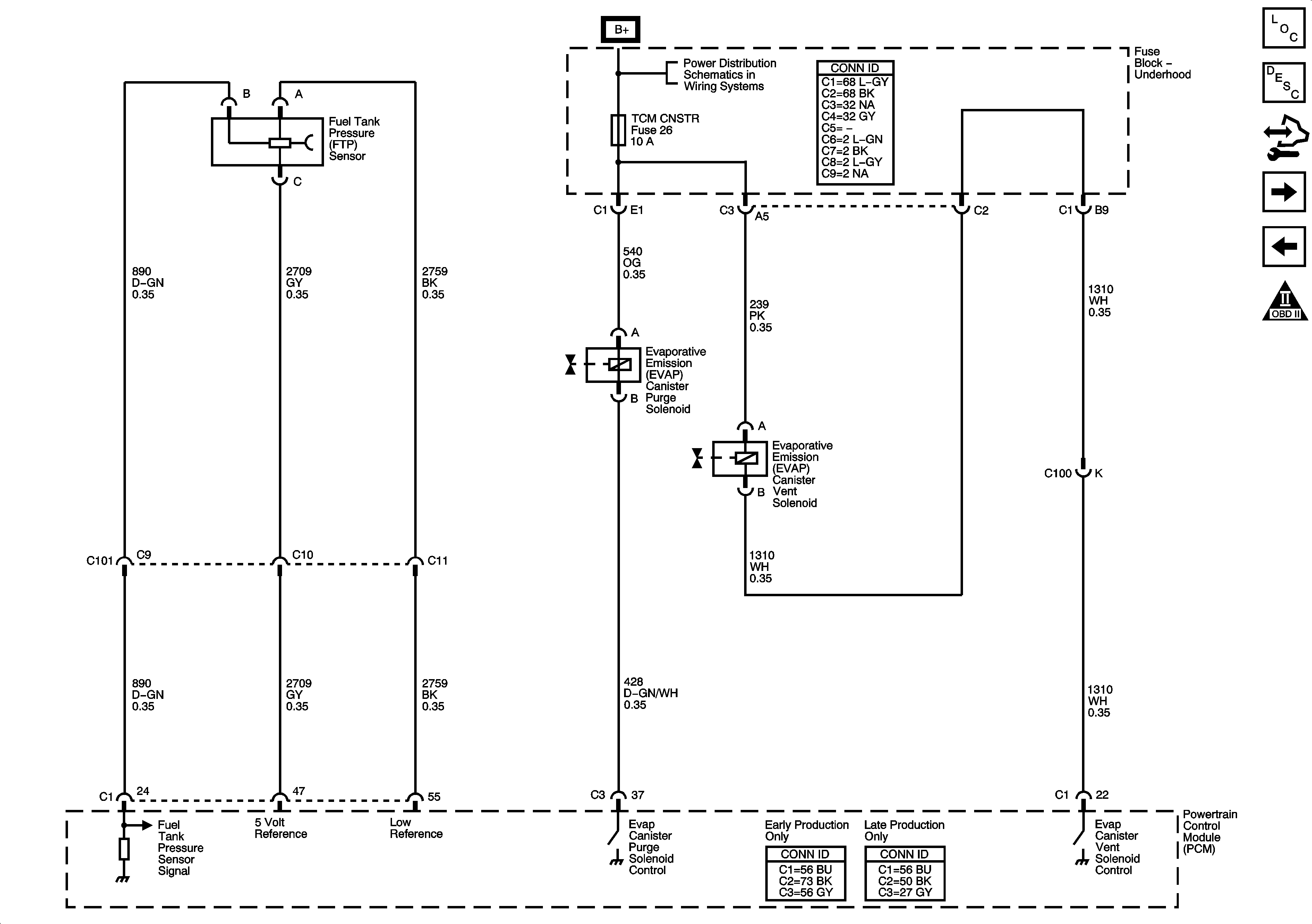
Fuel Controls - EVAP Controls


Object Number: 1614365  Size: FS
Master Electrical Component List
Evaporative Emission Control System Description
Control Module References
Controlled/Monitored Subsystem References
Fuel Controls - Fuel Pump Controls and Fuel Injectors
Engine Controls Schematic Icons
EAP, ECM, PCMB, TBC I, and TCM CNSTR Fuses
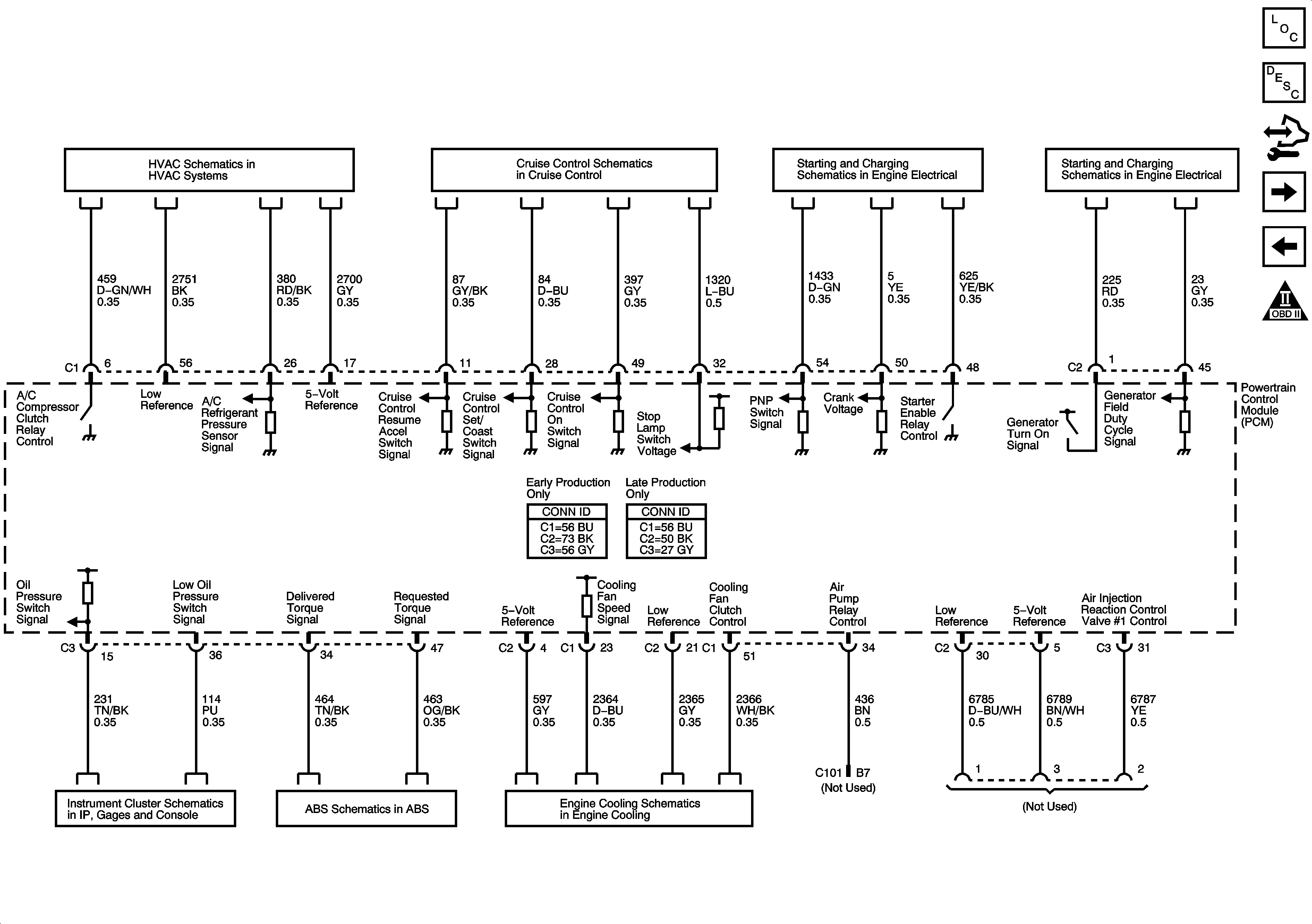
Figure 12:

Controlled/Monitored Subsystem References


Object Number: 1614370  Size: FS
Master Electrical Component List
Powertrain Control Module Description
Control Module References
Transmission Control References - A/T
Fuel Controls - EVAP Controls
Engine Controls Schematic Icons
Compressor Controls
Cruise Control - 4.2L
Starting System
Charging System
Gages
EBCM, Power, Ground, Serial Data, Indicator, and Signal Circuits
Engine Cooling Schematics
Figure 13:

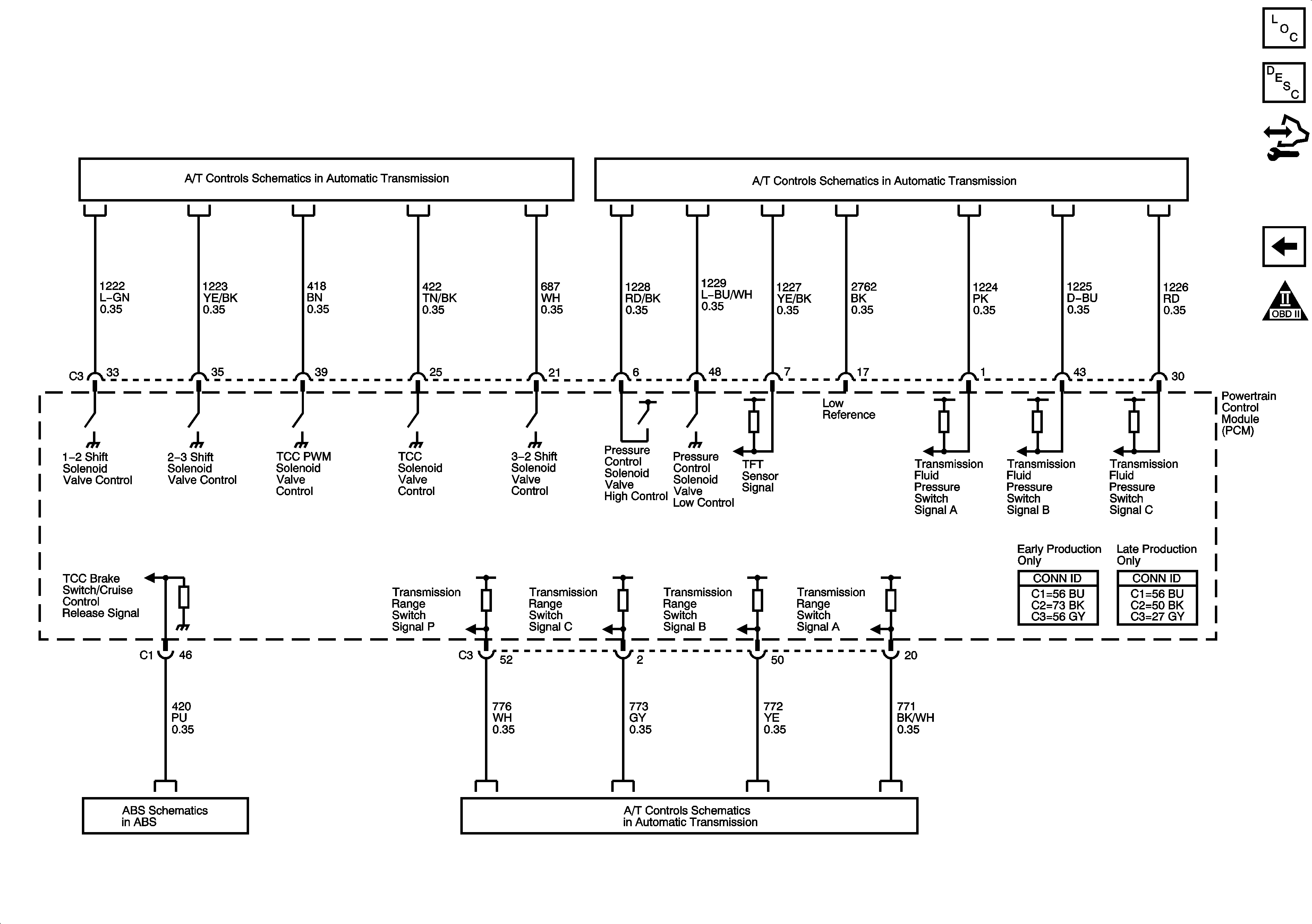
Transmission Control References - A/T


Object Number: 1614371  Size: FS
Master Electrical Component List
Powertrain Control Module Description
Control Module References
Controlled/Monitored Subsystem References
Engine Controls Schematic Icons
Shift Control and Stop Lamp Switch
Pressure Controls, Temperature, and VSS
EBCM, Power, Ground, Serial Data, Indicator, and Signal Circuits
Pressure Controls, Temperature, and VSS