For 1990-2009 cars only
Removal Procedure
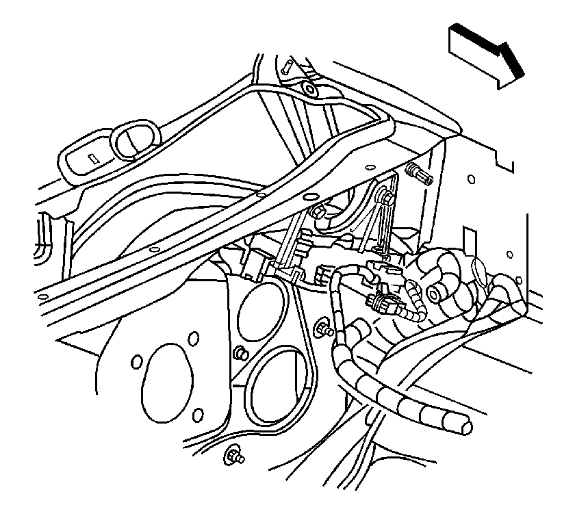
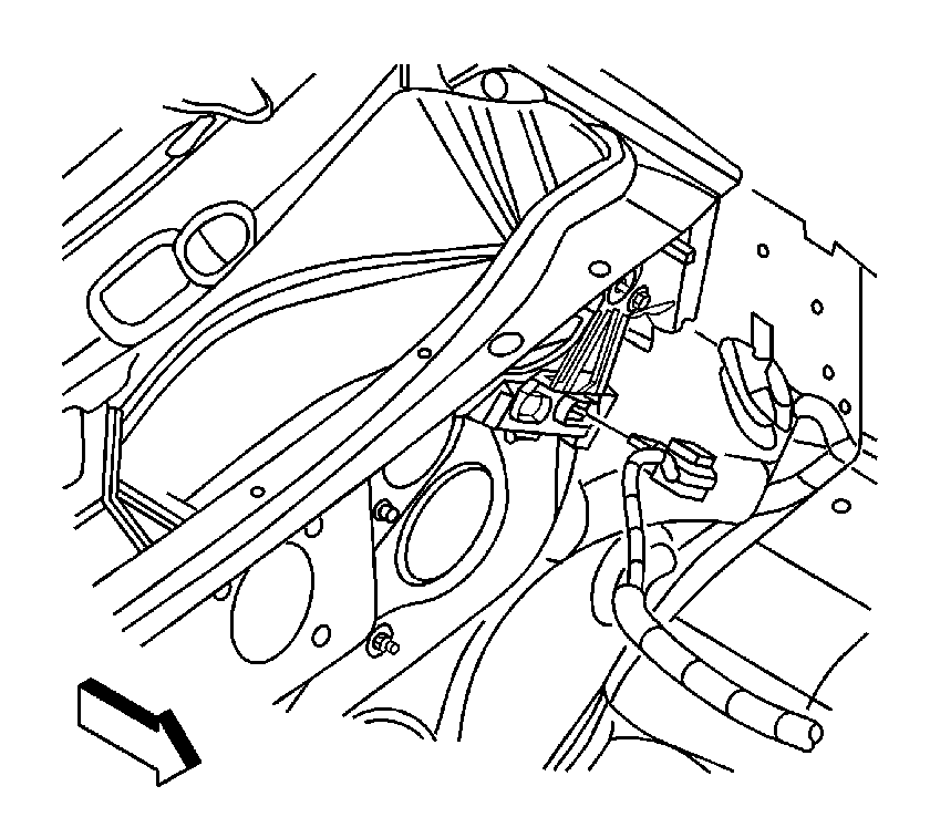
- Remove the bulk connector from the bracket, insert a small flat-bladed tool to disengage the clip.
- Disconnect the instrument panel (I/P) harness electrical connector.
- Disconnect the engine harness electrical connector.
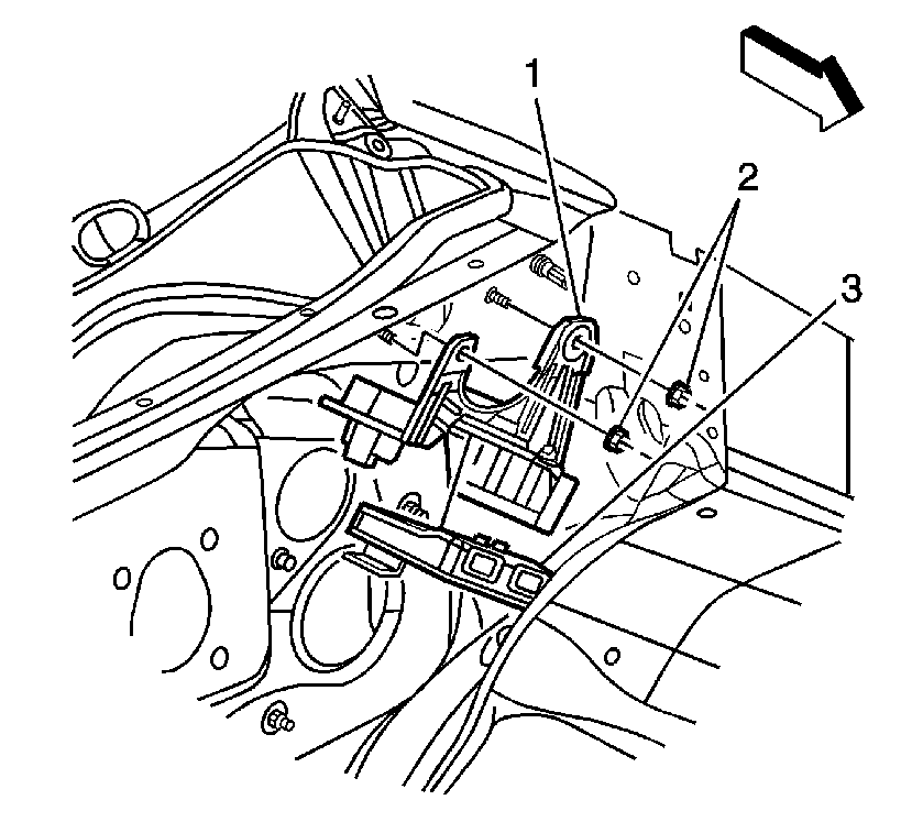
- Release the retaining tab on the side of the throttle actuator control (TAC) module (3).
- Remove the TAC module (3) from the retaining bracket (1).
- If necessary, remove the TAC module bracket nuts (2) and bracket (1).
Notice: Refer to Handling Electrostatic Discharge Sensitive Parts Notice in the Preface section.


Installation Procedure
- If necessary, install the TAC module bracket (1) and nuts (2).
- Install the TAC module (3) to the retaining bracket (1).
- Snap the TAC module (3) into retaining tab.
- Connect the engine harness electrical connector.
- Connect the I/P harness electrical connector.
- Install the bulk connector to the bracket.
- Refer to Control Module References for programming and setup information.
Notice: Refer to Handling Electrostatic Discharge Sensitive Parts Notice in the Preface section.
Notice: Refer to Fastener Notice in the Preface section.

Tighten
Tighten the nuts to 9 N·m (80 lb in).


