Tools Required
J 44551 Suction Screen Kit
Part # | Screen Size | Fitting ID Application Range |
|---|---|---|
J-44551-40 | 0.395" (10.03 mm) | 0.384-0.392" (9.75-9.96 mm) |
J-44551-60 | 0.471" (11.96 mm) | 0.460-0.468" (11.68-11.89 mm) |
J-44551-70 | 0.492" (12.50 mm) | 0.481-0.489" (12.22-12.42 mm) |
J-44551-80 | 0.500" (12.70 mm) | 0.489-0.497" (12.42-12.62 mm) |
J-44551-10 | 0.510" (12.95 mm) | 0.499-0.507" (12.67-12.88 mm) |
J-44551-20 | 0.552" (14.02 mm) | 0.541-0.549" (13.74-13.94 mm) |
J-44551-30 | 0.595" (15.11 mm) | 0.584-0.592" (14.83-15.04 mm) |
J-44551-90 | 0.600" (15.24 mm) | 0.589-0.597" (14.96-15.16 mm) |
- Using a caliper that reads to 3 decimal places, measure the ID of the suction hose or manifold suction fitting. Refer to the suction screen coverage chart above to determine the correct size screen for the application.
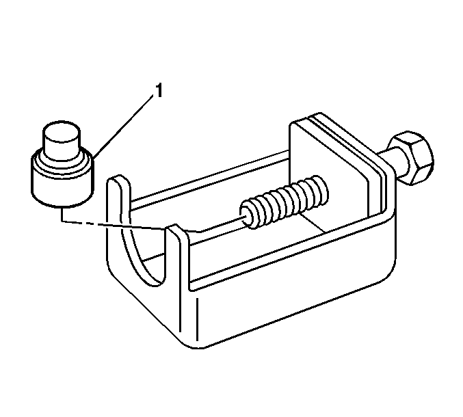
- Select and install the correct mandrel (1) on the threaded portion of the installation tool bolt.
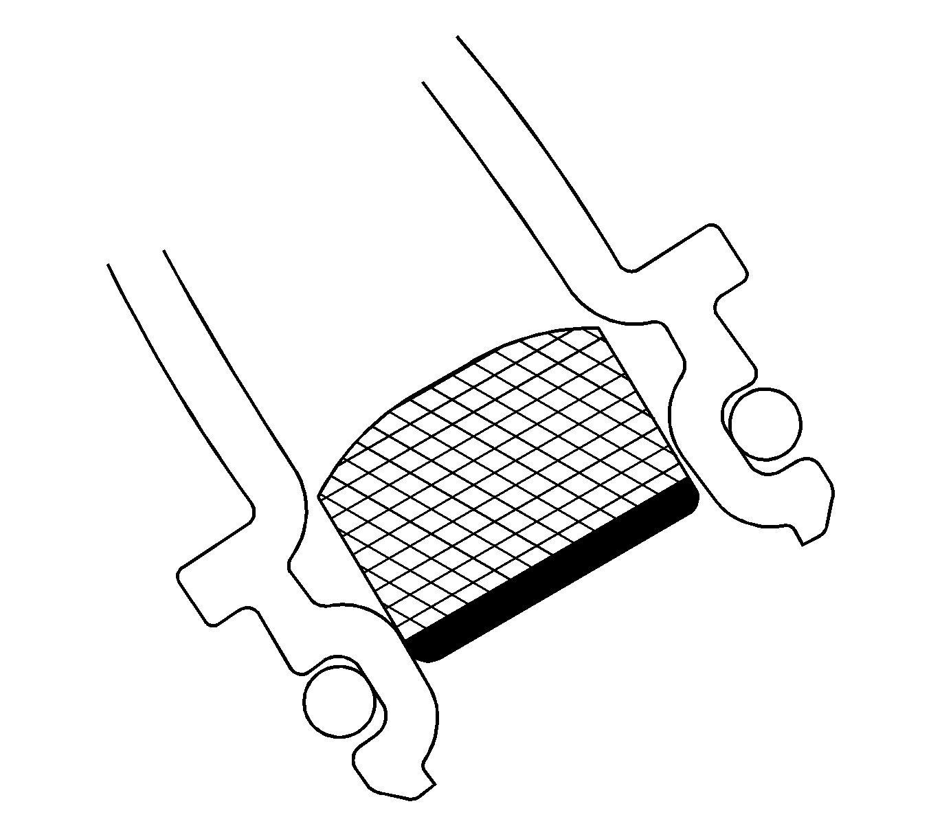
- Install the 0.471 in (11.96 mm) screen in the middle of the reduced diameter point of the fitting.
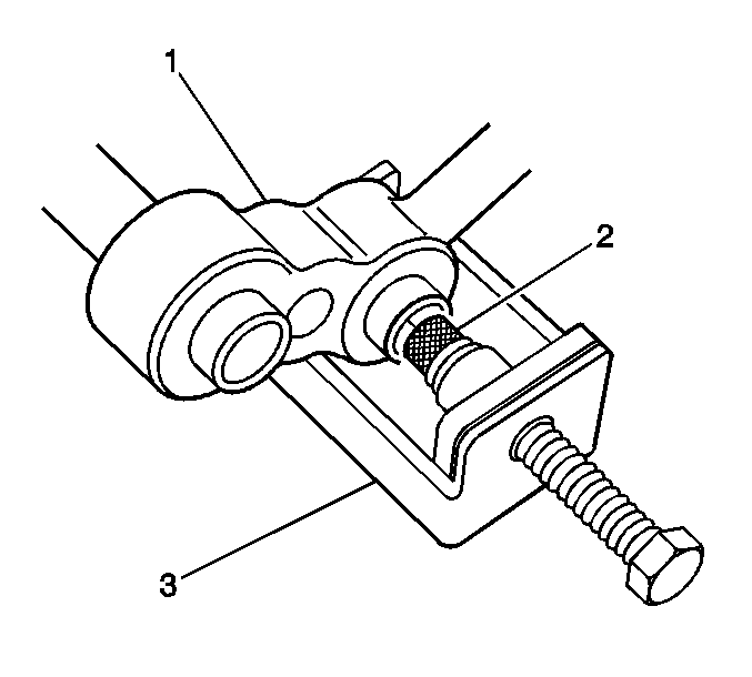
- Place the suction hose fitting or suction hose side of the manifold into the installation tool fixture J-44551-5 (3) so it is supported by the tools legs.
- Lubricate the A/C suction screen with the applicable refrigerant oil.
- Align the screen (2), basket first, into the suction hose bore then hand tighten the bolt until contact is made between the hose, screen and tool.
- Turn the bolt of the installation tool clockwise pressing the screen into the bore until the mandrel shoulder contacts the end of the hose fitting.
- Unscrew the bolt and remove the installation tool from the hose or manifold.
- Install the J-44551-1 Suction Screen Notification Label.
Important: Suction screens are intended to be installed in the suction hose after a major compressor failure.

| • | The brass Universal Mandrel is for use on hose fittings with a smooth bore where the screen installs flush with the end of the fitting. |
| • | The 0.471 in (11.96 mm) Mandrel is only for the 0.471 in (11.96 mm) screen in hose fittings with an internal hourglass shape where the screen installs at the recessed, reduced diameter point. |


Important: Correct placement of the J-44551-5 is critical.
Important: Clean the surface to be used for attaching the label.
