Tools Required
| • | DT-47752 Split Plate Set |
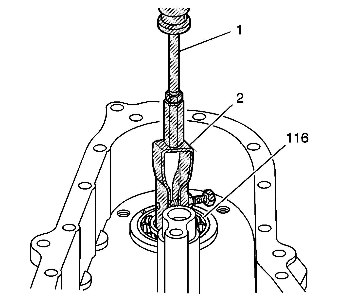
| • | J-2619-A Slide Hammer w/Adapter |
| • | J 8107-2 Side Bearing Puller Pilot |
| • | J 8433 Two Jaw Puller |
| • | J 22888-20A Universal Two Jaw Puller |
| • | J 23444-A Extreme Press Lubricant - 1/4-Ounce Tube |
| • | J 29369-1 Bushing and Bearing Remover |
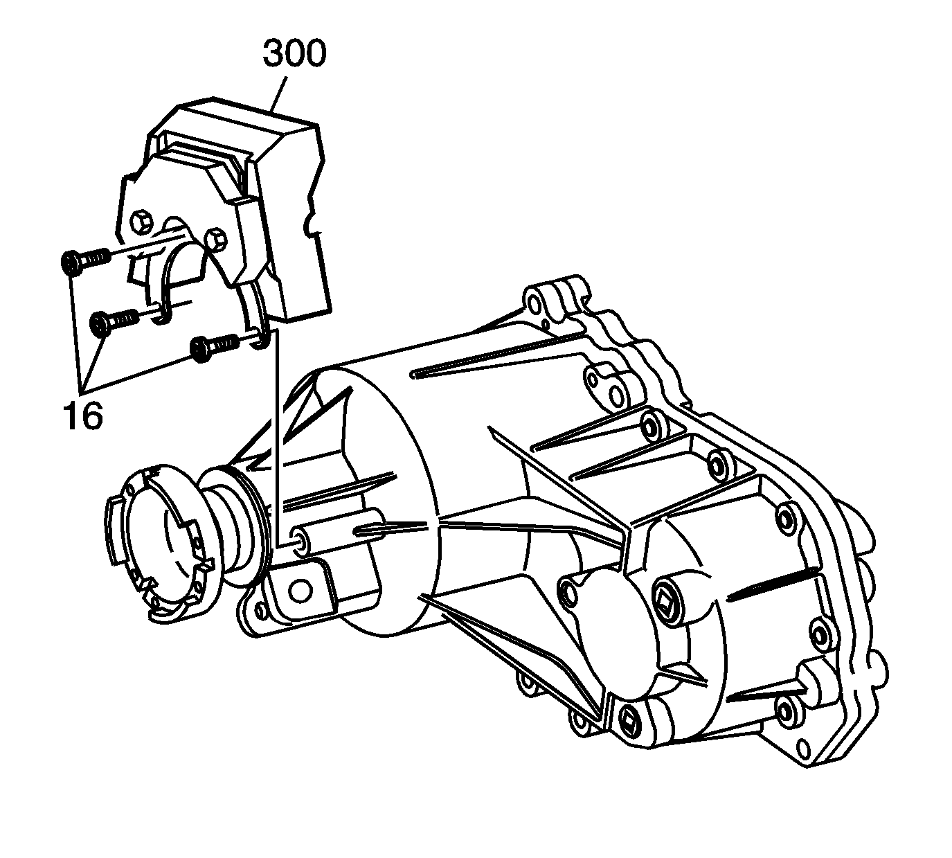
- Remove the bolts (16) and the dampener (300), some models.
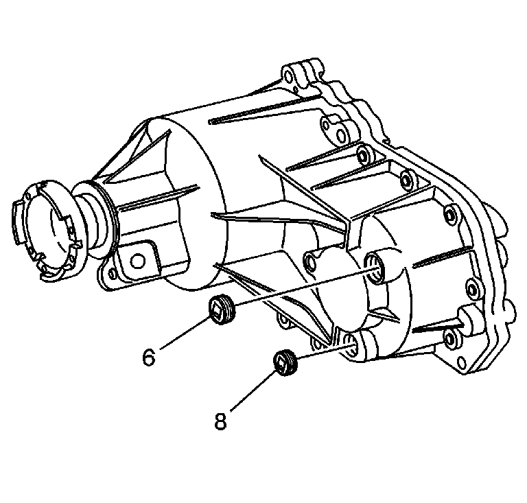
- Remove the drain plug (8) and the fill plug (6). Ensure all transfer case fluid is drained out of the transfer case.
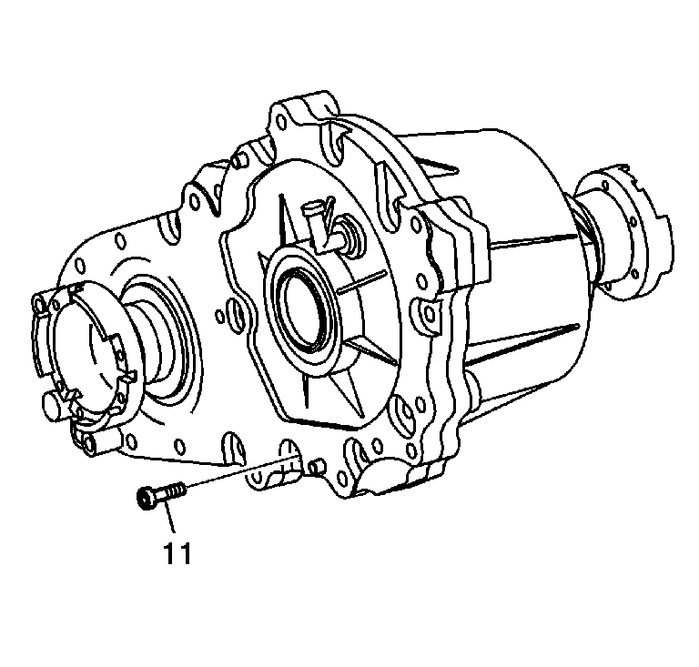
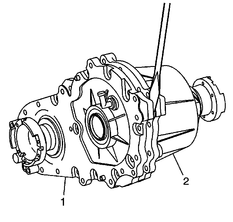
- Remove the 17 case attaching bolts (11).
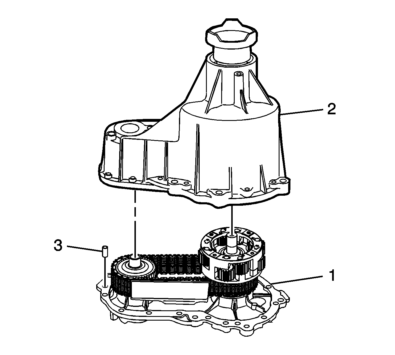
- Using a screwdriver at the pry points located on the case (1) and cover (2), pry the case (1) and cover (2) apart.
- Separate the case (1) and cover (2).
- Remove the alignment dowel (3) from the case, if necessary.
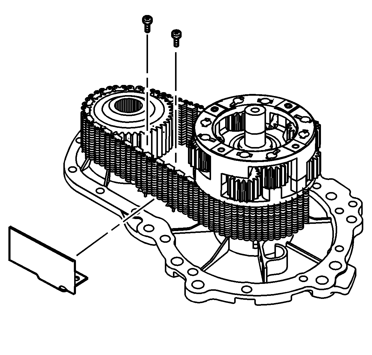
- Remove the chain snubber.
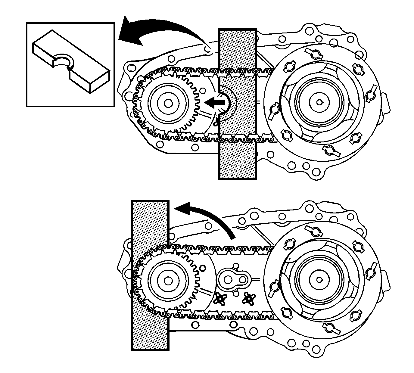
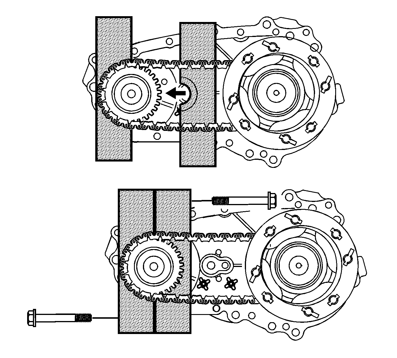
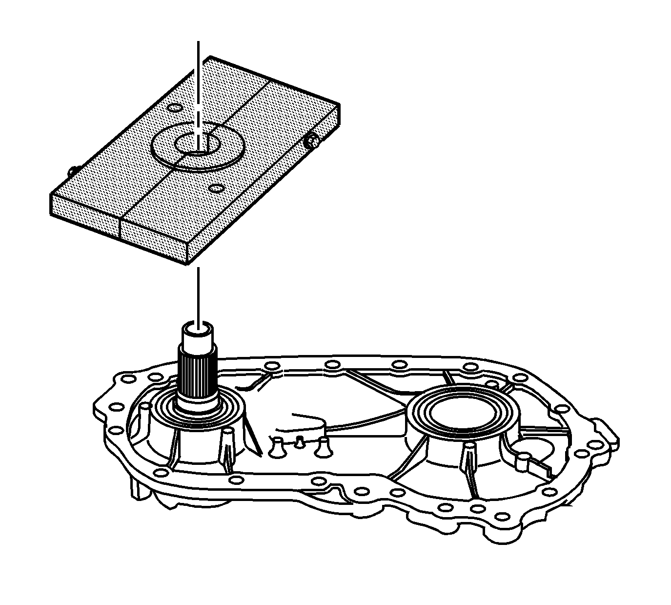
- Install 1 plate of the DT-47752 perpendicular to the chain and rotate 180 degrees.
- Install the second plate perpendicular to the chain and secure with the short plate bolts.
- Install the DT-47752-2 (2) onto the front output shaft (112).
- Using the long bolts and washers from DT-47752 , install the J 8433 (1). Tighten evenly so the puller remains parallel to the plates.
- Install DT-47752-3 into the input shaft.
- Using an impact wrench, tighten the forcing screw of the DT-47752-2 in order to remove the sprockets, chain and carrier assembly.
- Remove the J 8433 (1) and the DT-47752-2 (2).
- Remove the lower sprocket (112), chain (109) and carrier (111) as an assembly.
- Remove the DT-47752 from the case.
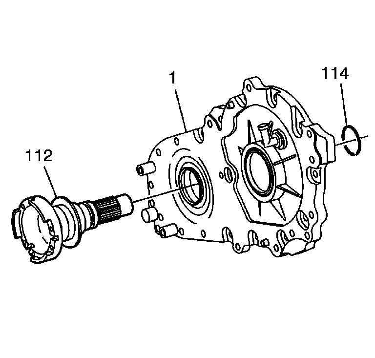
- Remove the snap ring (114).
- Push the front output shaft (112) from the case (1).
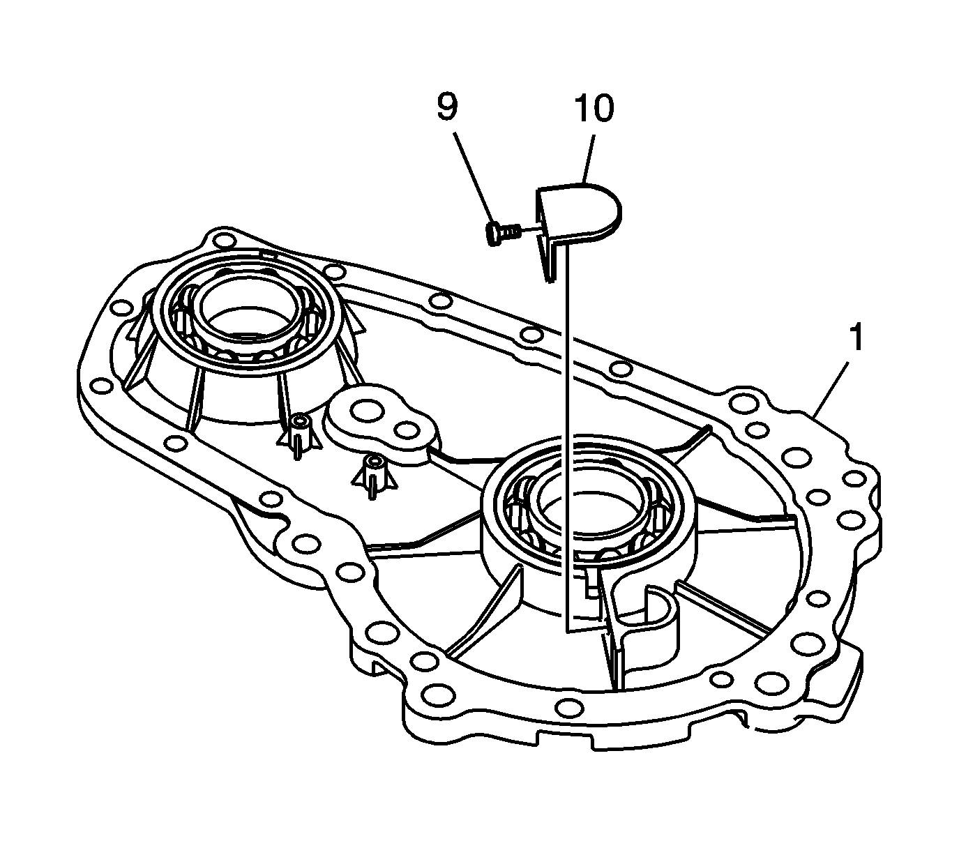
- Remove the vent baffle bolt (9) and baffle (10) from the case (1).
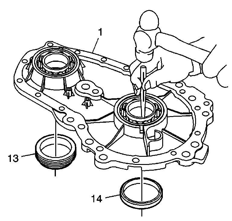
- Using a hammer and a suitable driver, remove the front output seal (13) and input seal (14) from the case (1).
- Using a hammer and a suitable punch, remove the front output bearing (113) and input bearing (117) if they are to be replaced.
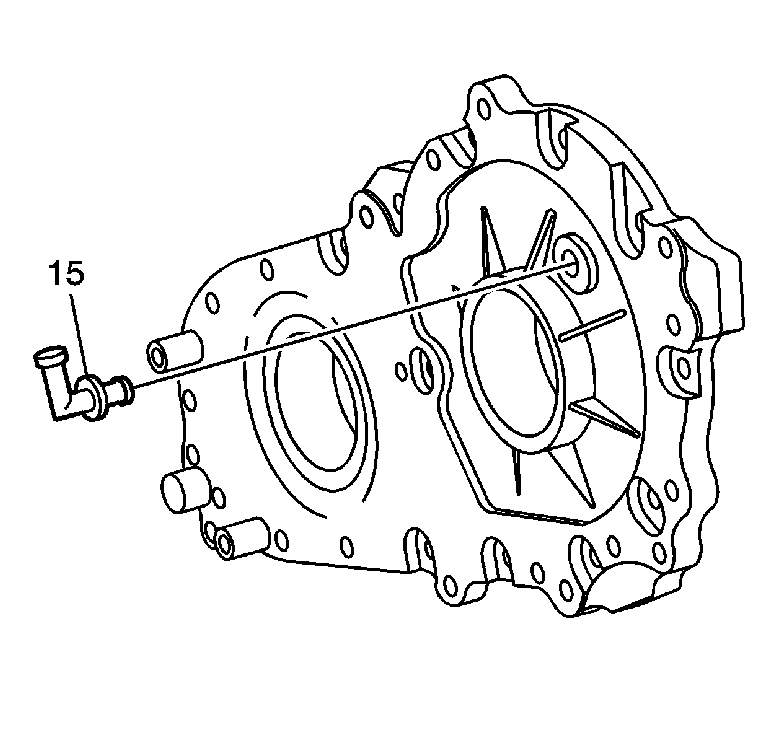
- If required, remove the vent (15) and discard.
- Replace it with a NEW vent.
- Remove the thrust washer (100) from the carrier (111).
- Using a press, remove the input shaft assembly (118, 107 and 110) from the carrier (111).
- Note the direction of the carrier assembly (111). The groove around the splines face toward the output shaft.
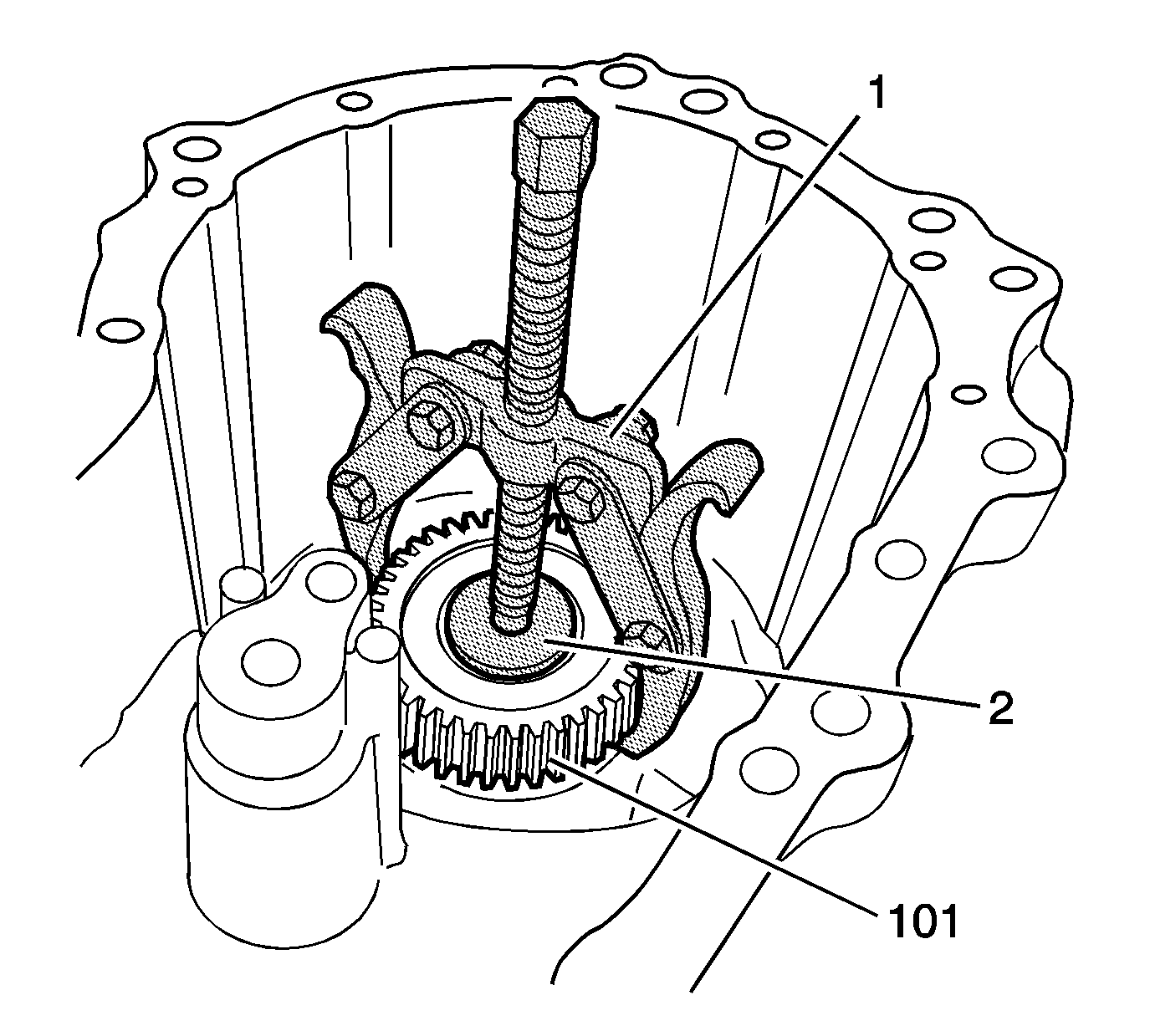
- Using the J 22888-20A (1) and the J 8107-2 (2), remove the rear sun gear (101) from the rear output shaft.
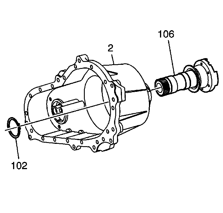
- Using snap ring pliers, remove the snap ring (102) from the output shaft (106).
- Push the output shaft (106) from the cover (2).
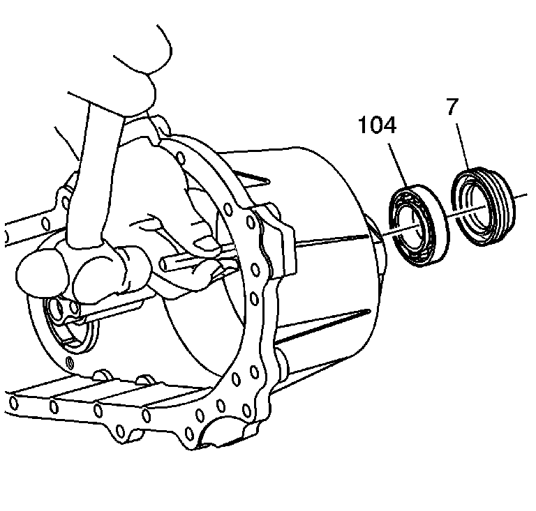
- Using a hammer and a suitable punch, from inside the cover, drive out the rear output seal (7) and the outside output bearing (104).
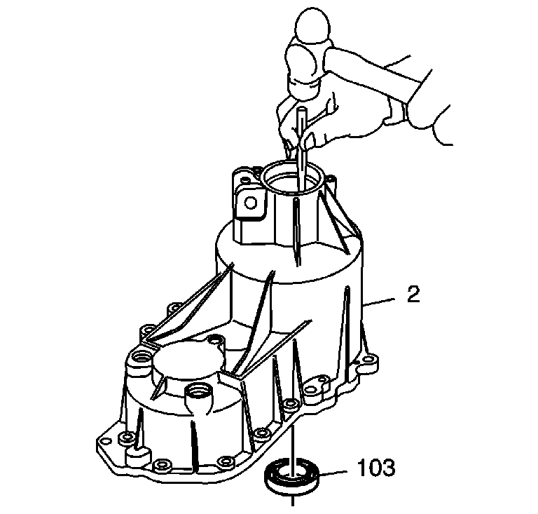
- Using a hammer and a suitable punch, from outside the cover (2), inside the output shaft bore, drive out the inner output shaft bearing (103).
- Using the J-2619-A (1) and the J 29369-1 (2), remove the front output cover bearing (116) from the cover.
Important: To prevent thread damage, clean exposed bolt threads before removing bolts.
Notice: Refer to Machined Surface Damage Notice in the Preface section.
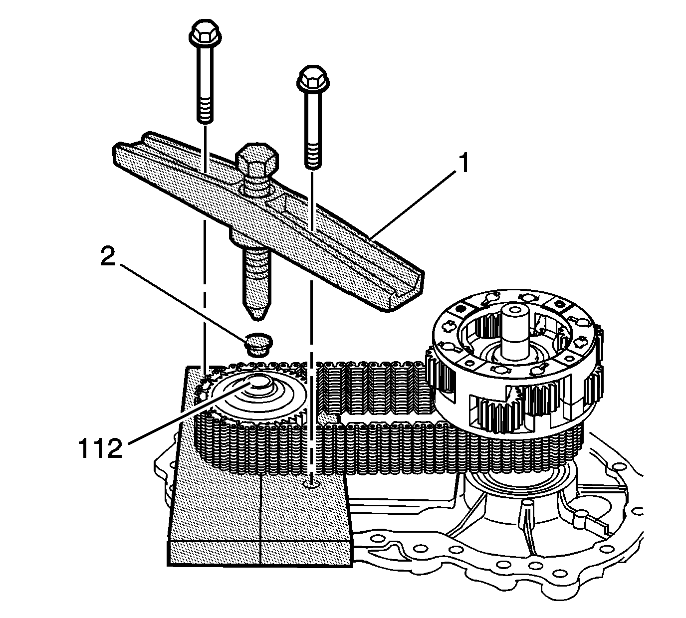
Important: Use high pressure grease J 23444-A on the screw threads.
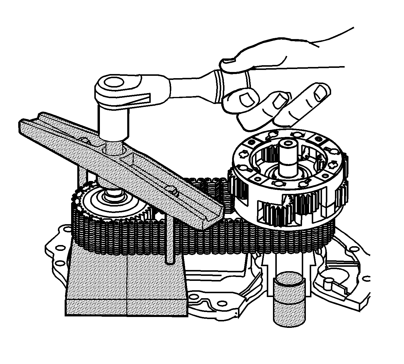
Notice: Failure to support the input shaft and carrier during removal may bind and damage the chain.

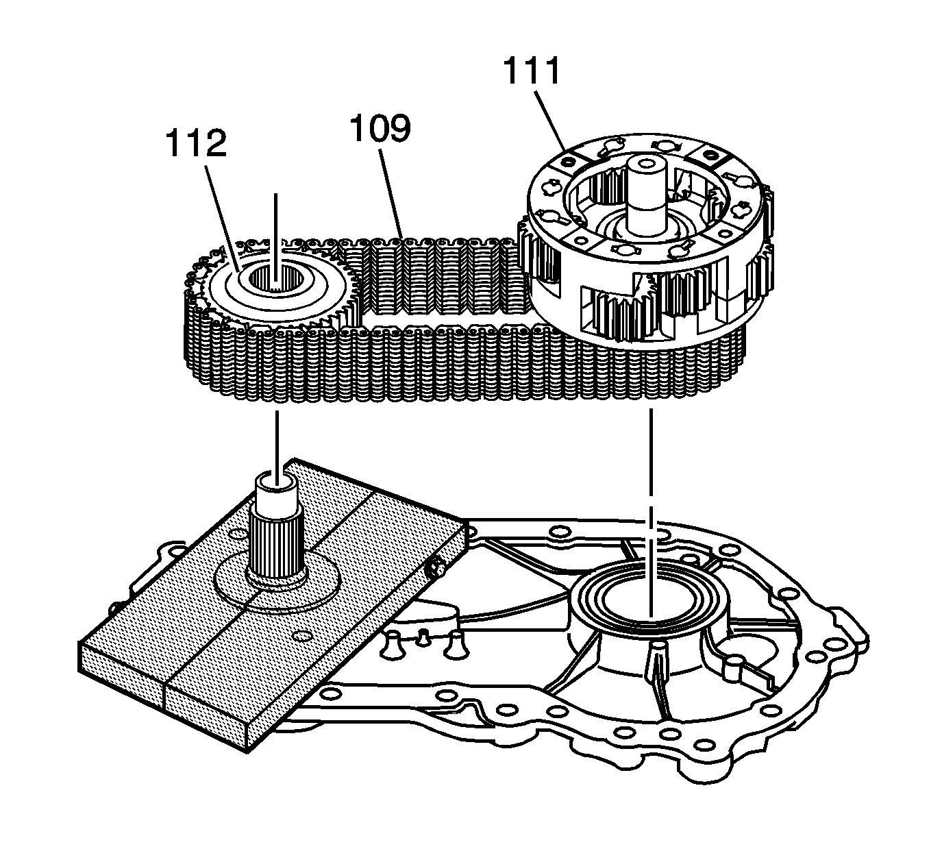
Important: If the chain and sprockets are to be used again, note the position of the blue chain link, in or out.
Notice: Refer to Transfer Case Seal Removal Notice in the Preface section.
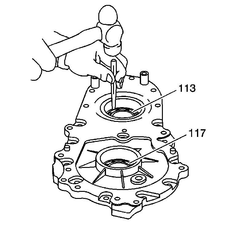
Important: Only remove the bearings if they are to be replaced.
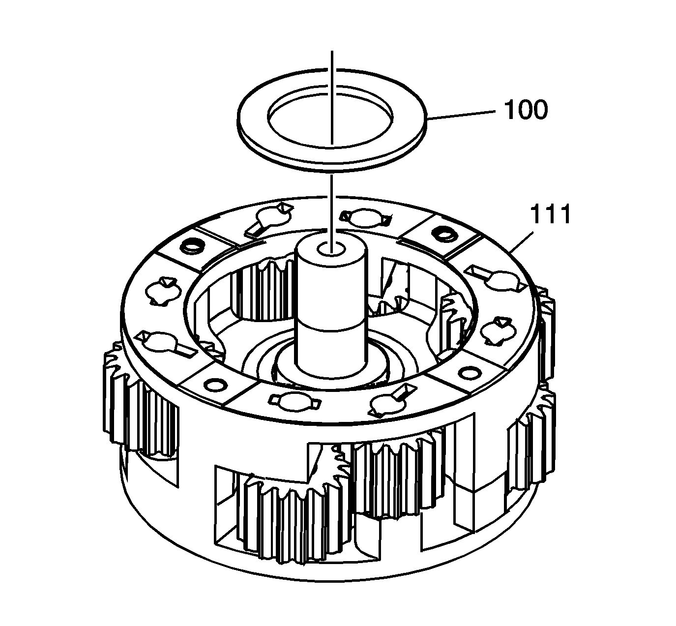
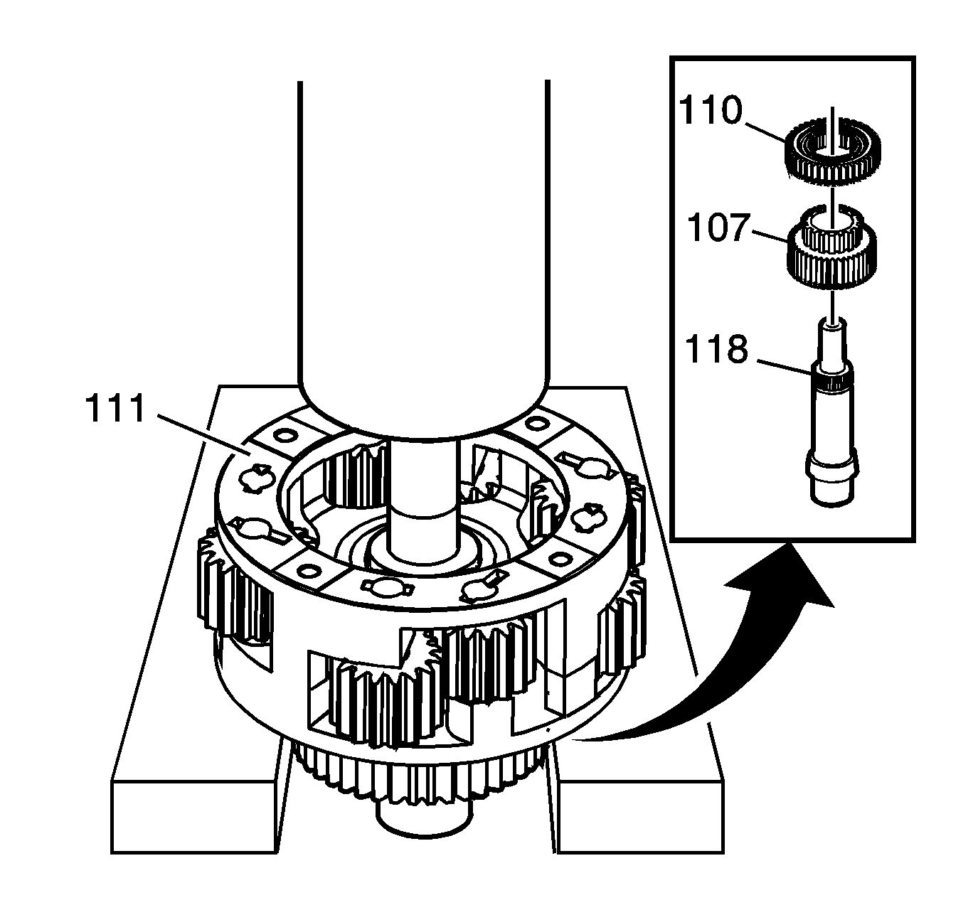
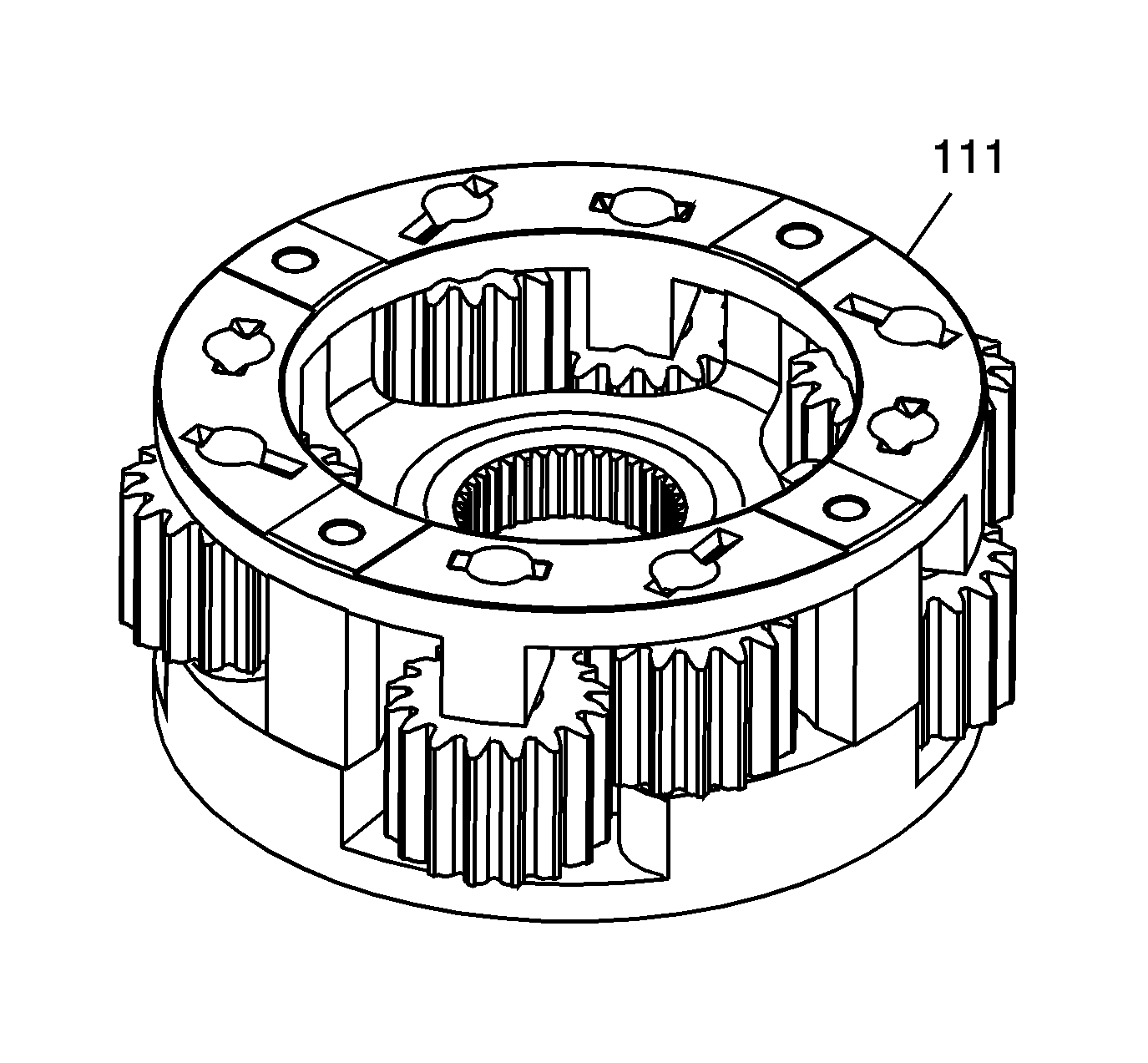
Important: The carrier assembly (111) must be installed with the thrust washer and groove around the splines toward the output shaft. Reversing this will cause a mis-build and the wrong torque split of 60/40.
Notice: Refer to Transfer Case Seal Removal Notice in the Preface section.
Notice: Refer to Transfer Case Bearing Removal Notice in the Preface section.
Notice: Refer to Transfer Case Bearing Removal Notice in the Preface section.
Notice: Refer to Transfer Case Bearing Removal Notice in the Preface section.
