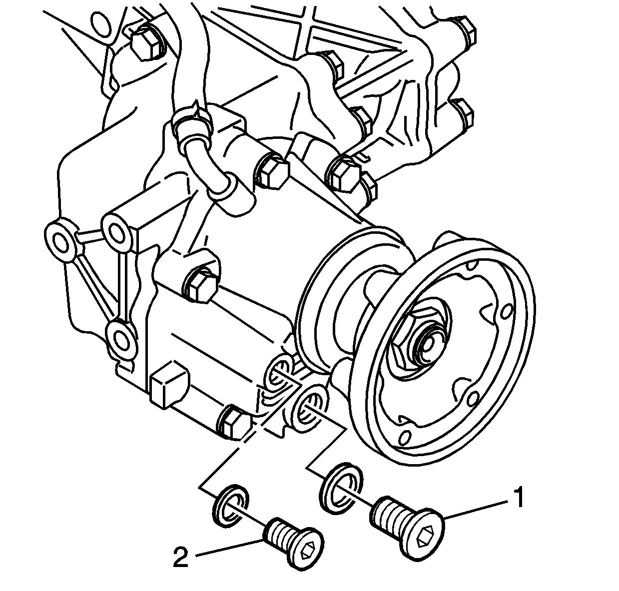
- Remove the drain plug (1) from the
extension housing. Allow the gear oil to drain.
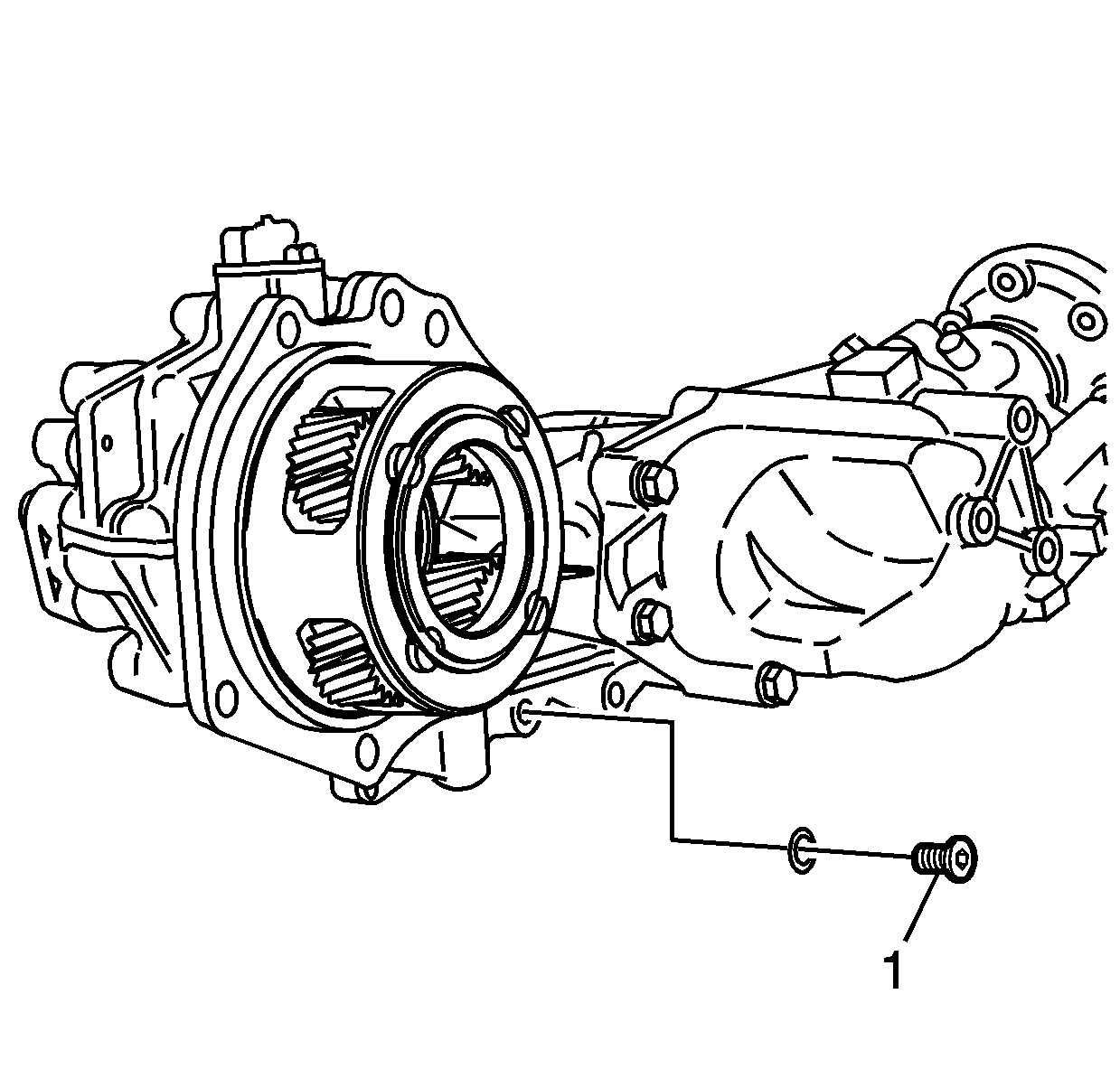
- Remove the drain plug (1) from the
left case. Allow the transmission oil to drain.
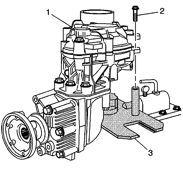
- Install the transfer case assembly (1)
onto the
J 44755
(3).
Position the carrier onto the post of the fixture.
Notice: Use the correct fastener in the correct location. Replacement fasteners
must be the correct part number for that application. Fasteners requiring
replacement or fasteners requiring the use of thread locking compound or sealant
are identified in the service procedure. Do not use paints, lubricants, or
corrosion inhibitors on fasteners or fastener joint surfaces unless specified.
These coatings affect fastener torque and joint clamping force and may damage
the fastener. Use the correct tightening sequence and specifications when
installing fasteners in order to avoid damage to parts and systems.
- Install the retaining bolts (2).
Tighten
Tighten the bolts to 50 N·m (37 lb ft).
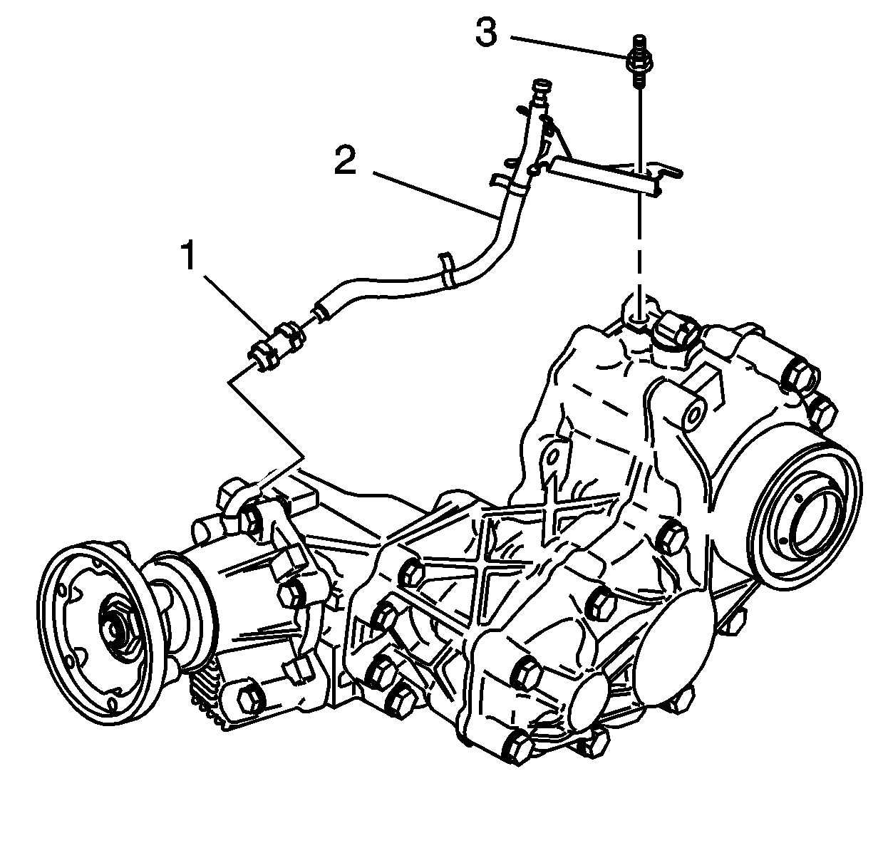
- Remove the hose and clamp assembly (1),
vent hose with bracket (2), and bolt (3).
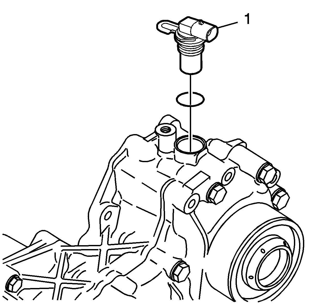
- Remove the speed sensor (1).
- Remove the O-ring seal from the sensor, if required. The O-ring
seal may be reused if not cut or damaged.
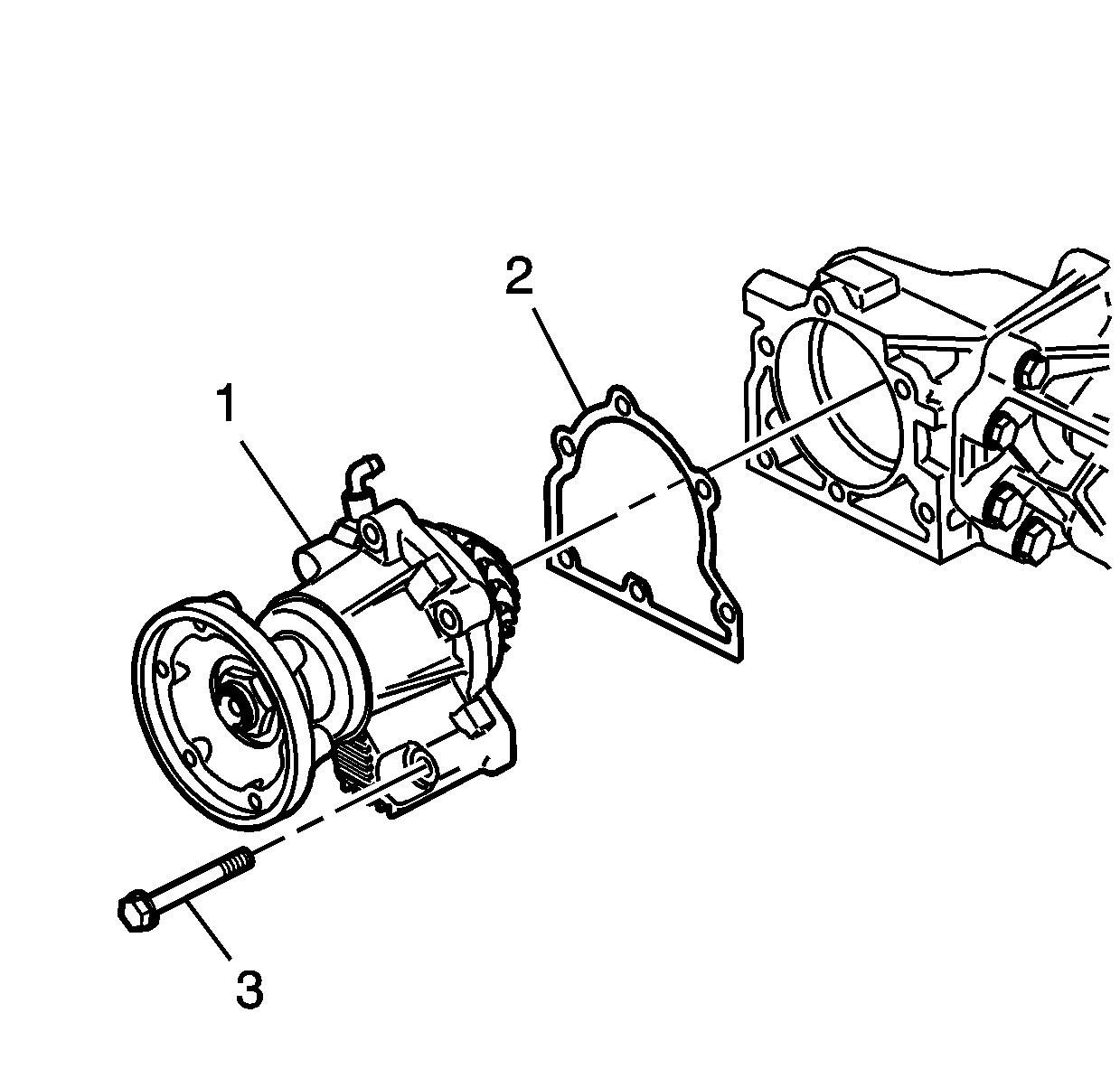
- Remove the extension housing assembly (1),
bolts (3), and shim (2). Mark or tag the shim for assembly.
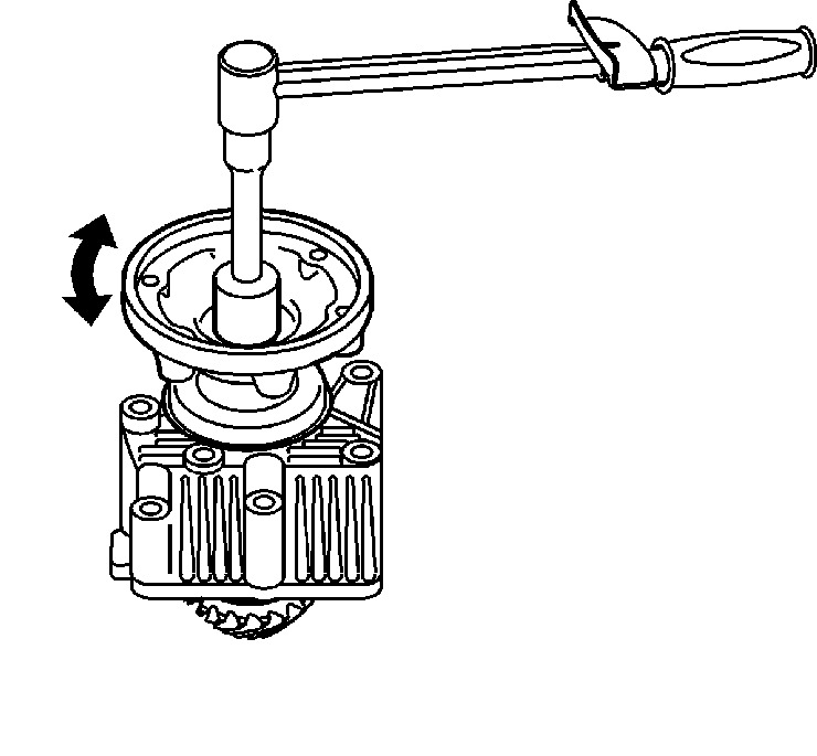
- If
reusing the drivenshaft bearings, measure in both directions, the rotating torque
of the drivenshaft and record the value for assembly.
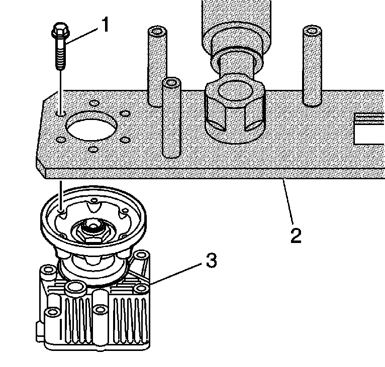
- Install the extension housing assembly (3)
and the M8 x 1.25 bolts (1) to the
J 44755
(2).
Tighten
Tighten the bolts to 25 N·m (18 lb ft).
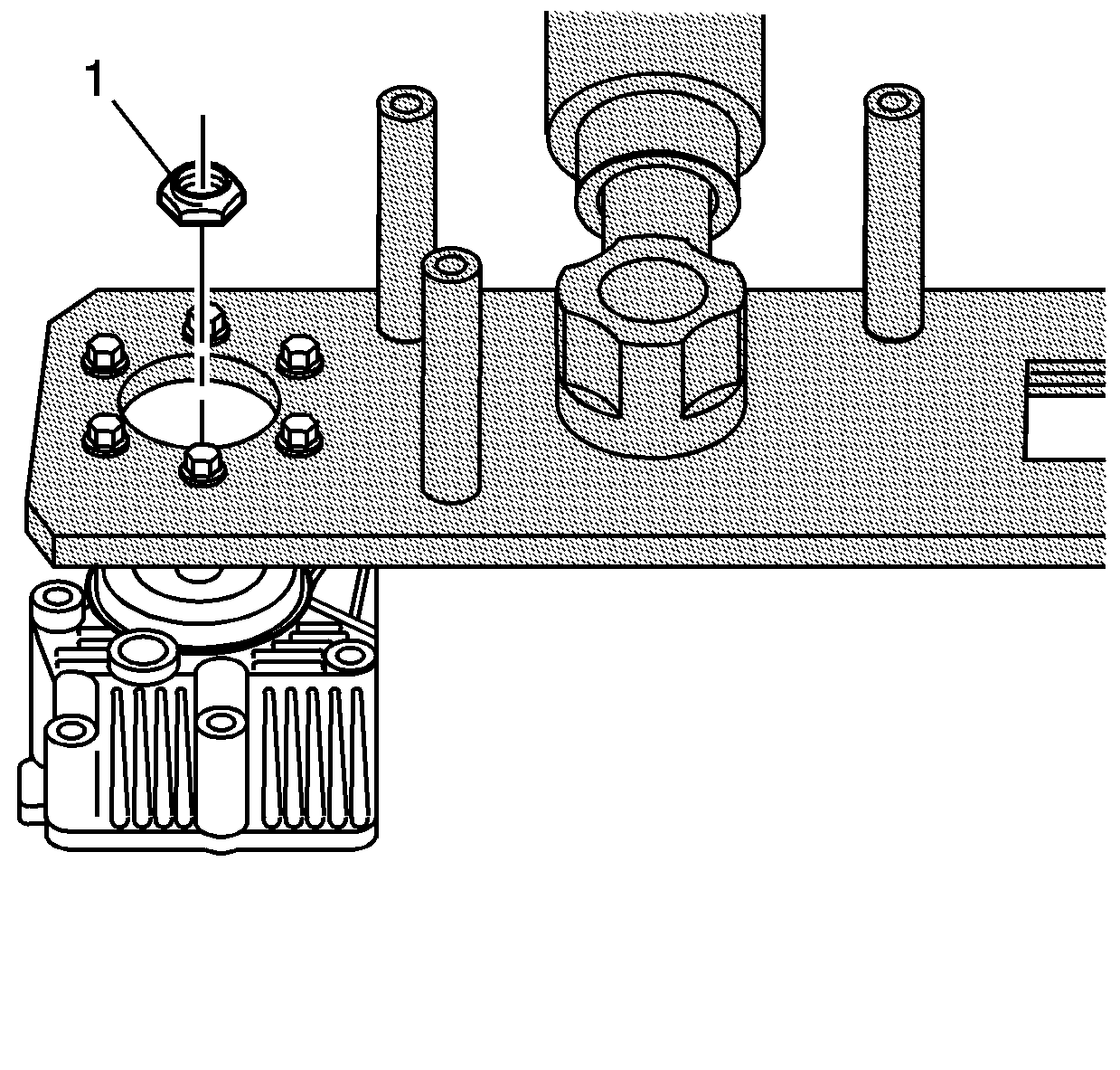
- Remove the nut (1).
- Remove the extension housing assembly and bolts from
J 44755
.
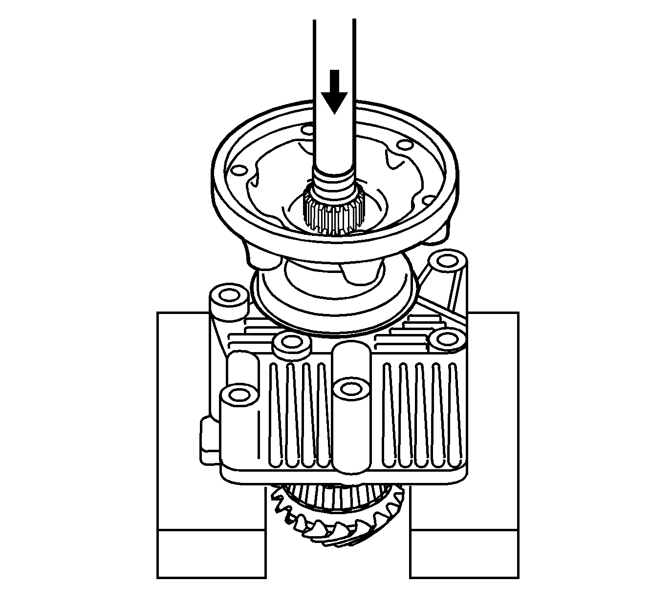
- Position the extension housing assembly
into a press.
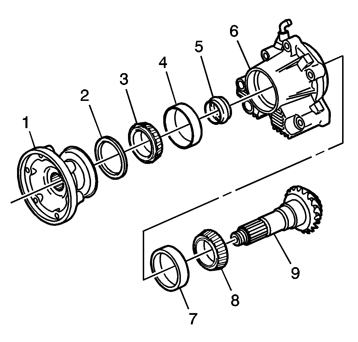
- Remove the flange (1), spacer (5),
and shaft (9) from the housing (6). Discard the spacer (5).
- Remove the oil seal (2) and bearing (3).
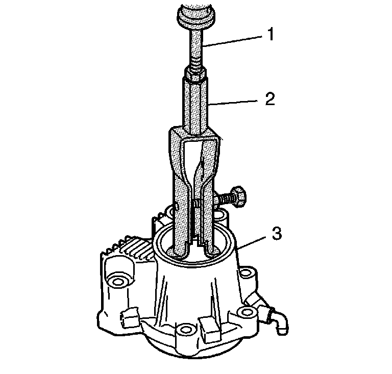
- Use
the
J 44380
(2) and the
J 2619-01
(1) in order
to remove the bearing races from the housing (3), if required.
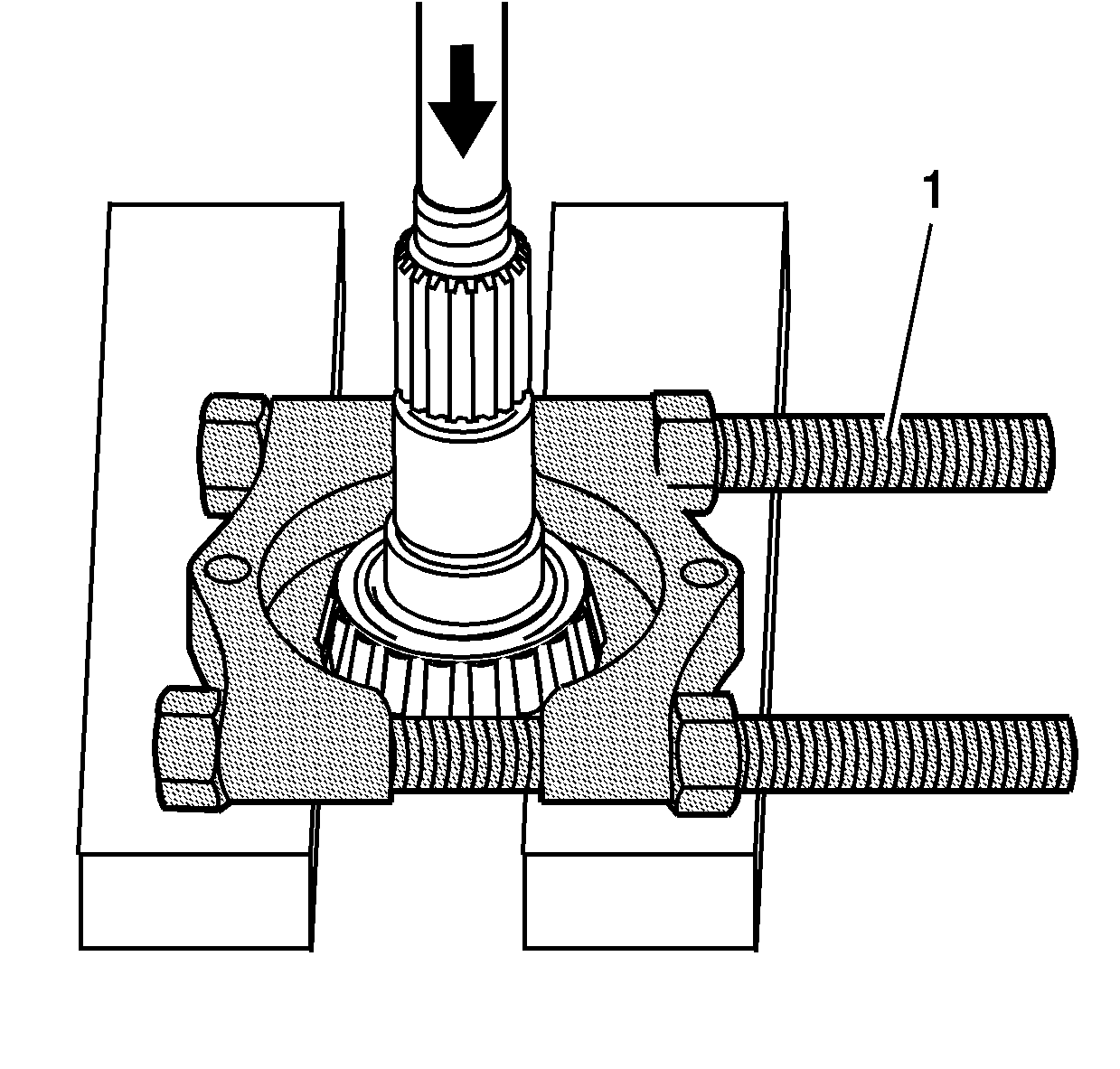
- Install
J 22912-B
(1) or equivalent onto the shaft.
- Position the shaft into a press.
- Remove the bearing from the shaft.
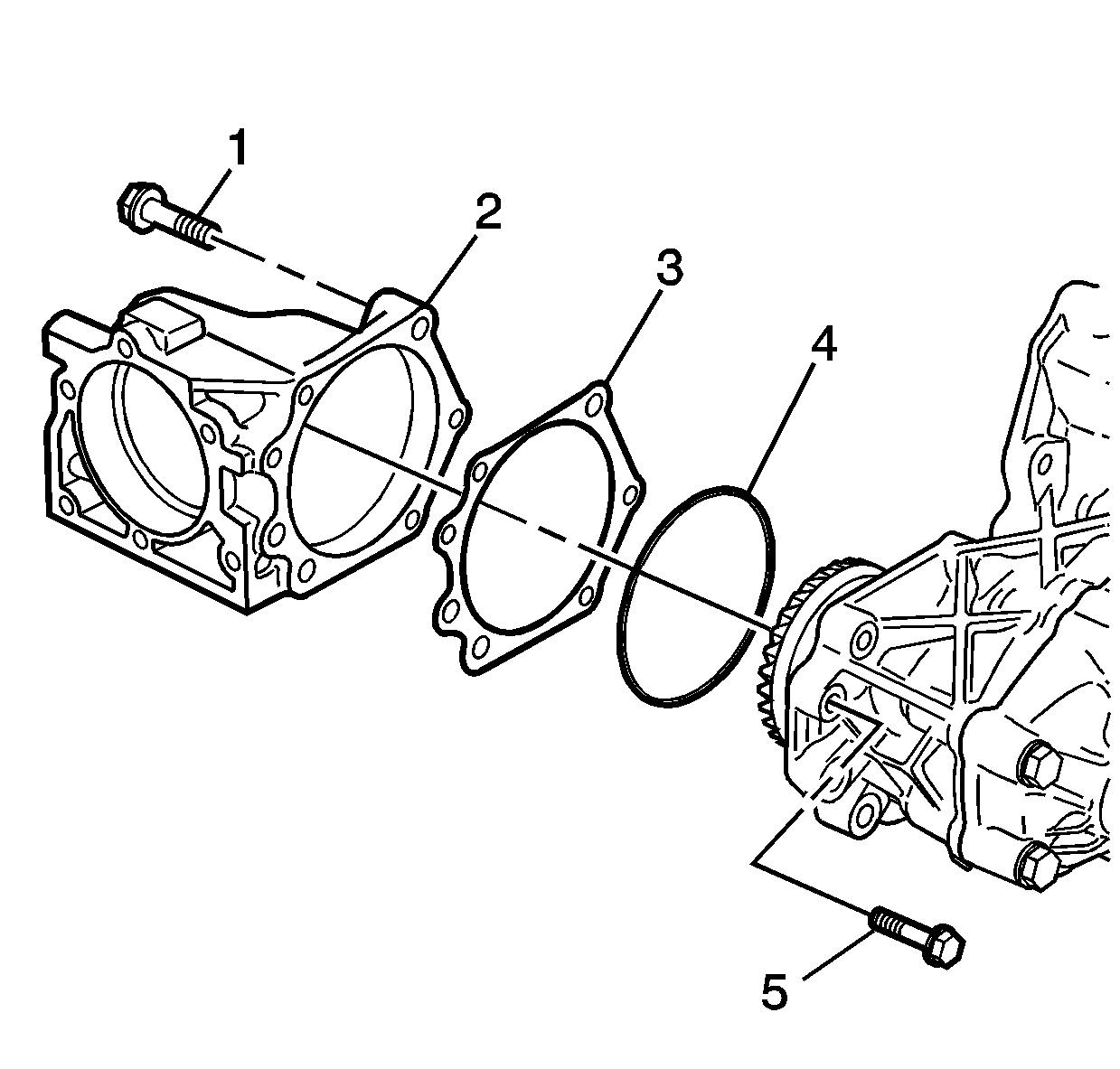
- Remove the bolts (1 and 5), housing (2),
shim (3), and O-ring seal (4) from the left case. Mark or tag
the shim for assembly.
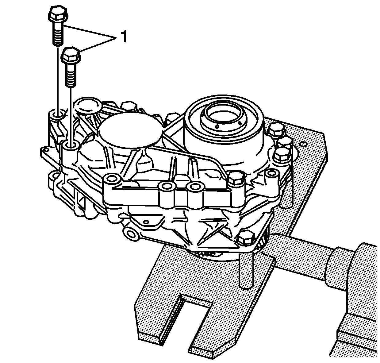
- Remove the bolts (1) from the case.
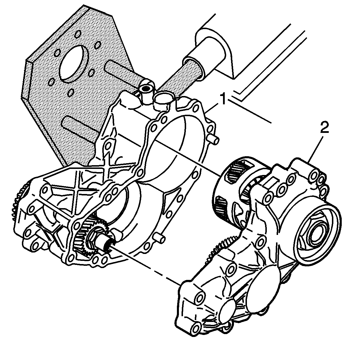
Important: When separating the case halves, avoid damage
to the sealing surfaces. Do not insert a screwdriver or prying tool between the case
sealing surfaces.
- Rotate the
J 44755
90 degrees.
- Separate the right case (2) from the left case (1).
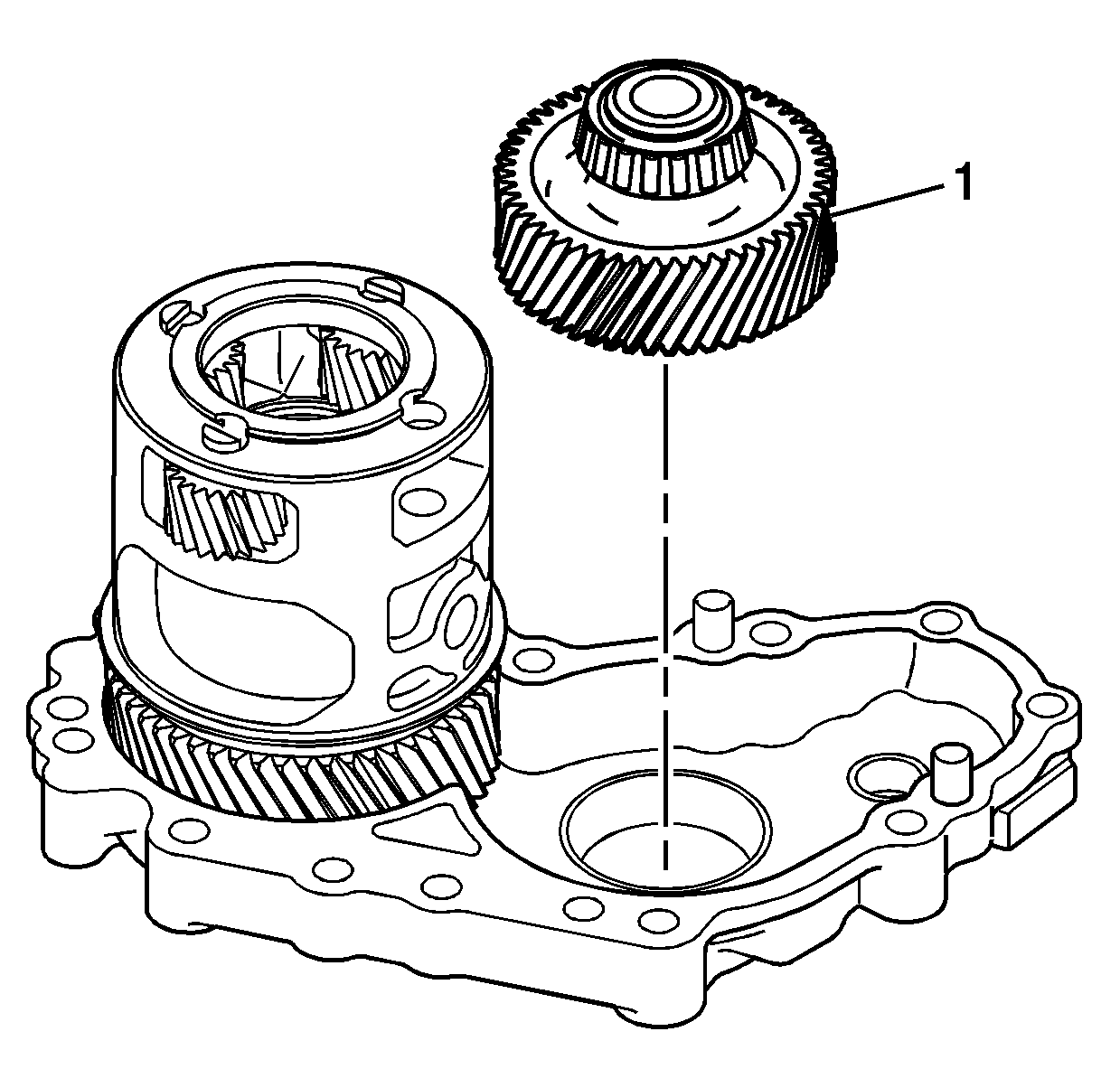
- Remove the idler gear (1) from the
right case.
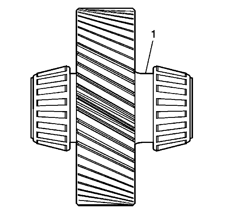
- Note the installed position of the idler
gear. The side of the gear with the longer flange area (1) is to be installed
to the right case.
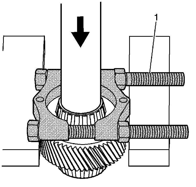
- Install the
J 22912-B
(1) onto the gear (2).
- Position the gear into a press.
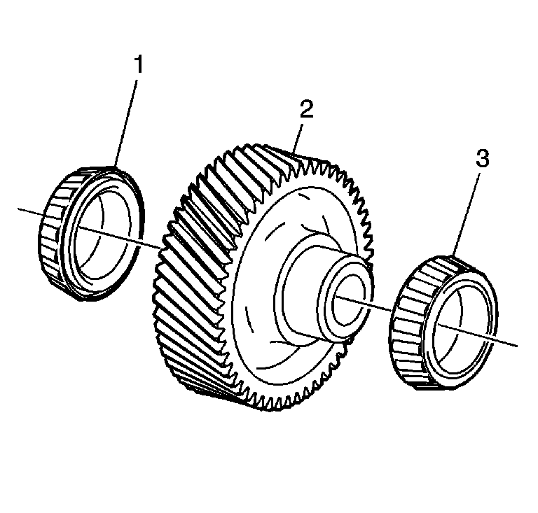
- Remove the bearings (1 and 3) from
the gear (2).
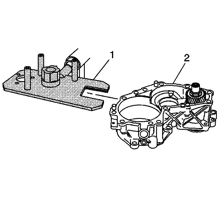
- Install the left case (2) onto the
J 44755
(1). Align the notched
area of the tool with the flat areas of the driveshaft.
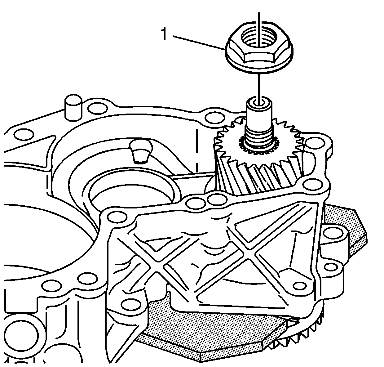
- Remove the nut (1) from the driveshaft.
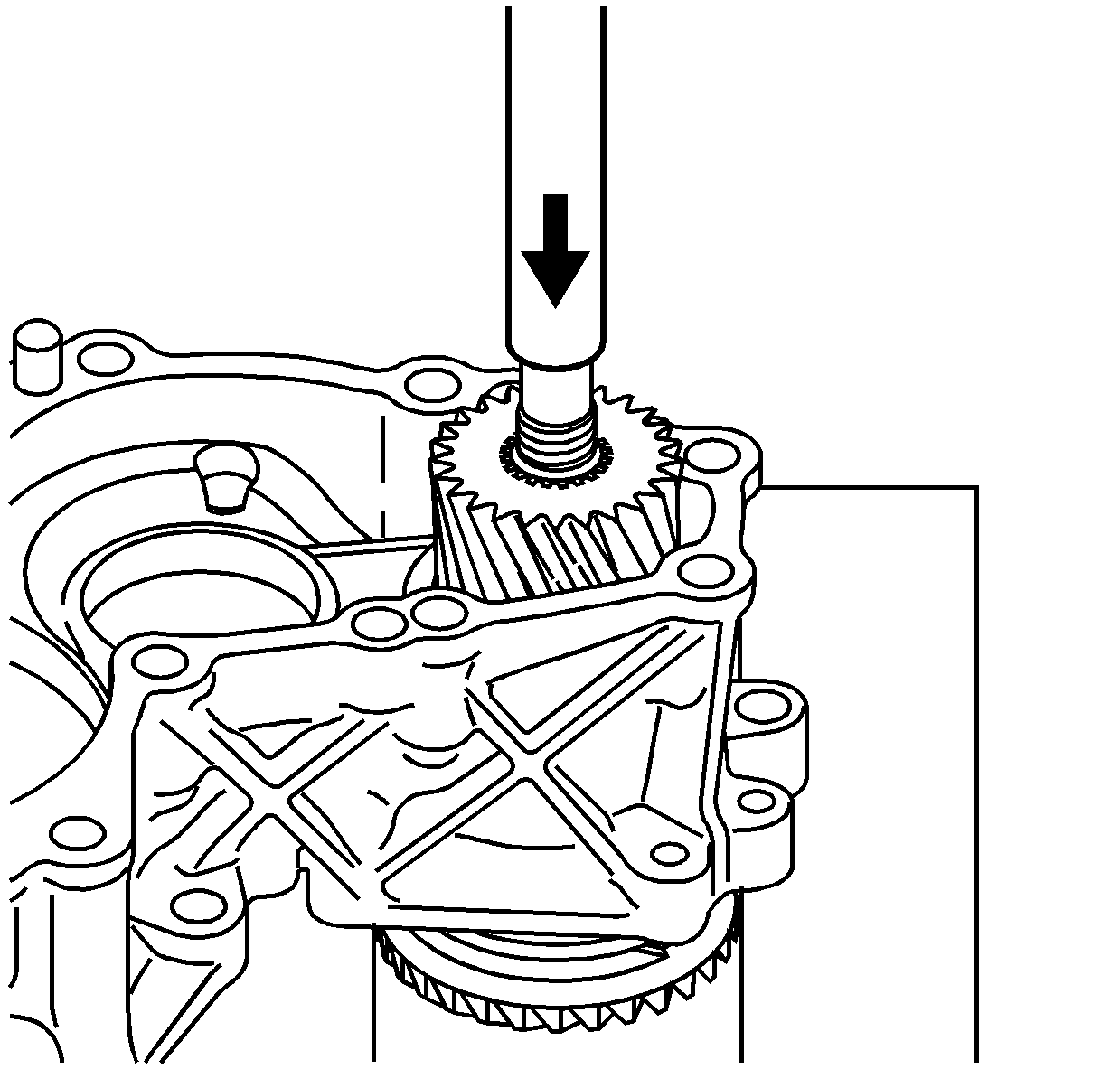
- Position the left case into a press.
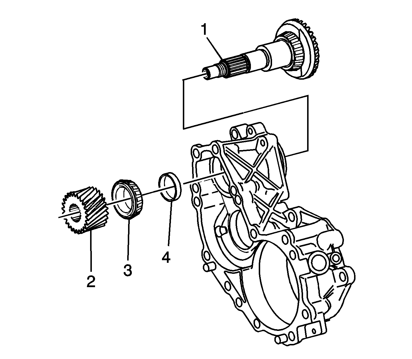
- Remove the gear (2), bearing (3),
shim (4), and shaft (1) from the left case. Mark or tag the shim for
assembly.
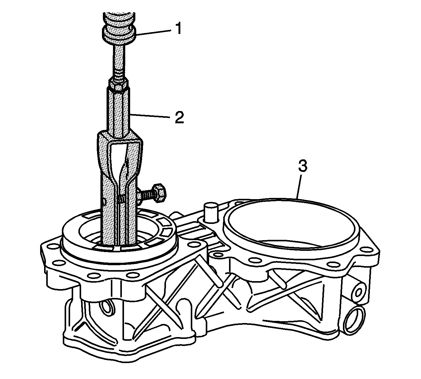
- Use the
J 44380
(2) and the
J 2619-01
(1) in order to remove the outer bearing race from the left case (3).
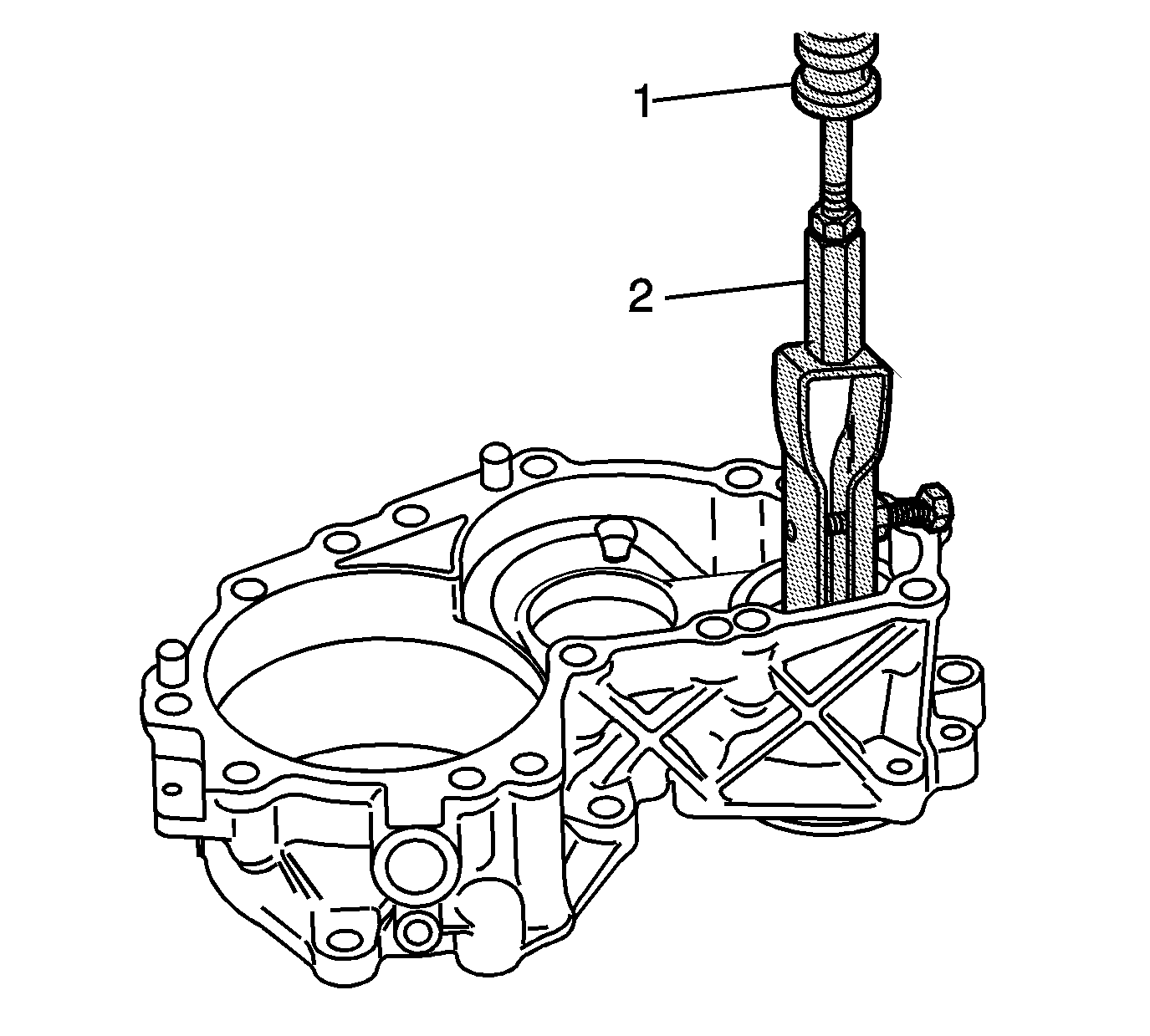
- Remove
the inner bearing race from the left case.
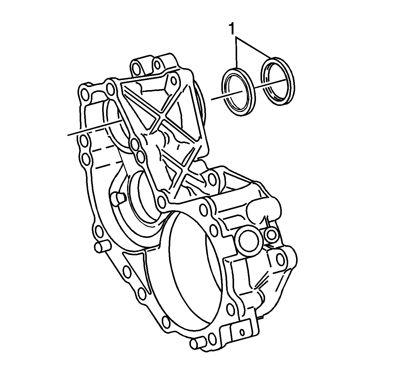
- Remove the oil seals (1) from the
left case.

- Install the
J 22912-B
(1) or equivalent onto the shaft.
- Position the shaft into a press.
- Remove the bearing from the shaft.
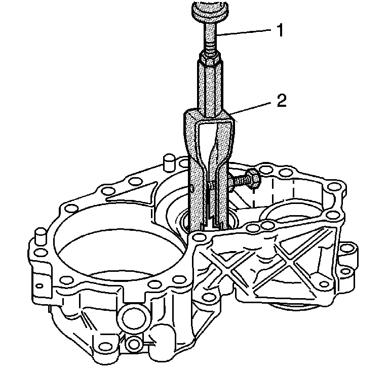
- Install
J 44380
(2) into the left case idler gear bearing race.
- Install
J 2619-01
(1)
to
J 44380
(2).
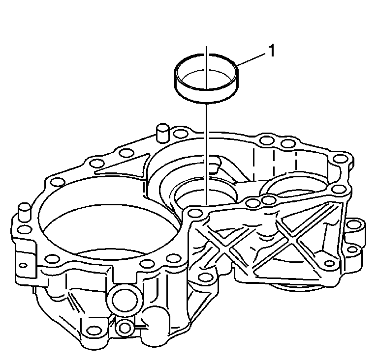
- Remove the idler gear bearing race (1) from the left case.
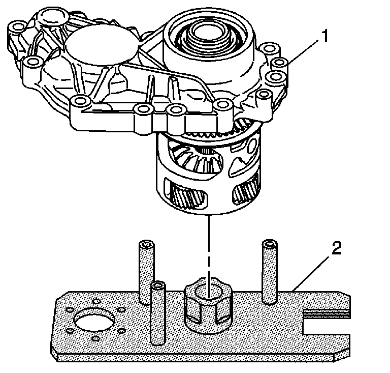
- Install the right case (1) onto the
J 44755
(2). Position the carrier
onto the post of the fixture.
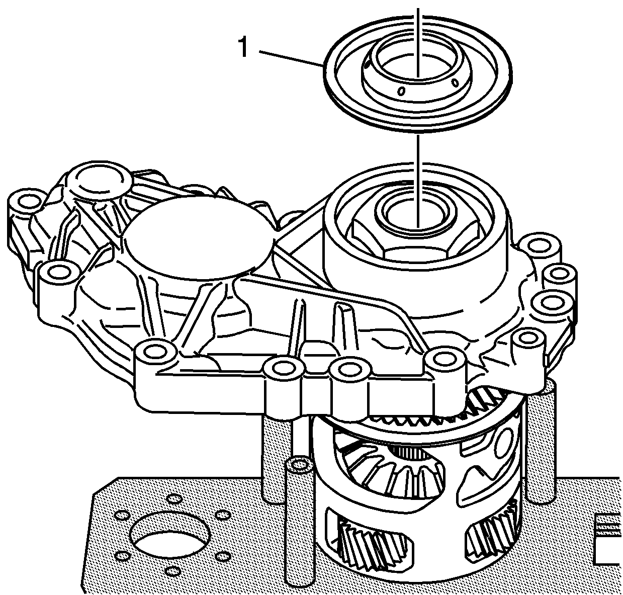
- Remove the oil seal (1) from the
right case.
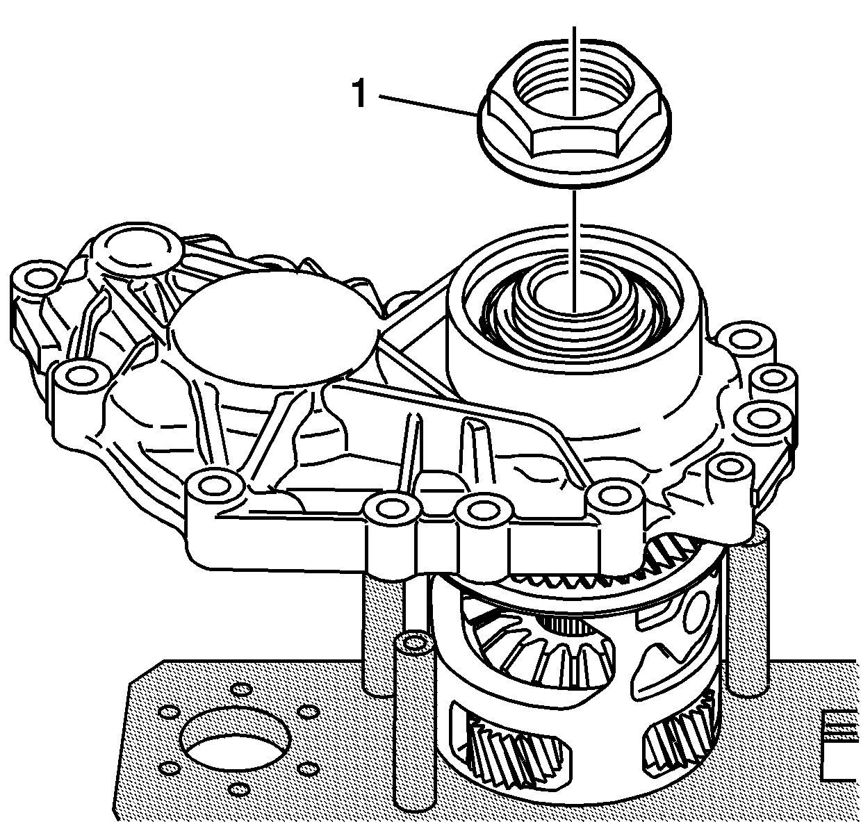
- Remove the nut (1) from the carrier.
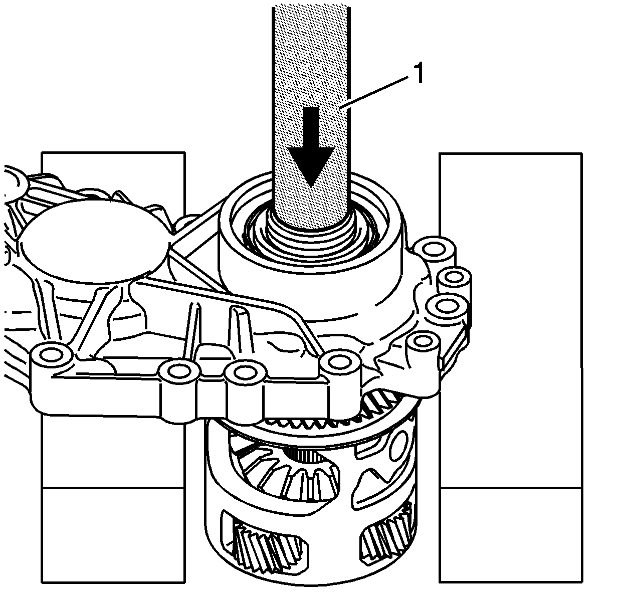
- Position the right case into a press.
- Install the
J 5590
(1)
to the differential carrier.
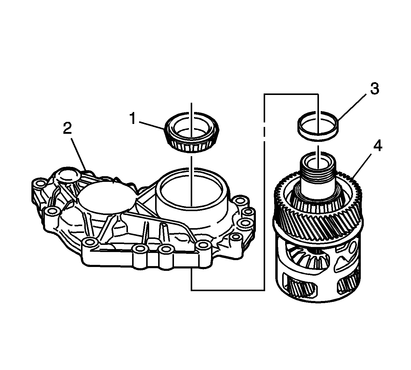
- Remove
the bearing (1), shim (3) and differential carrier (4) from the
right case (2). Mark or tag the shim for assembly.
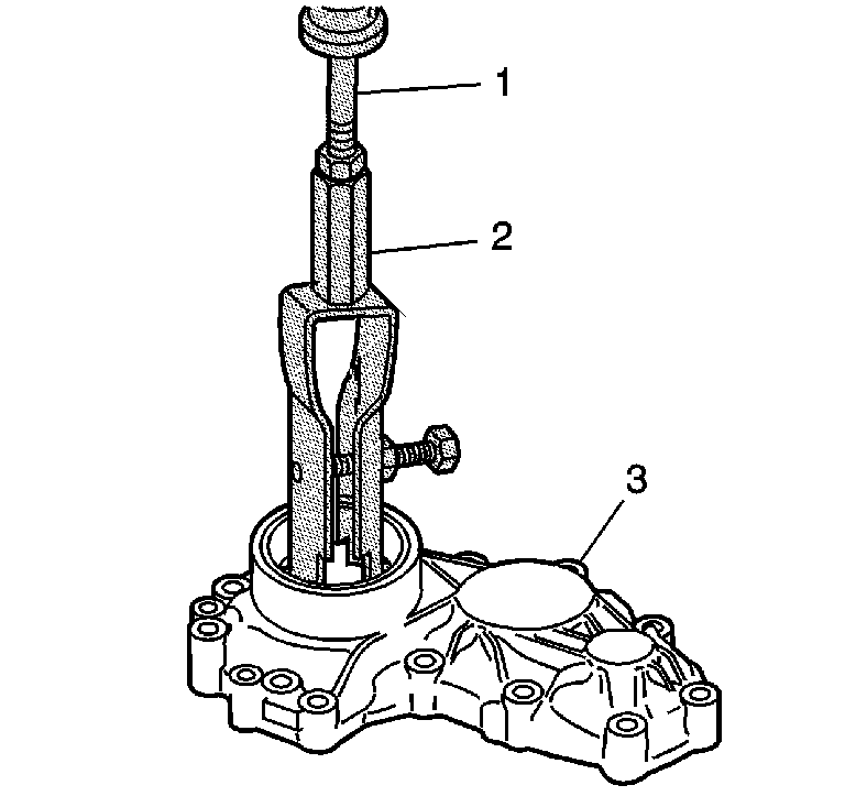
- Use
the
J 44380
(2) and the
J 2619-01
(1) in order
to remove the bearing races from the right case (3), if required.
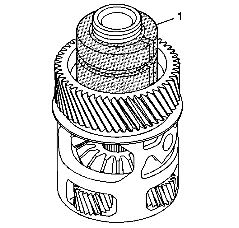
- Install the
J 44754
(1) over the differential carrier bearing.
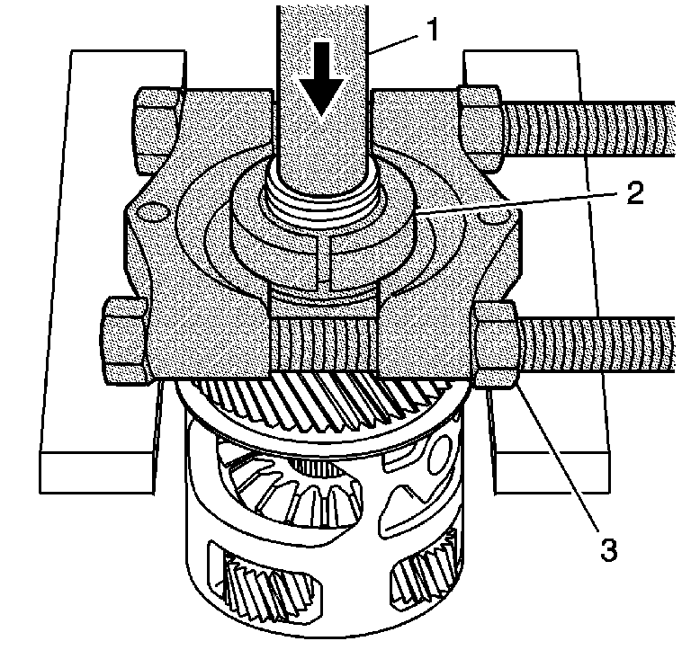
- Install the
J 22912-B
(3) over the
J 44754
(2). Tighten until snug.
- Position the carrier and
J 5590
(1) into a press in order to remove the bearing.
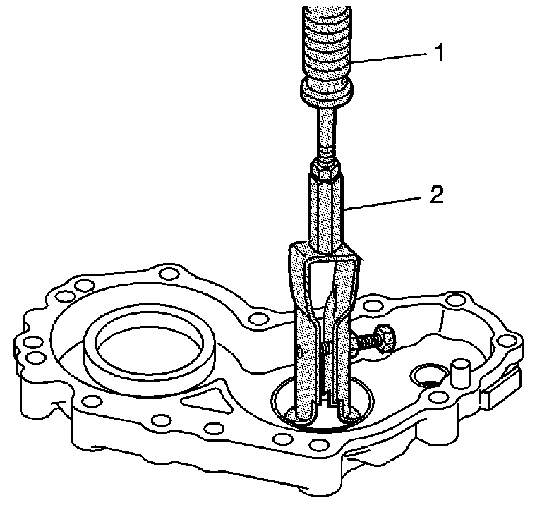
- Install
the
J 44380
(2) into
the right case idler gear bearing race.
- Install
J 2619-01
(1)
to
J 44380
(2).
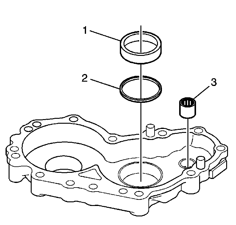
- Remove the bearing race (1) and shim (2).
Mark or tag the shim for assembly.
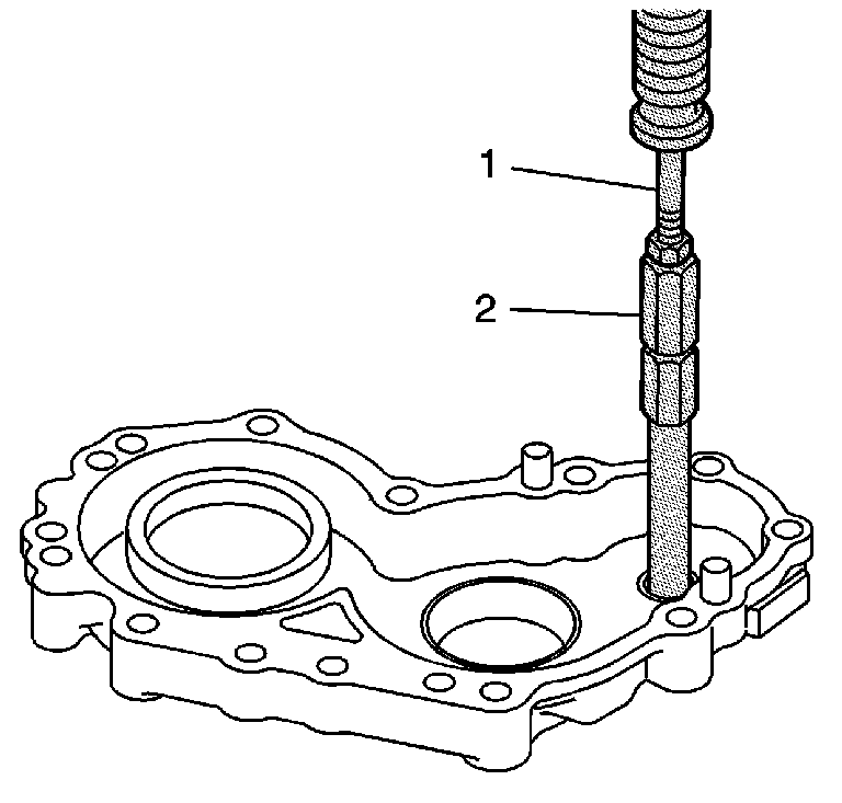
- Install the
J 44737
(2) into the driveshaft bearing. Tighten the tool until snug.
- Install the
J 2619-01
(1)
to the
J 44737
(2).

- Remove the bearing (3) from the right
case.
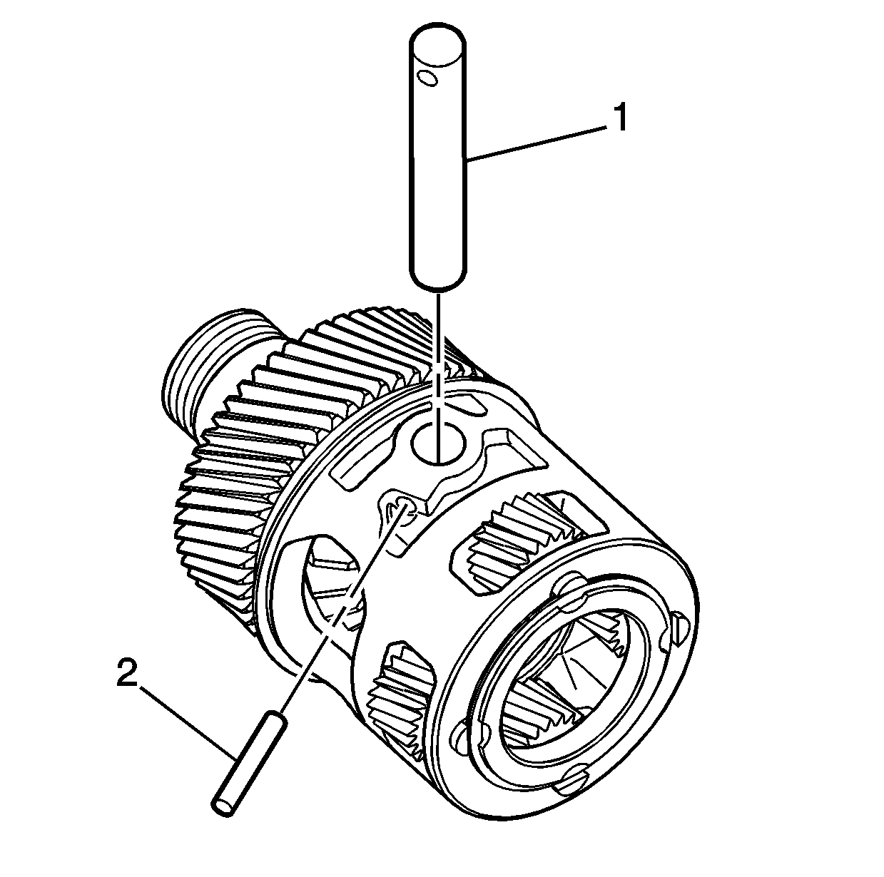
- Remove the roll pin (2) and shaft (1)
from the differential carrier, if required.
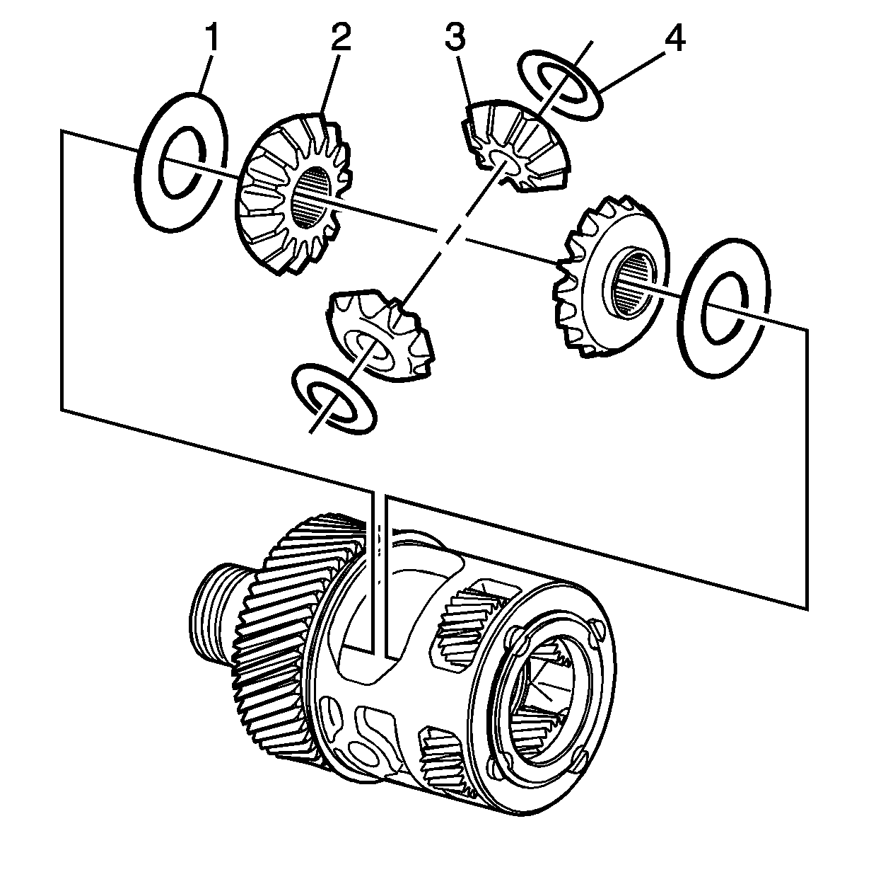
- Remove the side gears (2), pinion
gears (3), and washers (1 and 4) from the carrier, if required.
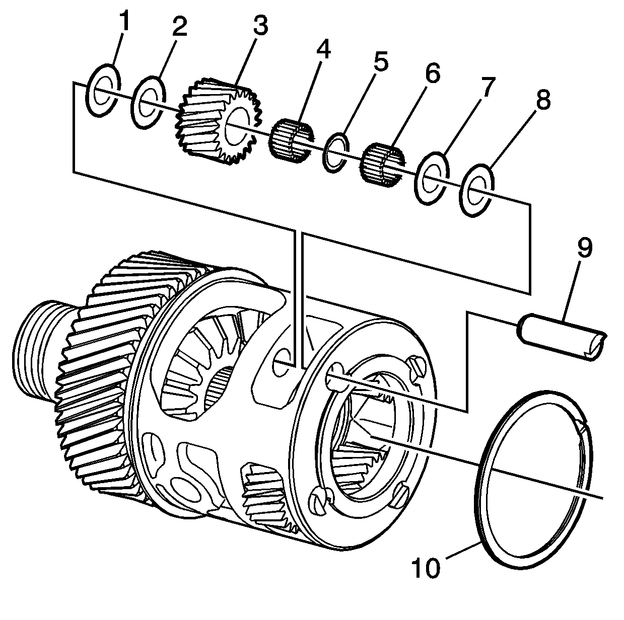
- Remove the ring (10) from the carrier,
if required.
- Remove the pin (9), gear (3) and washers (1, 2, 7, and 8)
from the carrier, if required.
- Remove the needle bearings (4 and 6) and washer (5)
from the gear (3), if required.


