For 1990-2009 cars only
Removal Procedure
- Raise and support the vehicle. Refer to Lifting and Jacking the Vehicle .
- Remove the tire and wheel. Refer to Tire and Wheel Removal and Installation .
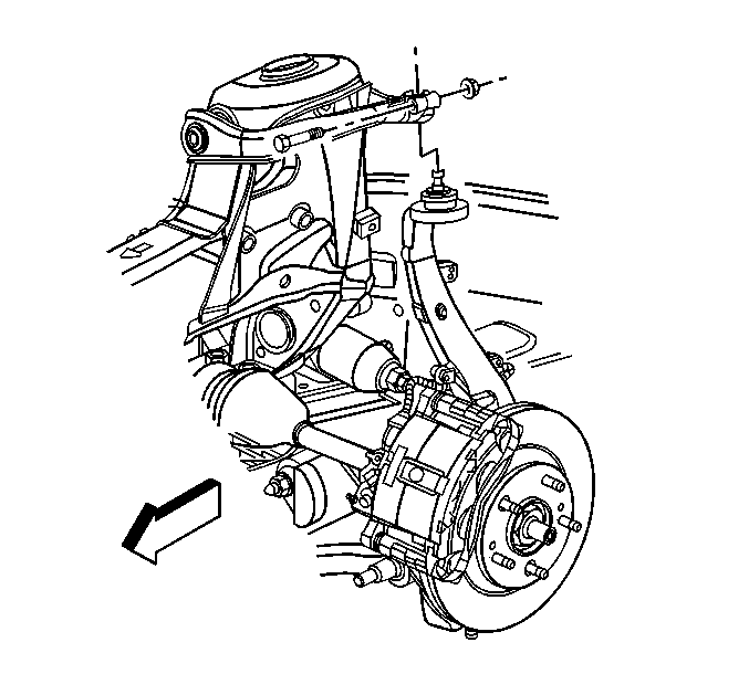
- Remove and discard the upper ball joint to upper control arm bolt and nut.
- Separate the upper control arm from the steering knuckle.
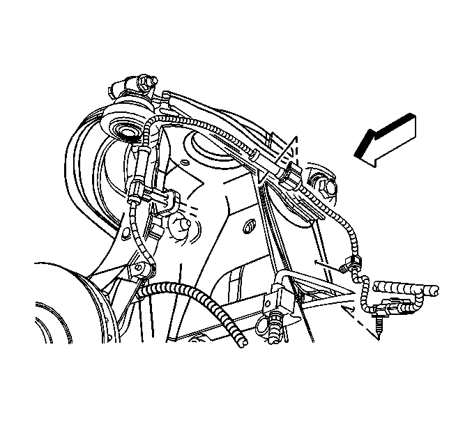
- Remove the wheel speed sensor wiring harness from the upper control arm. Refer to Wheel Speed Sensor Replacement.
- If servicing the left upper control arm, remove the battery tray. Refer to Battery Tray Replacement .
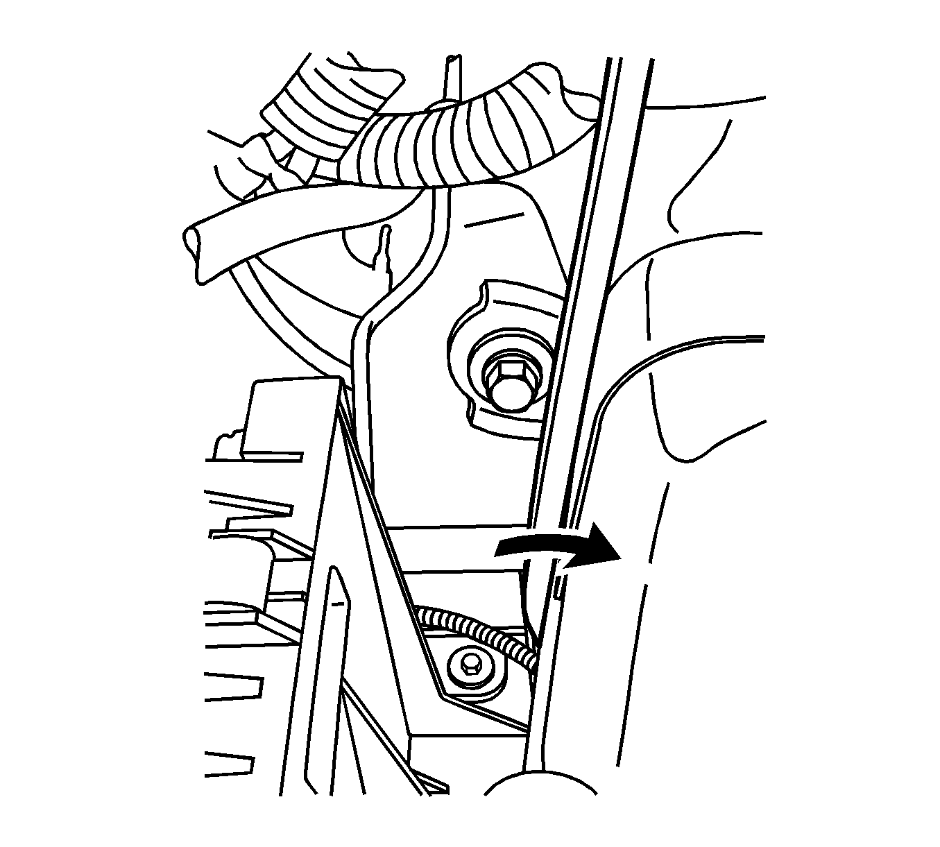
- Gently pry out on inner fender body panel to access forward facing bolt.
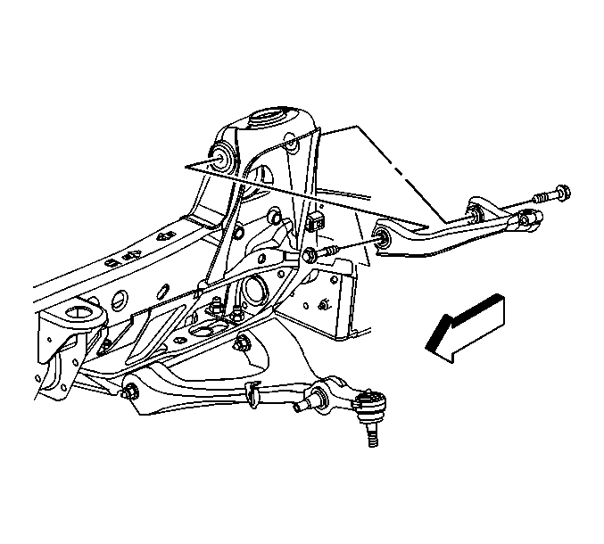
- Remove the upper control arm mounting bolts.
- Remove the upper control arm.


Installation Procedure
- Install the upper control arm.
- Gently pry out on inner fender to access the forward facing bolt.
- Install the upper control arm mounting bolts.
- Install the battery tray, if removed. Refer to Battery Tray Replacement.
- Install the ABS wheel speed sensor wiring harness to the upper control arm. Refer to Wheel Speed Sensor Replacement
- Connect the upper control arm to the steering knuckle.
- Install a new upper ball joint to upper control arm bolt and nut.
- Install the tire and wheel. Refer to Tire and Wheel Removal and Installation .
- Lower the vehicle.
- Check the front wheel alignment. Refer to Wheel Alignment Specifications .


Notice: Refer to Fastener Notice in the Preface section.
Tighten
Tighten the upper control arm mounting bolts to 146 N·m (108 lb ft).

Tighten
Tighten the upper ball joint to upper control arm bolt to 41 N·m (30 lb ft).
