Cooling System Draining and Filling GE 47716 Fill
Tools Required
| • | J 26568 Coolant and Battery Fluid Tester |
| • | GE-47716 Vac N Fill Coolant Refill Tool |
| • | J 42401 Radiator Pressure Adapter |
Draining Procedure
- Place the coolant container under the radiator drain cock located at the bottom of the right radiator end tank.
- Open the drain cock and drain the coolant. A small amount of coolant will drain from the system.
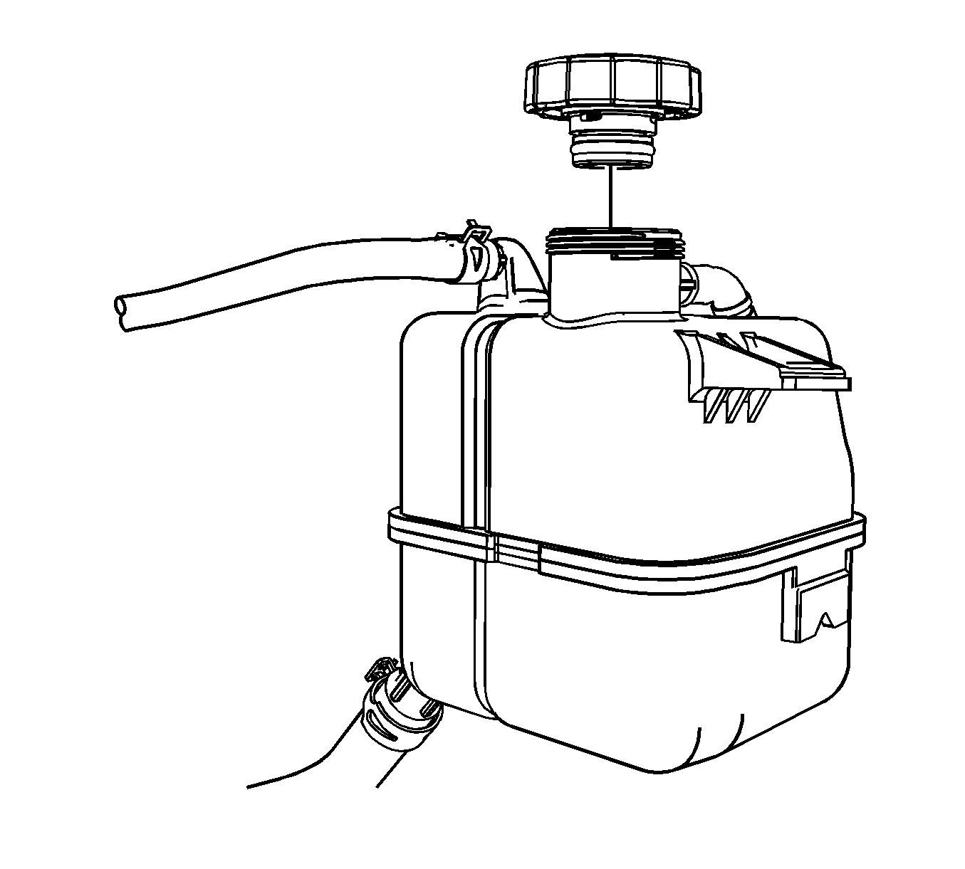
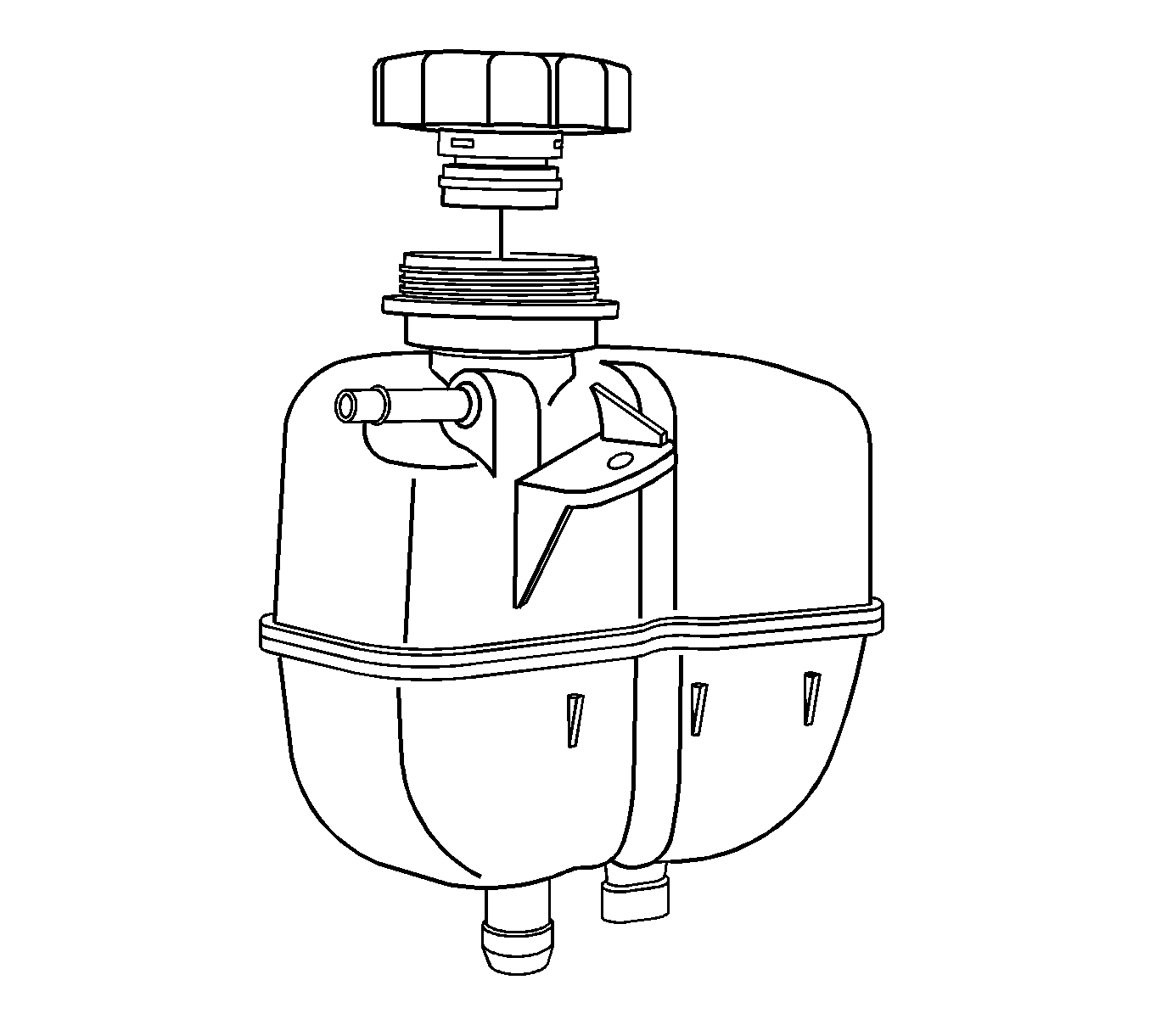
- Remove the surge tank cap from the surge tank and the coolant will drain from the system.
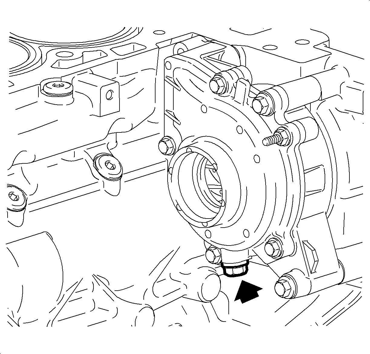
- For LE5 and LAT vehicles, if the engine block needs to be drained, a drain bolt is located near the bottom of the water pump assembly.
- Inspect the coolant.
- Follow the appropriate procedure based on the condition of the coolant.
Caution: In order to avoid personal injury, do not remove the cap or open the cooling system drains from a hot system. Allow the system to cool first.
Important: A 7.6 liter (8 qt) coolant container will be needed.
| • | Normal in appearance--Follow the filling procedure. |
| • | Discolored--Follow the flush procedure. Refer to Coolant System Flushing . |
Vac-N-Fill Procedure
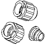
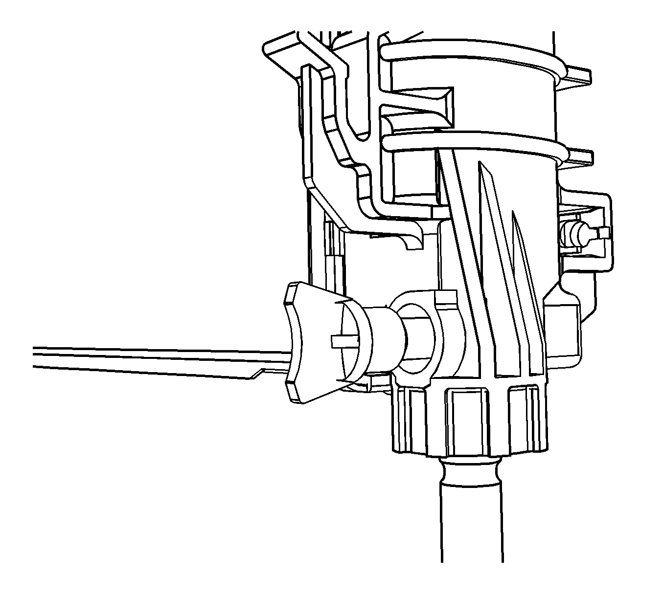
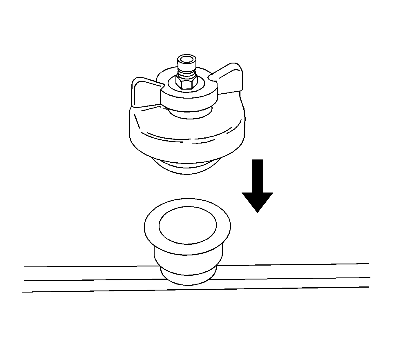
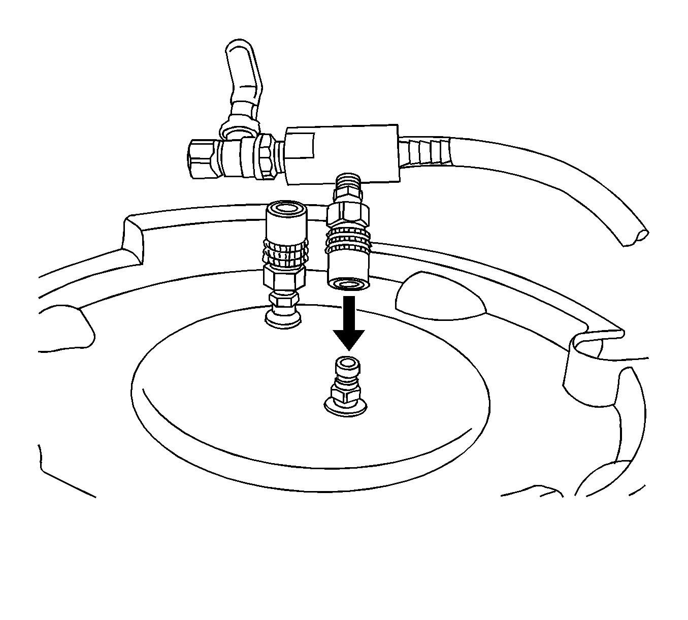
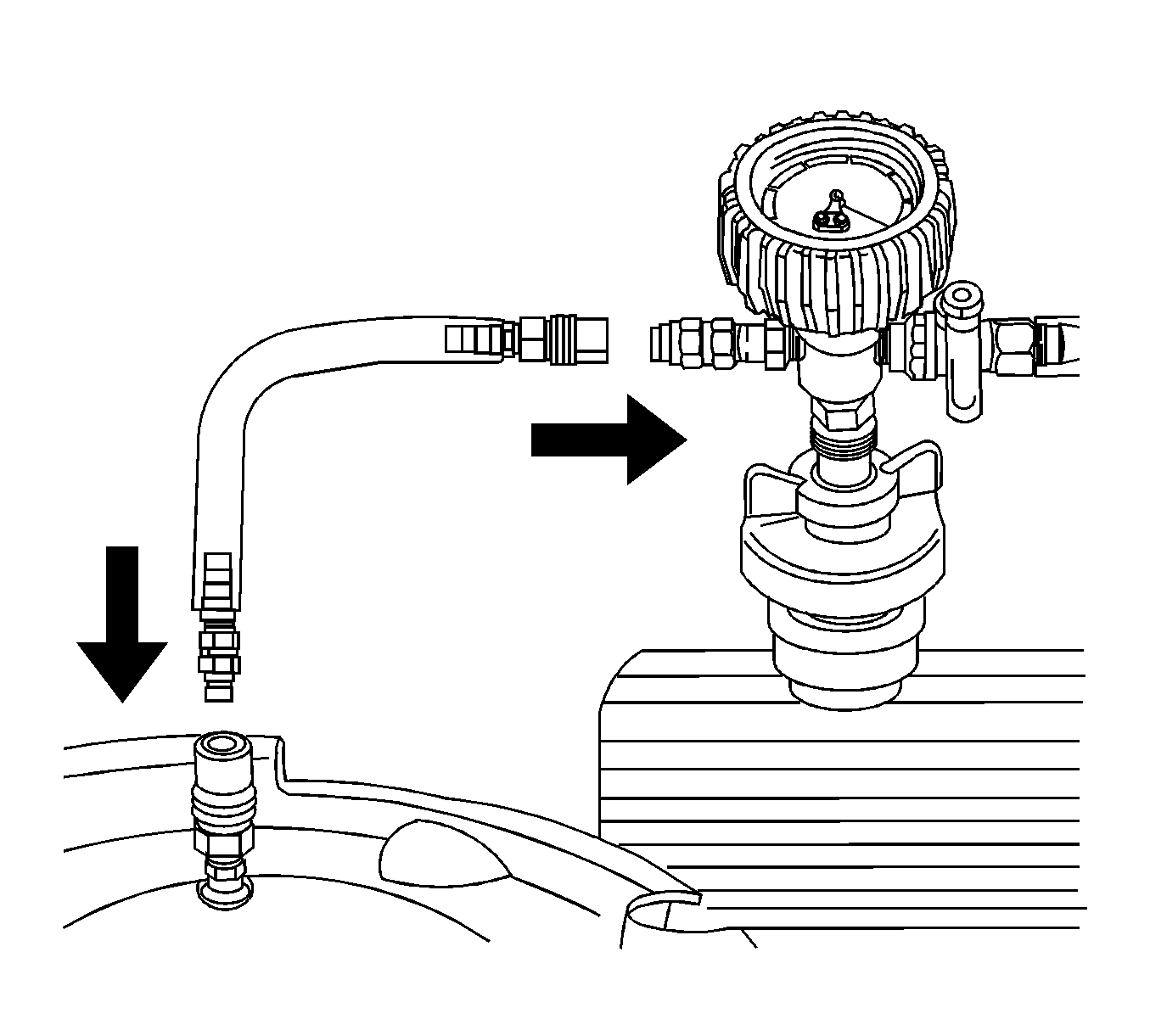
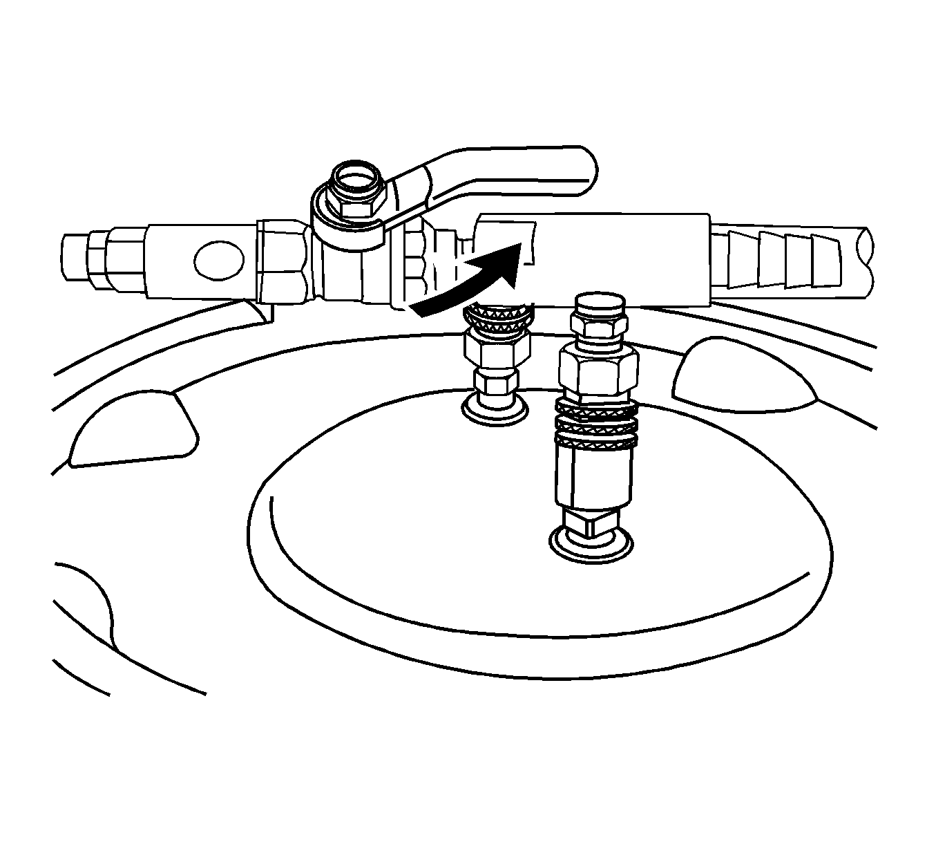
- Install J 42401-2 into the surge tank fill neck.
- Install J 42401-3 to the surge tank fill neck.
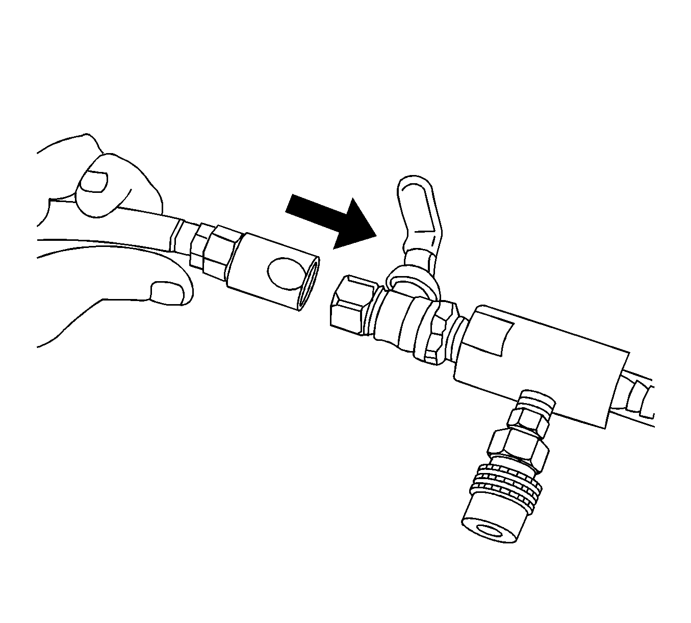
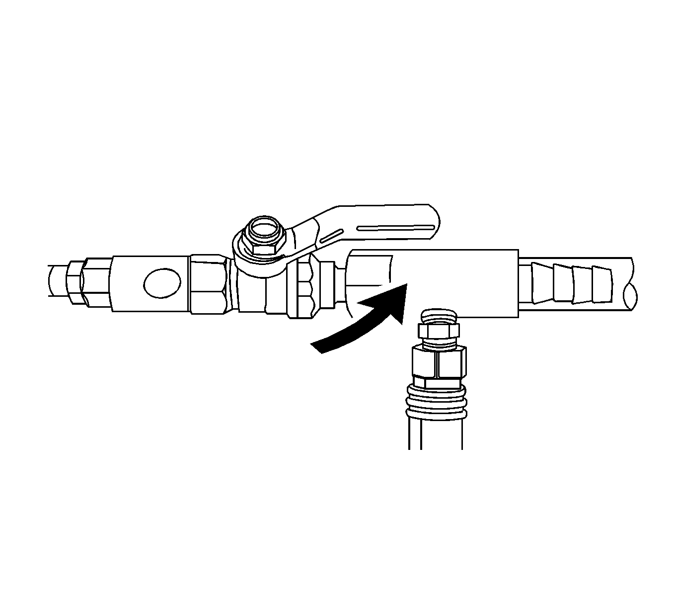
- Attach the Vac N Fill cap to the J 42401-3.
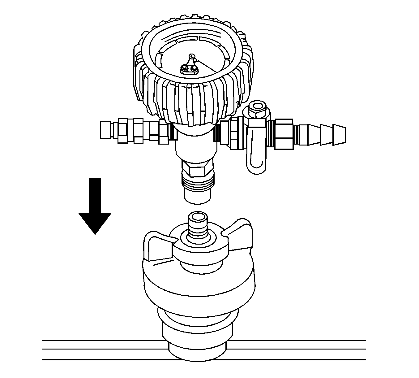
- Attach the vacuum gage assembly to the Vac N Fill cap.
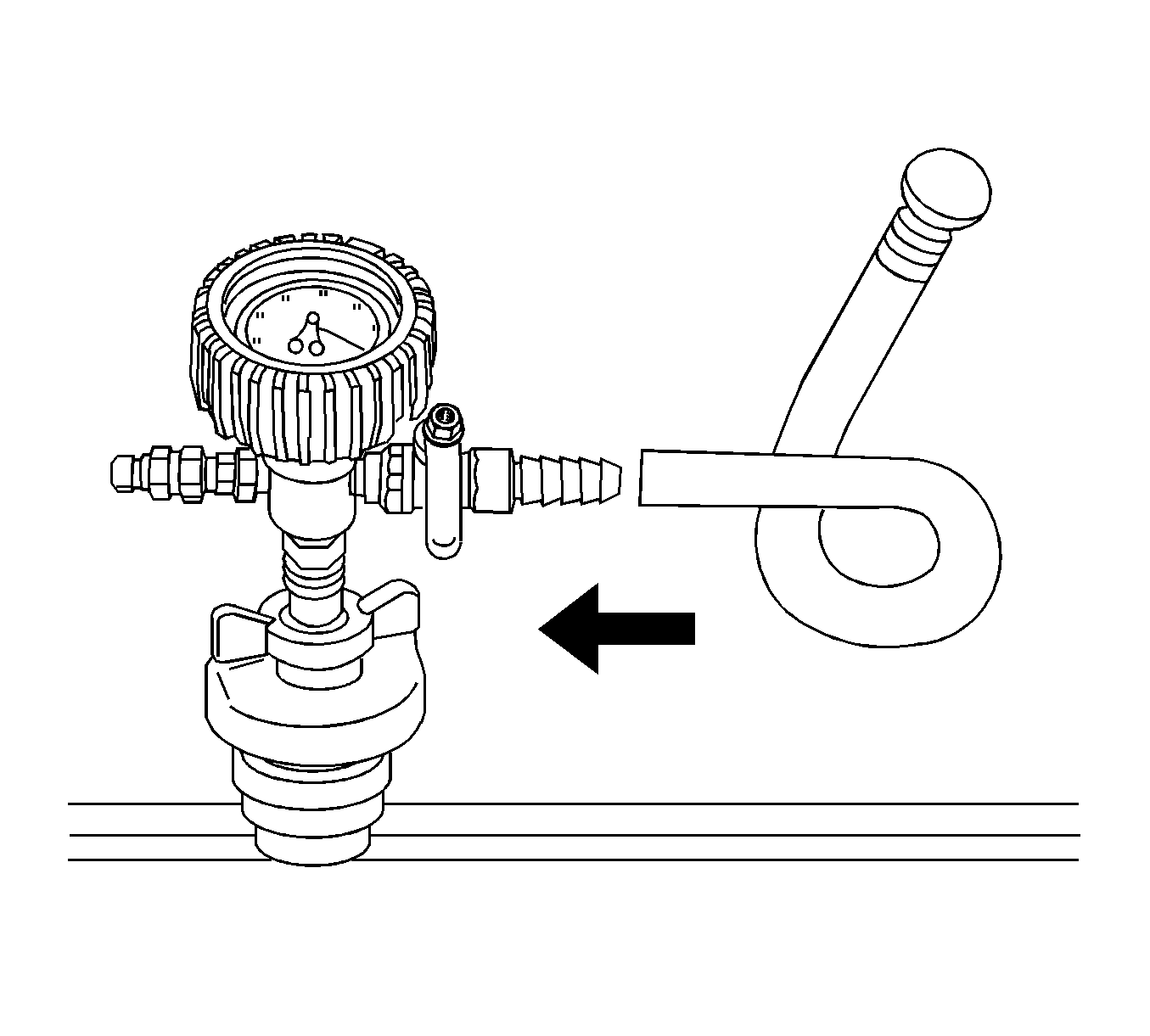
- Attach the fill hose to the barb fitting on the vacuum gage assembly.
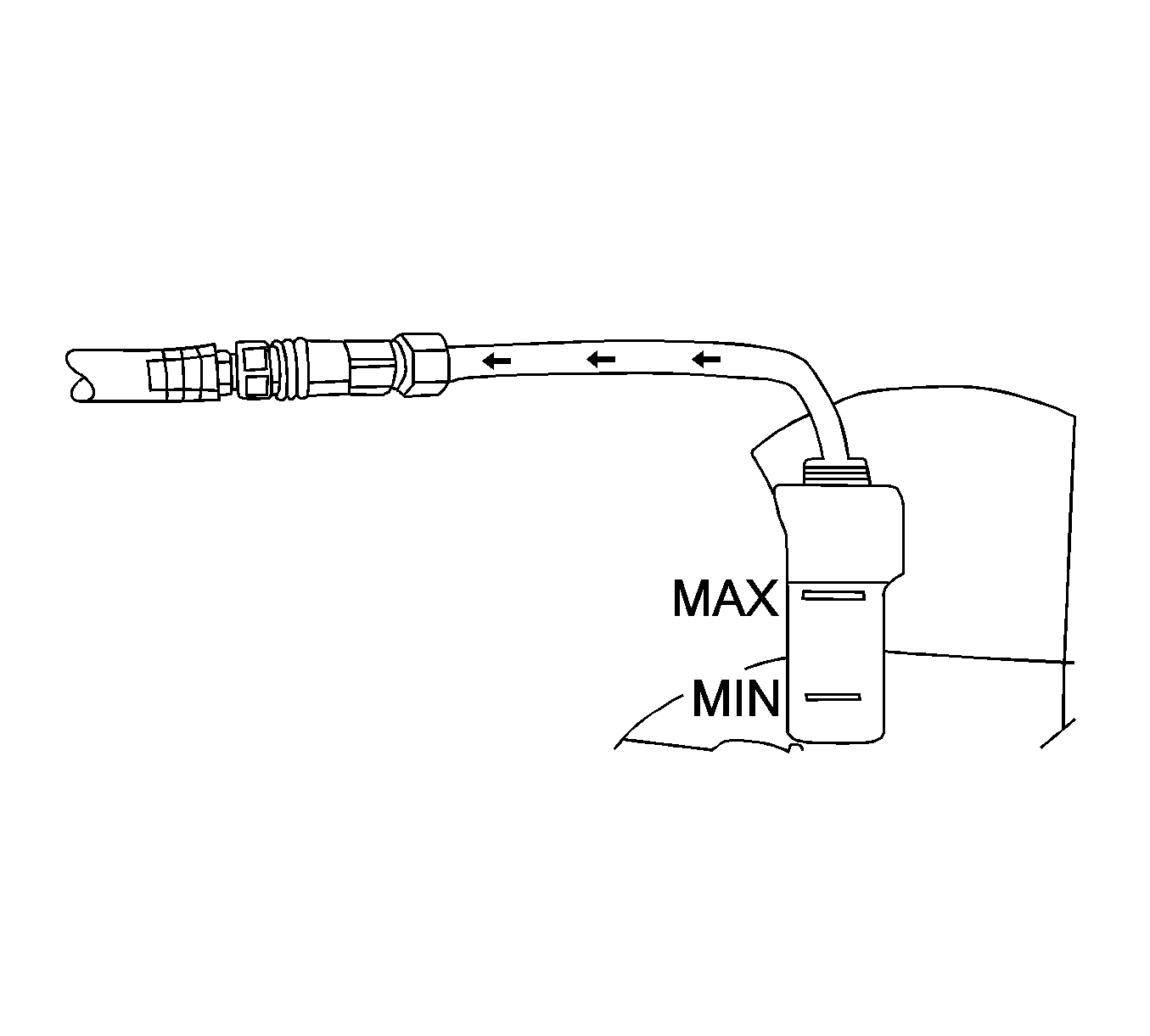
- Pour the coolant mixture into the graduated reservoir.
- Place the fill hose in the graduated reservoir.
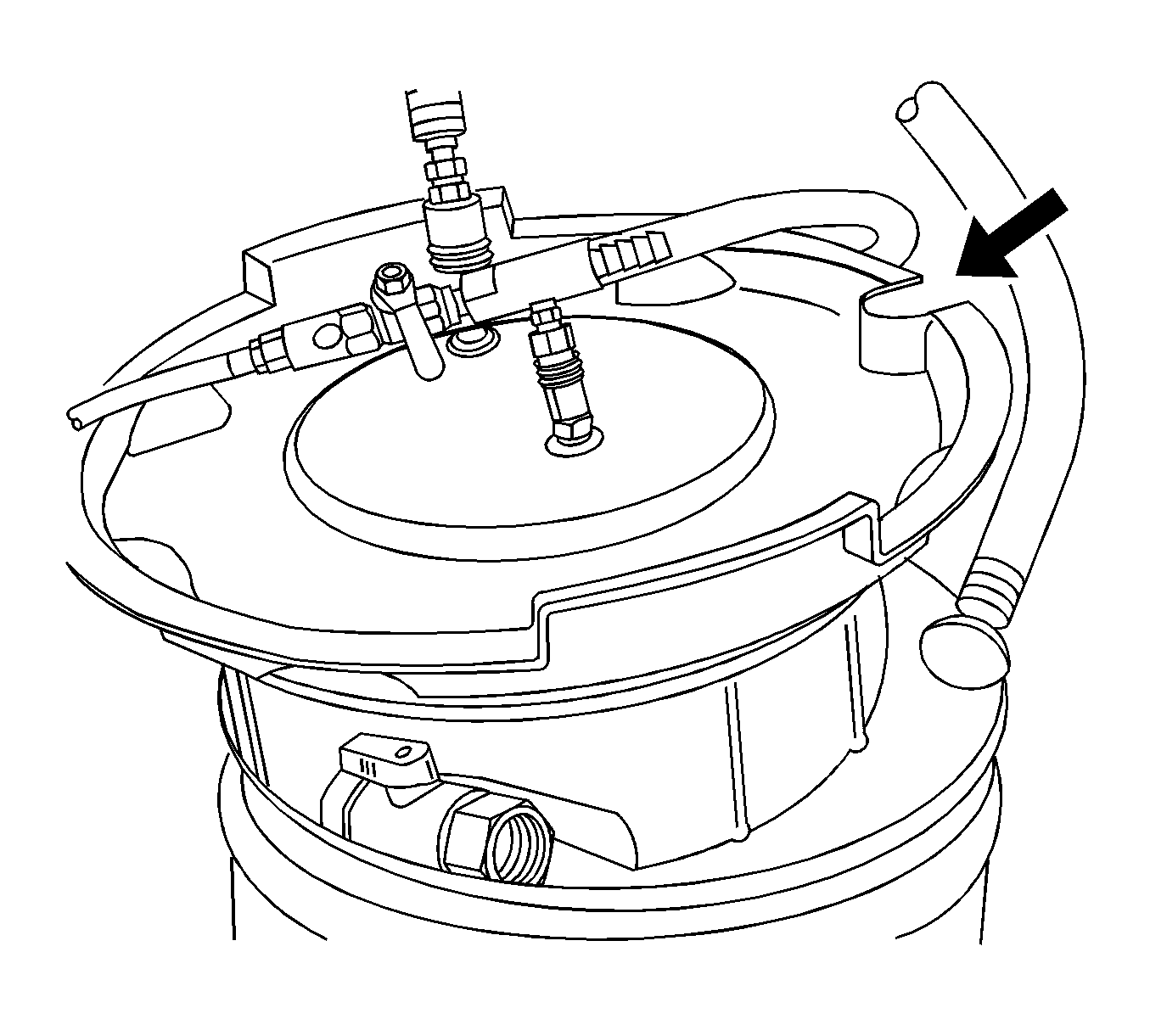
- Install the vacuum tank on the graduated reservoir with the fill hose routed through the cut-out area in the vacuum tank.
- Attach the venturi assembly to the vacuum tank.
- Attach a shop air hose to the venturi assembly.
- Attach the vacuum hose to the vacuum gage assembly and the vacuum tank.
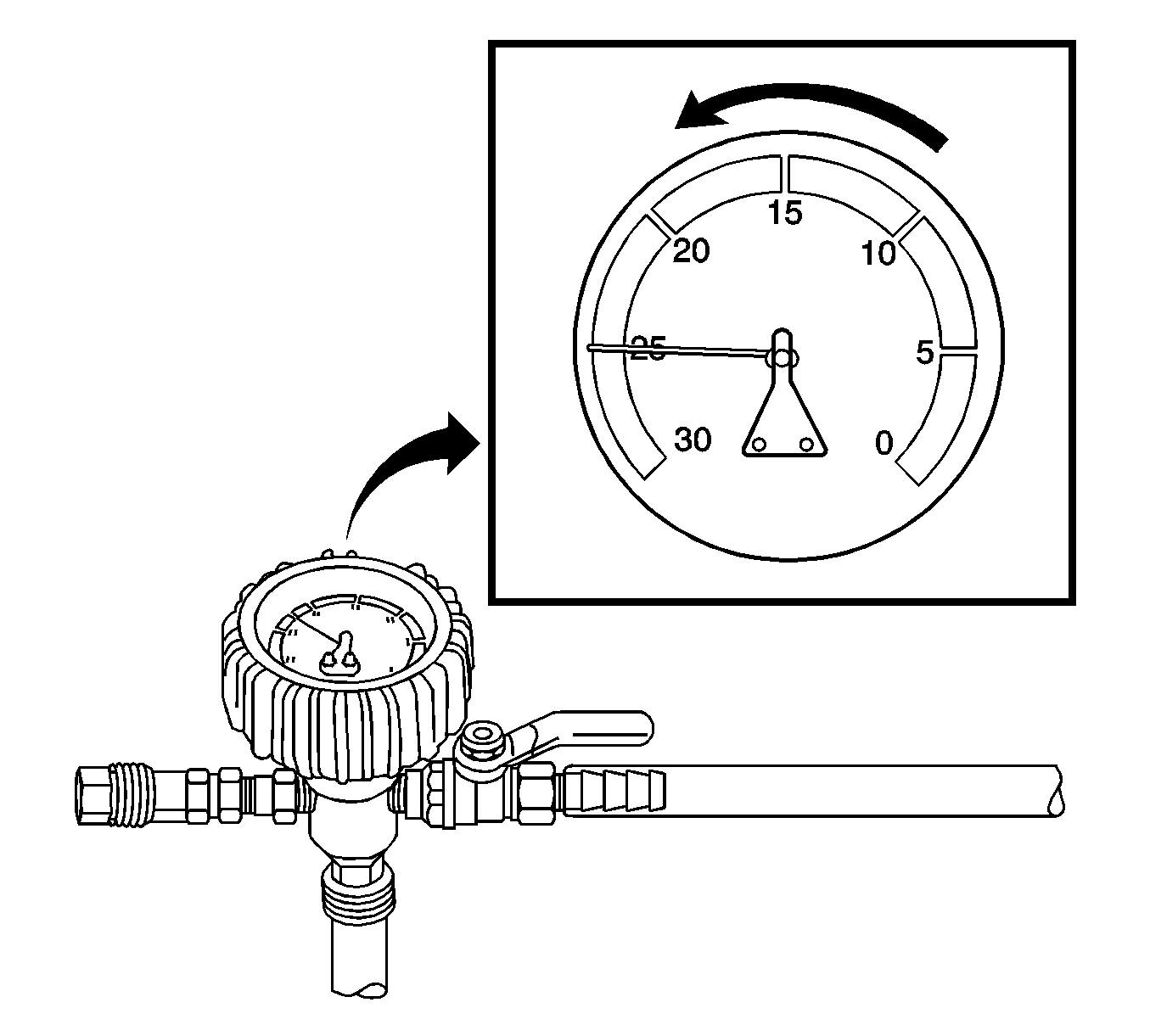
- Open the valve on the venturi assembly. The vacuum gage will begin to rise and a hissing noise will be present.
- Continue to draw vacuum until the needle stops rising. This should be 610-660 mm Hg (24-26 in Hg).
- To aid in the fill process, position the graduated reservoir above the surge tank.
- Slowly open the valve on the vacuum gage assembly. When the coolant reaches the top of the fill hose, close the valve. This will eliminate air from the fill hose.
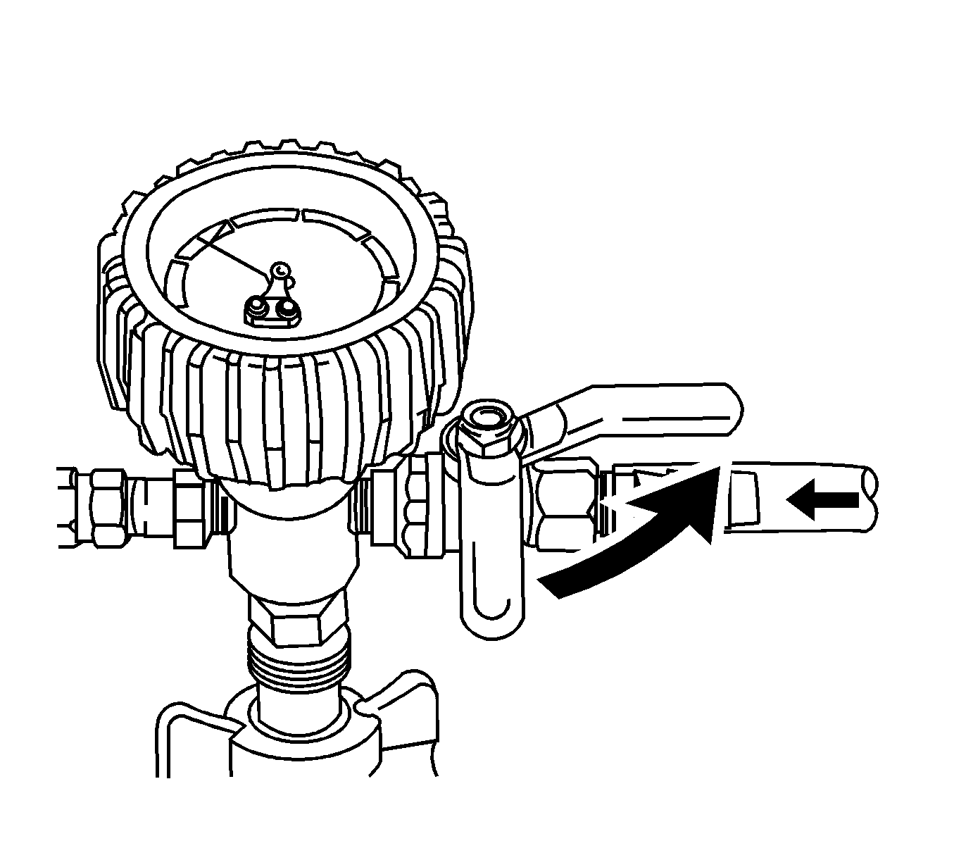
- Close the valve on the venturi assembly.
- If there is a suspected leak in the cooling system, allow the system to stabilize under vacuum and monitor for vacuum loss.
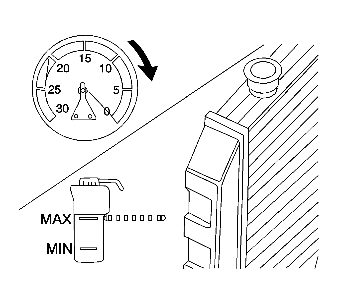
- Open the valve on the vacuum gage assembly. The vacuum gage will drop as coolant is drawn into the system.
- Once the vacuum gage reaches zero, close the valve on the vacuum gage assembly and repeat steps 12-18.
- Detach the Vac N Fill cap from the J 42401-3.
- Remove J 42401-2 from the surge tank fill neck.
- Add coolant to the system as necessary.
- Inspect the concentration of the coolant mixture using J 26568 .
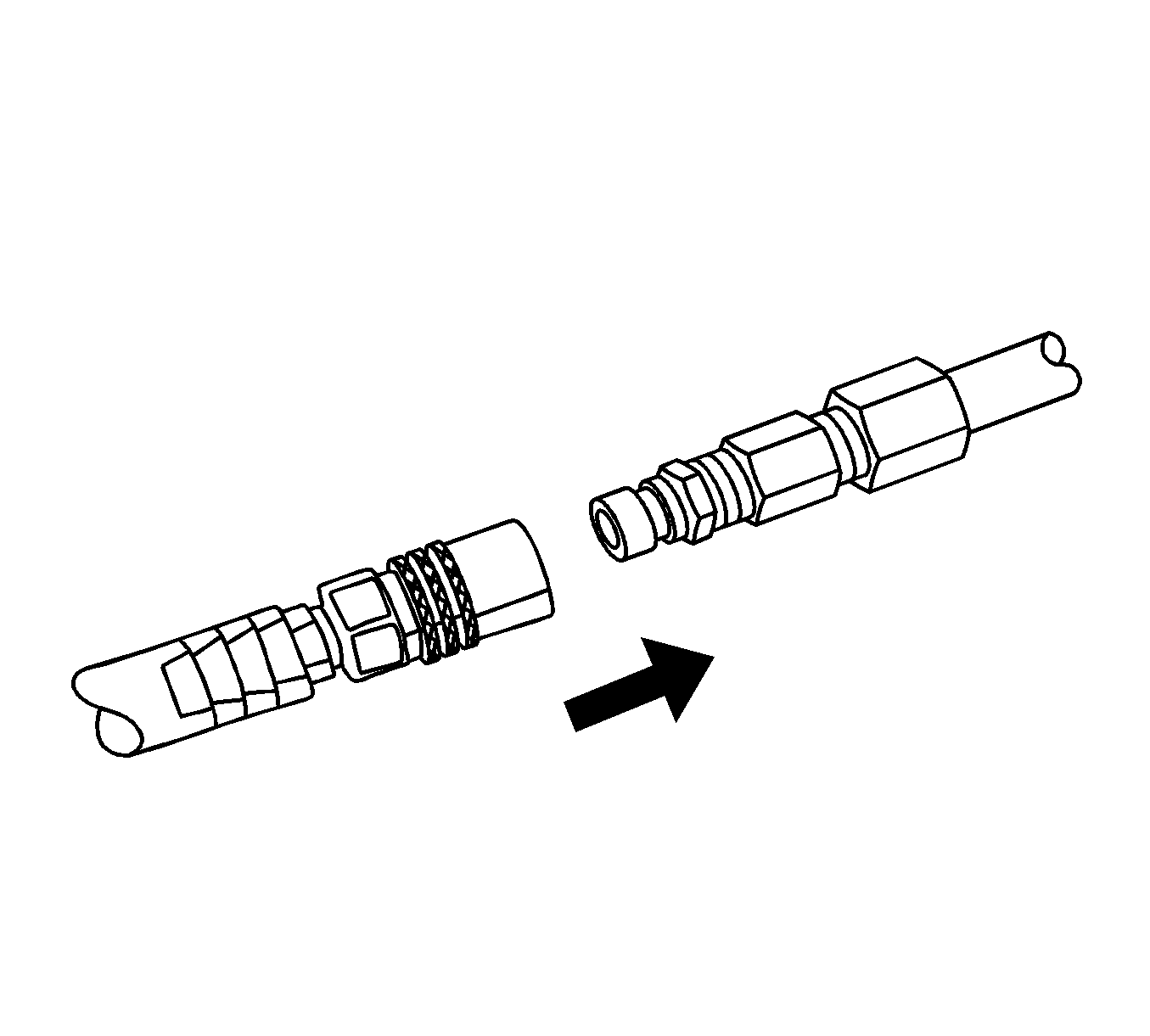
- Detach the vacuum hose from the vacuum gage assembly.
- Attach the extraction hose to the vacuum hose.
- Open the valve on the venturi assembly to start a vacuum draw.
- Use the extraction hose to draw out coolant to the proper level.
- The vacuum tank has a drain valve on the bottom of the tank. Open the valve to drain coolant from the vacuum tank into a suitable container for disposal.
Caution: To avoid being burned, do not remove the radiator cap or surge tank cap while the engine is hot. The cooling system will release scalding fluid and steam under pressure if radiator cap or surge tank cap is removed while the engine and radiator are still hot.
Important: To prevent boiling of the coolant/water mixture in the vehicle’s cooling system, do not apply vacuum to a cooling system above 49°C (120°F). The tool will not operate properly when the coolant is boiling.
Ensure that the valve is closed.
Important: Use a 50/50 mixture of DEX-COOL antifreeze and clean, drinkable water.
Always use more coolant than necessary. This will eliminate air from being drawn into the cooling system.Important: Prior to installing the vacuum tank onto the graduated reservoir, ensure that the drain valve located on the bottom of the tank is closed.
Ensure the valve on the venturi assembly is closed.
Cooling hoses may start to collapse. This is normal due to vacuum draw.
If vacuum loss is observed, refer to Loss of Coolant .
Important: After filling the cooling system, the extraction hose can be used to remove excess coolant to achieve the proper coolant level.
Cooling System Draining and Filling LY7, LZ4, Static Fill
Tools Required
J 26568 Coolant and Battery Fluid Tester
Draining Procedure
Caution: With a pressurized cooling system, the coolant temperature in the radiator can be considerably higher than the boiling point of the solution at atmospheric pressure. Removal of the surge tank cap, while the cooling system is hot and under high pressure, causes the solution to boil instantaneously with explosive force. This will cause the solution to spew out over the engine, the fenders, and the person removing the cap. Serious bodily injury may result.
- Unscrew the surge tank cap to remove vacuum when draining coolant.
- Raise the vehicle. Refer to Lifting and Jacking the Vehicle.
- Remove the engine splash shield. Refer to Engine Splash Shield Replacement
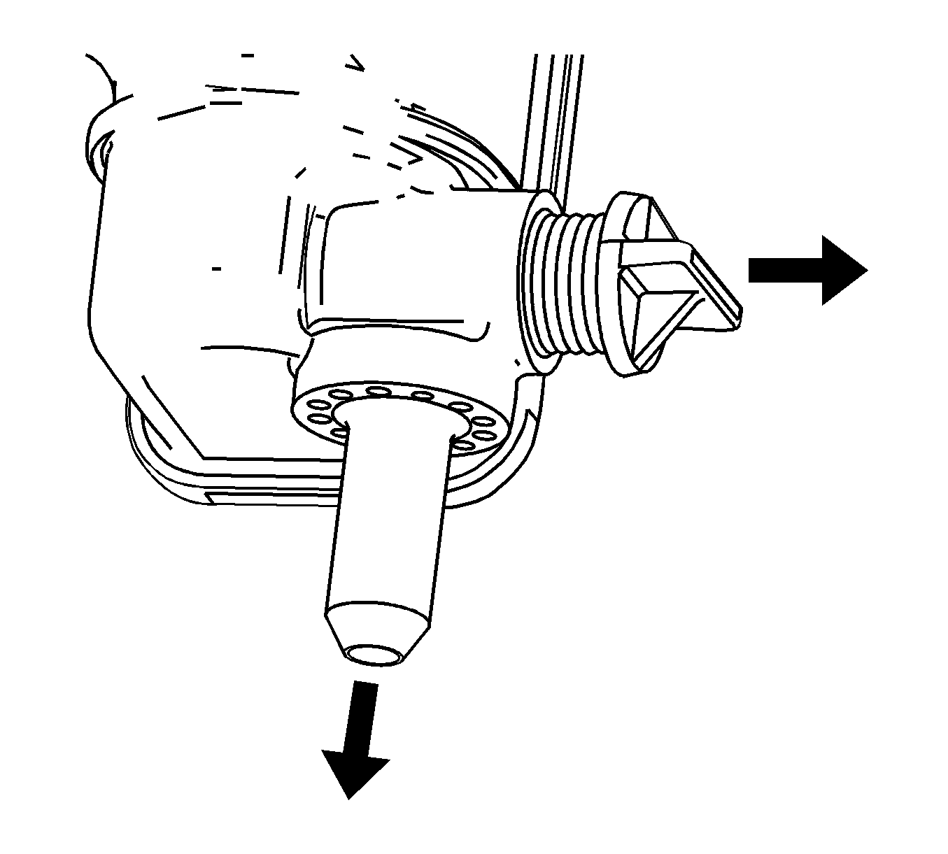
- Place a container under the radiator drain.
- Unscrew the radiator drain plug until coolant flows out the radiator drain.
- If a complete block drain is required, remove the coolant drain plugs. Refer to Draining Fluids and Oil Filter Removal for the 3.5L engine, or Engine Block Disassemblefor the 3.6L engine.
- Follow the appropriate procedure based on the condition of the coolant:
| • | Normal in appearance--Follow the filling procedure. |
| • | Discolored--Follow the flush procedure. Refer to Flushing. |
Fill Procedure
- Install the engine block coolant drain plugs. Refer to the appropriate procedure:
- Close the radiator drain plug.
- Install the engine splash shield. Refer to Engine Splash Shield Replacement
- Lower the vehicle.
- Vehicle should be level.
- Add a mixture of 50/50 DEX-COOL® antifreeze and clean drinkable water until the level stabilizes approximately 25.4 mm (1 in) above the weld seam on the surge tank. Refer to Approximate Fluid Capacities.
- Install the surge tank cap.
- Start the engine and run at 2,000 RPM until the engine cooling fans turn ON.
- Turn the engine OFF and allow the engine to cool down.
- Remove the surge tank cap.
- Refill to approximately 25.4 mm (1 in) above the weld seam on the surge tank.
- Install the surge tank cap.
- Inspect the concentration of the engine coolant using J 26568 .
- Inspect the concentration of the engine coolant using J 26568 .
- Install the surge tank cap.
- Rinse away any excess coolant from the engine and the engine compartment.
Notice: The procedure below must be followed. Improper coolant level could result in a low or high coolant level condition, causing engine damage.
| • | Engine Block Assemble for the 3.5L engine. |
| • | Engine Block Assemble for the 3.6L engine. |
Important: DO NOT exceed 2,200 RPM.
Cooling System Draining and Filling LAT Static Fill
Tools Required
J 26568 Coolant and Battery Fluid Tester
Draining Procedure
Caution: With a pressurized cooling system, the coolant temperature in the radiator can be considerably higher than the boiling point of the solution at atmospheric pressure. Removal of the surge tank cap, while the cooling system is hot and under high pressure, causes the solution to boil instantaneously with explosive force. This will cause the solution to spew out over the engine, the fenders, and the person removing the cap. Serious bodily injury may result.
- Unscrew the surge tank cap to remove vacuum when draining coolant.
- Raise the vehicle. Refer to Lifting and Jacking the Vehicle .
- Place a container under the radiator drain.
- Unscrew the radiator drain plug until coolant flows out the radiator drain.
- If a complete block drain is required, remove the coolant drain plugs. Refer to Draining Fluids and Oil Filter Removal .
- Follow the appropriate procedure based on the condition of the coolant:
| • | Normal in appearance--Follow the filling procedure. |
| • | Discolored--Follow the flush procedure. Refer to Flushing . |
Fill Procedure
- Install the engine block coolant drain plugs. Refer to Engine Block Assemble .
- Close the radiator drain plug.
- Lower the vehicle.
- Vehicle should be level.
- Slowly add a mixture of 50/50 DEX-COOL® antifreeze and clean drinkable water until the level stabilizes approximately 50.8 mm (2 in) above the weld seam on the surge tank. Refer to Approximate Fluid Capacities .
- Start the engine. The coolant level in the surge tank will drop.
- Continue filling the surge tank as necessary to maintain the level at the cold fill mark.
- When the coolant in the upper radiator hose feels warm, install the surge tank cap.
- Continue to run the engine at 2,000 RPM until the engine cooling fans turn ON.
- Let the engine idle for 30 seconds.
- Turn the engine OFF and allow the engine to cool down.
- Adjust the coolant level.
- Inspect the concentration of the engine coolant using J 26568 .
- Rinse away any excess coolant from the engine and the engine compartment.
Notice: The procedure below must be followed. Improper coolant level could result in a low or high coolant level condition, causing engine damage.
Important: Do not overfill and allow the coolant to cover the surge tank inlet hose port.
Important: DO NOT exceed 2,200 RPM.
Important: Coolant should be at the full cold mark when the system cools.
