General Guide to Panoramic Sunroof Noise Issues (WPC P/N 401)

| Subject: | General Guide to Panoramic Sunroof Noise Issues (WPC P/N 401) |
| Models: | 2005-2007 Pontiac G6 |
| 2007 Saturn Aura |
This bulletin is being revised to update the Parts information. Please discard Corporate Bulletin Number 05-08-67-014J (Section 08 - Body and Accessories).
Important: The intent of this bulletin is to identify the appropriate issue(s) and apply the appropriate correction(s) pertaining to the customer's comments. To determine the final service labor operation time, use the initial base time and then apply the appropriate add times, depending on the issue correction(s) performed. Please note - only the items performed on the vehicle being serviced should be used as the final repair time and the Repair Order must indicate the Bulletin Number and the Condition Number(s) used.
Important: Do not replace an entire sunroof module for creak/pop type noise or wind noise-type complaints. A new sunroof module does not come as a complete assembly and will require many components - including all of the glass panels - to be swapped over from the old module to the new module being installed. Correctly following the bulletin should correct these concerns.
Important: U.S. Dealer Technicians - Please review Tech Assist video 50250.17T1 at the GM Training web site prior to any repair of the panoramic sunroof system.
PLEASE VERIFY CUSTOMER CONCERN BEFORE SERVICE.
Important: If the sunroof motor/actuator assembly has been replaced, or has lost battery positive voltage or ground for any other reason, it will be necessary to initialize the motor/actuator when service has been completed. Refer to Sunroof Control Module Programming and Setup in Programming and Setup.
This bulletin covers the following issues:
| • | Creak/snap/pop type noise coming from the sunroof module - Install mylar washers and lubricate all module fasteners (Refer to Condition #1) |
| • | Windnoise coming from sunroof glass panels and/or HVAC blower whistle type noise that changes with fan speed - Install glass panel cross car foam (Refer to Condition #2) |
| • | Windnoise coming from the sunroof module seal to roof - Install updated module seal (Refer to Condition #3) |
| • | Glass panel loose/rattling - (Refer to Condition #4) |
| • | Plastic/metal rattle type noise coming from the rear area of the sunroof module - (Refer to Condition #5) |
| • | Sunshade will not cycle (open or close) - (Refer to Condition #6) |
| • | Seal itch between glass panels - (Refer to Condition #7) |
| • | Intermittently the sunroof closes while opening - (Refer to Condition #8) |
| • | Light coming through at the rear corner of the glass panels - (Refer to Condition #9) |
| • | Headliner itch type noise at the front area, over the driver’s and/or front passenger’s head area - (Refer to Condition #10) |
| • | Headliner squeak or itch noise at the rear of the sunroof - (Refer to Condition #11) |
Condition #1
Some customers may comment on creak/snap/pop type noise from the sunroof module that occurs while driving over bumps.
Cause
This condition may be caused by the module mounting bolts/fasteners (roof interaction with the fasteners).
Correction
For vehicles built before January 1st, 2006, perform steps 1-8 below (Install mylar washers and lubricate all fasteners). For vehicles built after January 1st 2006, ensure mylar washers are present and not damaged (cut through). If they are present and NOT damaged, lubricate all fasteners (perform Steps 5-8 only). If they mylar washers are damaged, perform Steps 1-8 below.
Important: Use hand tools only, power tools will not allow the compensator to seat properly.
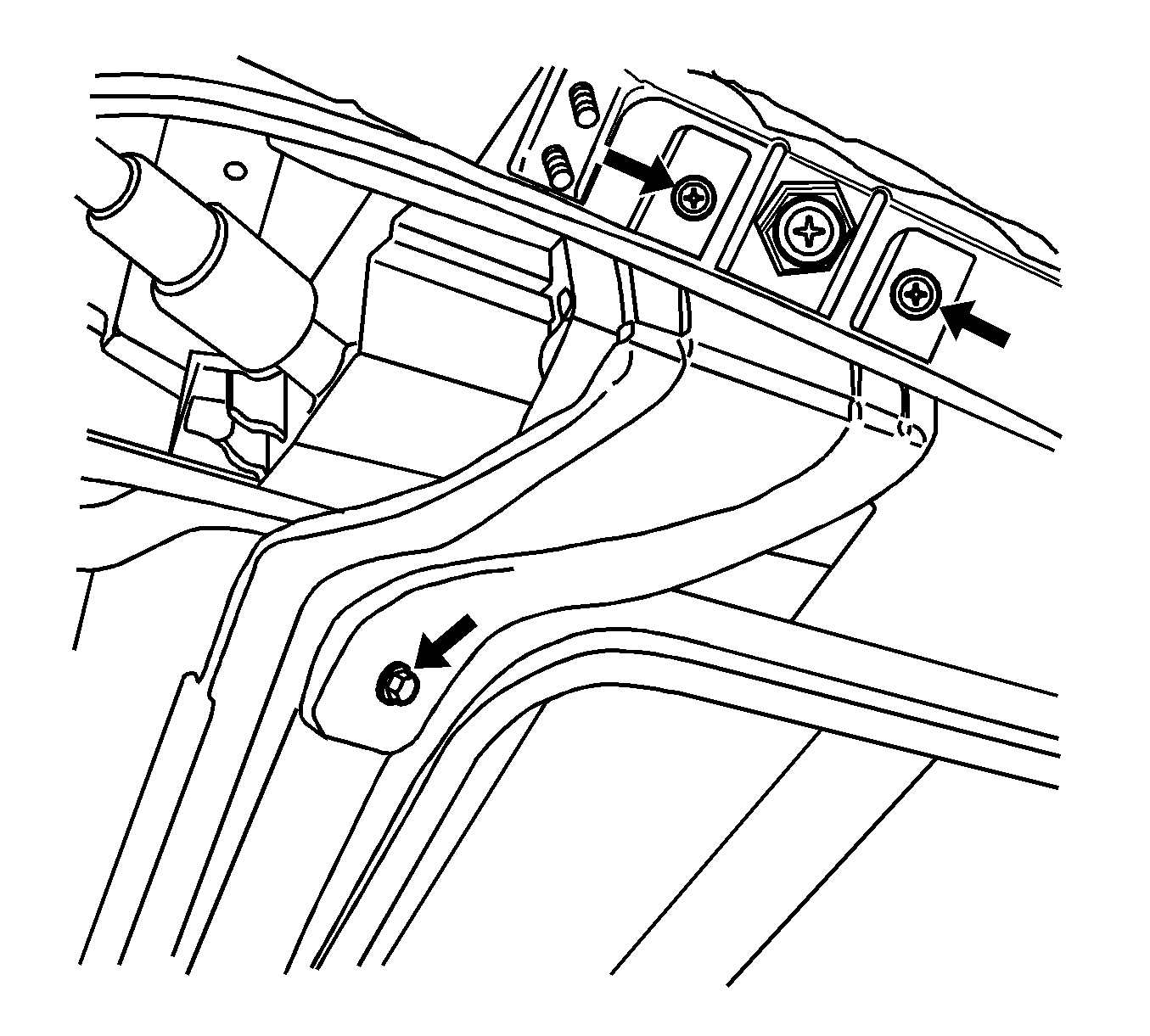
- Install 28 Mylar washers to the mounting bolts/fasteners. Drop the headliner enough to access these attachments, being careful not to bend or damage the headliner while performing the following procedure. Loosen all front 4 module mounting bolts (refer to figure 1). Verify that the screws are not engaged into the roof.
- Install 8 of 28 Mylar washers, two on each of the front four compensators (refer to figure 1 & 2).
- Always retract the barrel (down) to begin reinstallation process.
- Approximate compensator barrel location after tightening during reinstallation process.
- Reinstall the front four compensators per the following procedure. Spin all front four compensator barrels all the way down (refer to figure 3 A, B).
- Install 20 of 28 Mylar washers - four to A, C, A1, C1 (refer to figure 5 & 6). Install two washers to B and B1 between the compensator and the roof (refer to figure 2 & 6). Follow the procedure below.
- Starting with A, remove the TORX screw from the center of the 19 mm nut. Discard the small retaining spring holding the TORX screw to the 19 mm nut. Insert two Mylar washers in between the TORX screw and the 19mm nut and insert two Mylar washers above the 19 mm nut between the height adjuster and the body (refer to figure 5). Complete this procedure for B, C, A1, B1, C1 using the sequence below.
- Lubricate all 10 module compensators/attachments areas with GM Super lube (P/N 12346241 [in Canada use P/N 10953474]) prior to reinstallation of the headliner (refer to figure 7).
- If the vehicle was built before May 9th, 2007, verify that the flock tape is in place on the headliner as described in Condition #10.
- Test drive the vehicle to confirm that all noises have been eliminated.
- Reinstall the headliner.
Figure 1
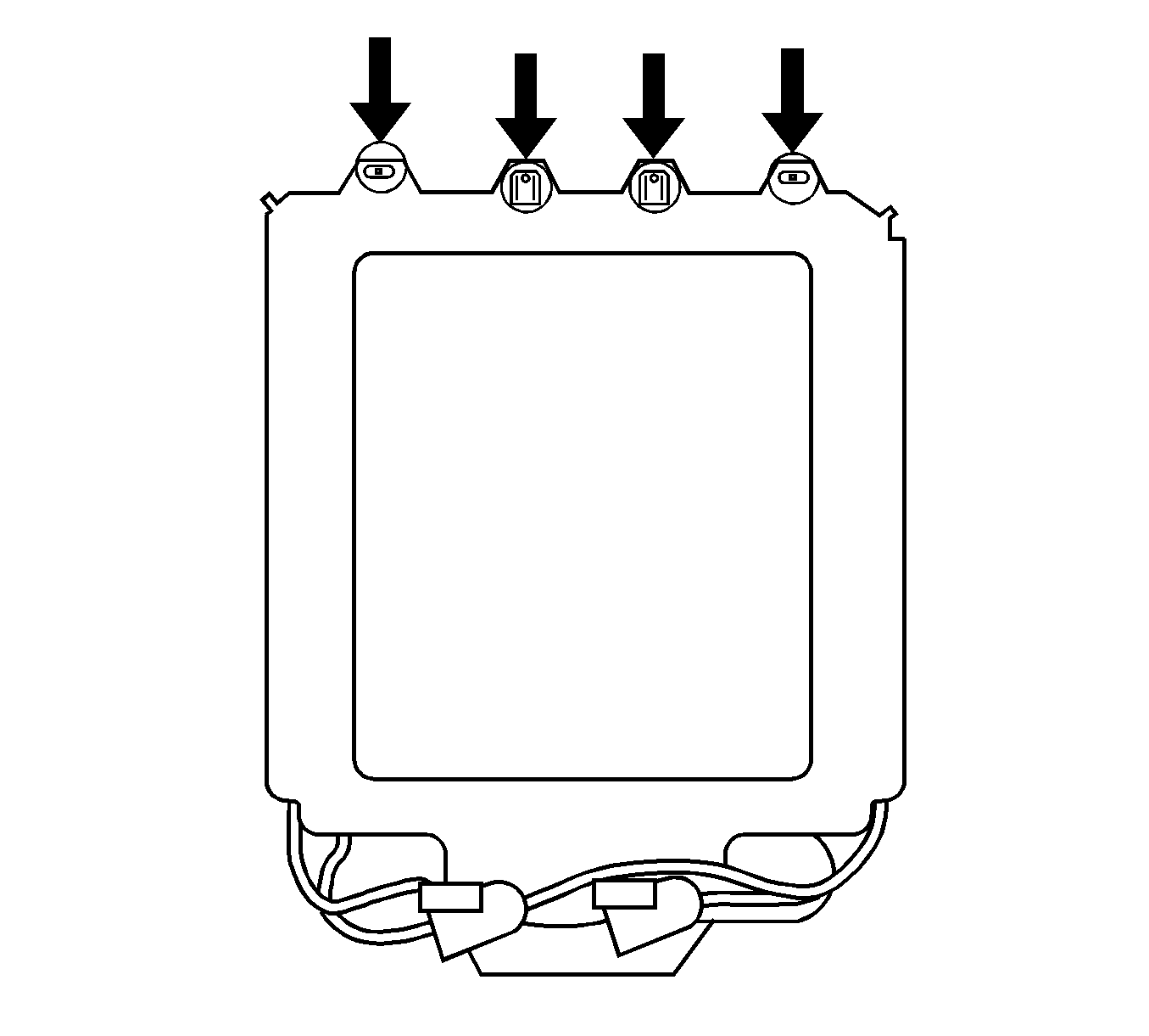
Figure 2
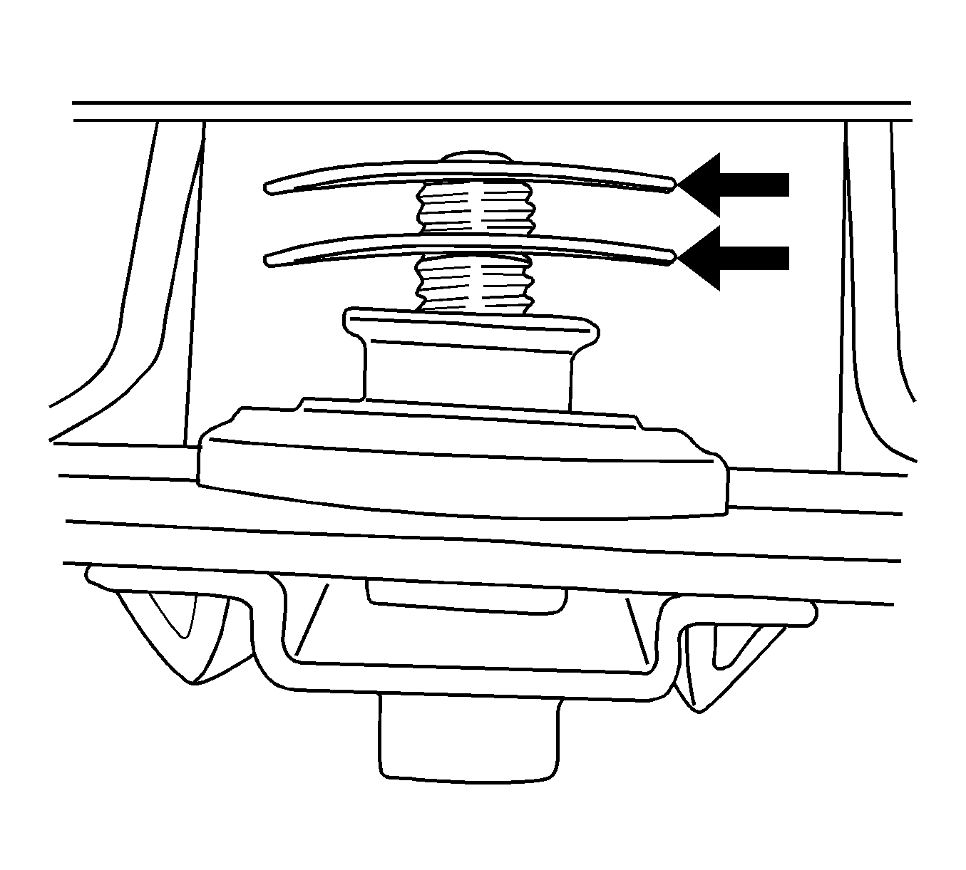
Figure 3A
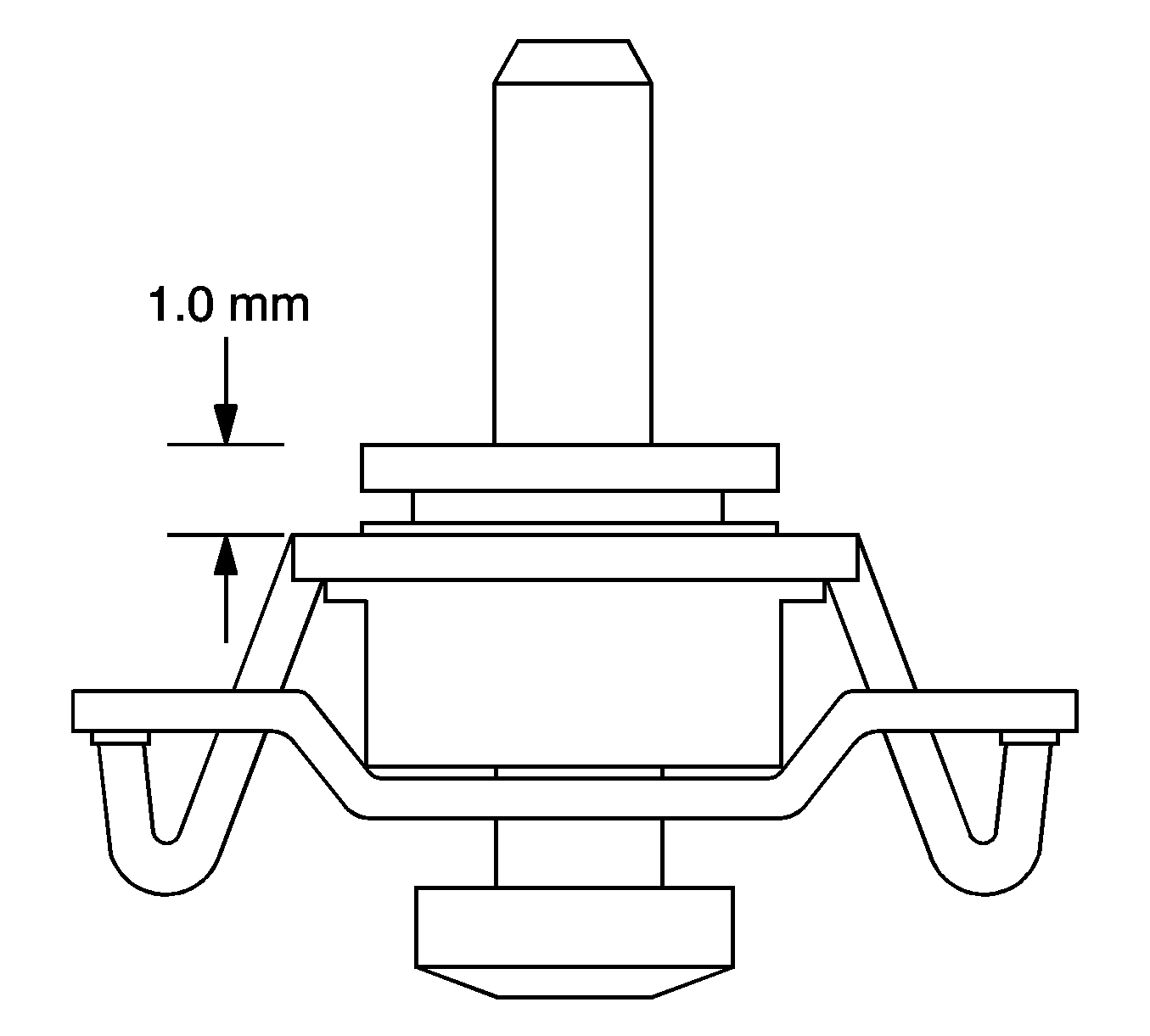
Figure 3B
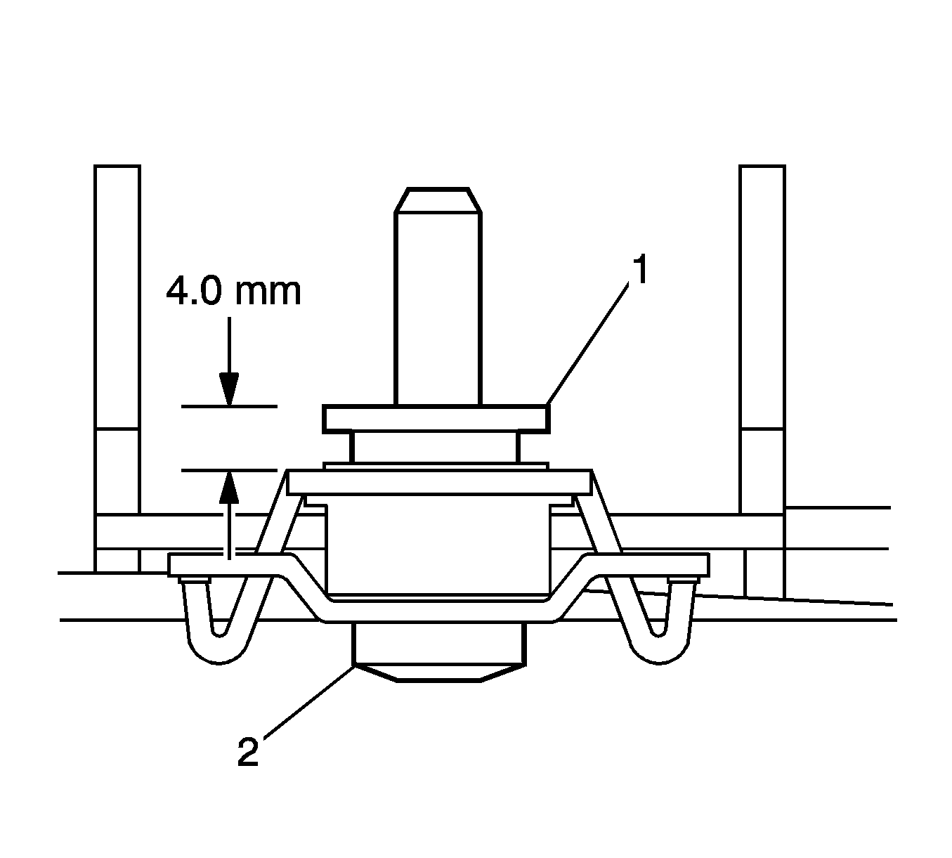
Figure 4A
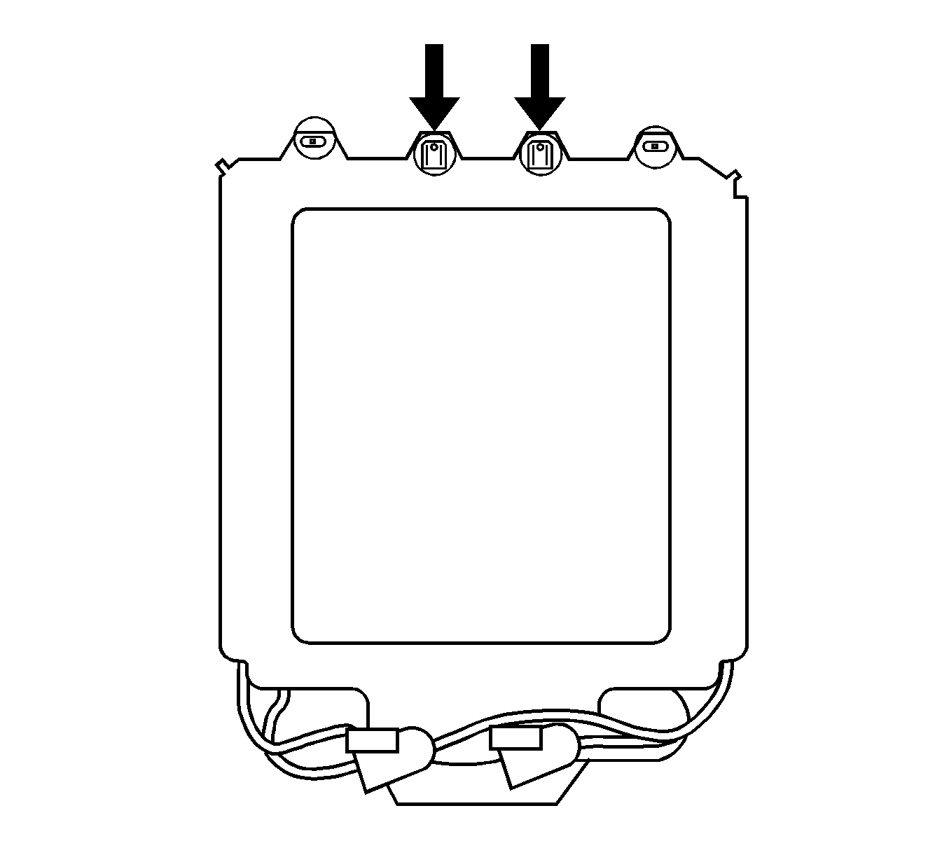
Figure 4B
Important: To achieve proper seal to body compression, have one person push firmly upward on the black rail of the module between the two front center compensators as another person tightens the center two compensators (refer to figure 4A).
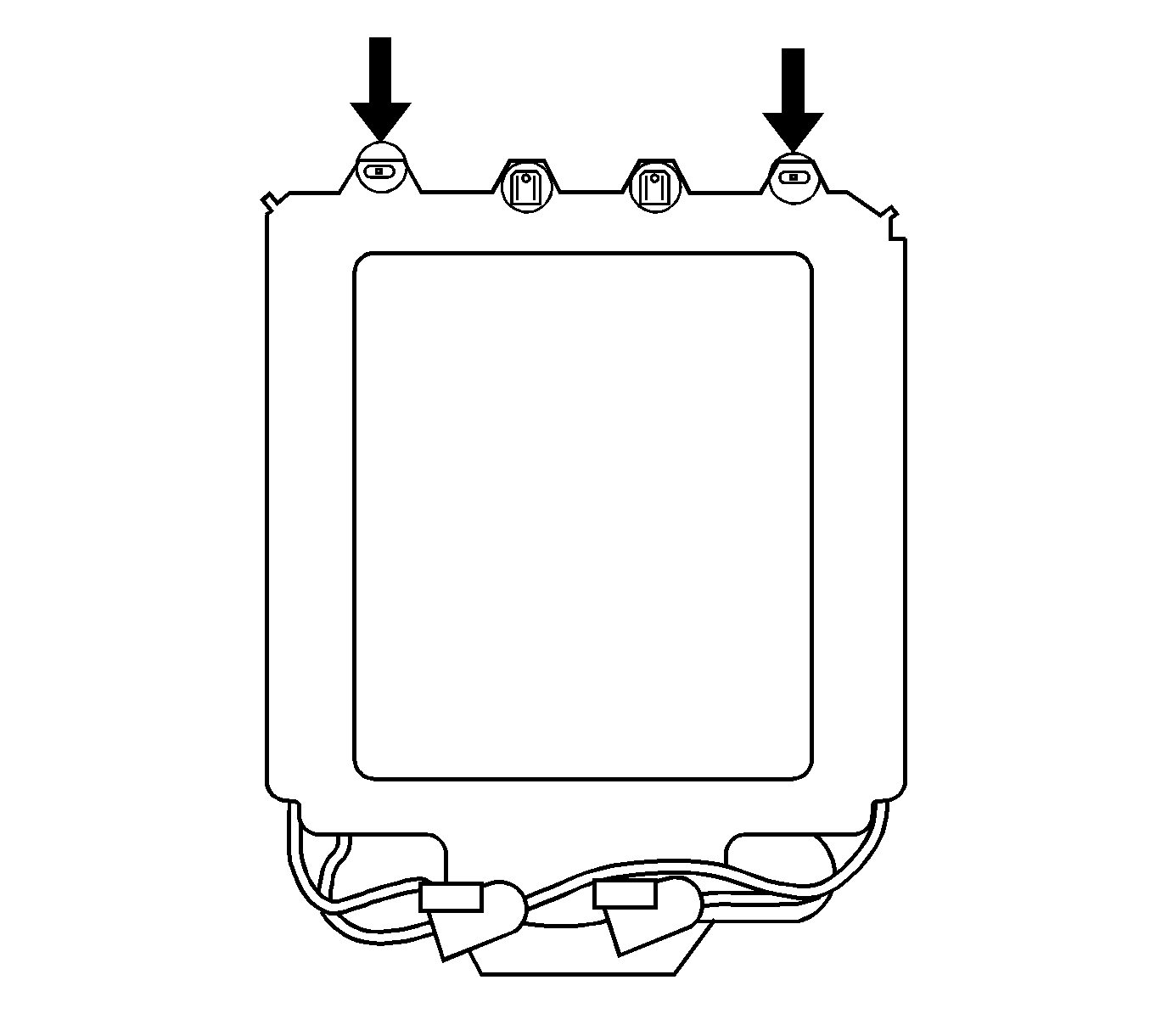
This will improve the seal contact along the front edge of the module to body. Then reinstall the two outboard tolerance compensators to the roof. (Torque specification 10 N·m/89 lb in) (refer to figure 4B)Figure 5
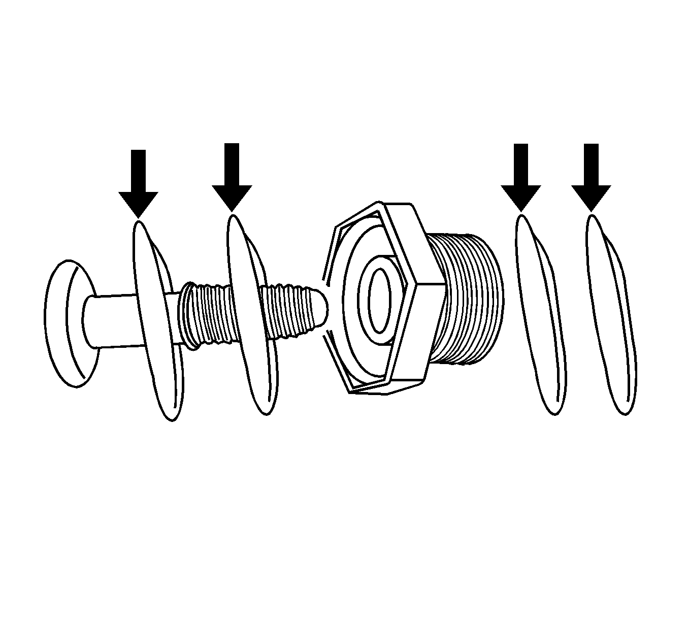
Figure 6
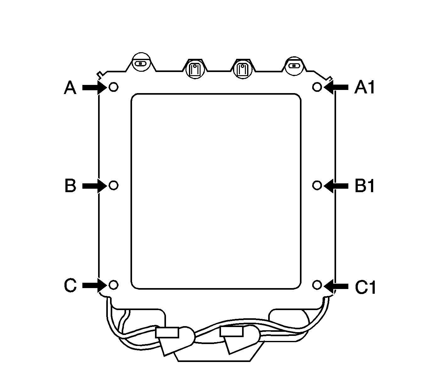
Important: To prevent the sunroof from dropping, loosen one corner at a time following the procedure listed below. Do not over tighten the mounting bolts.
| • | Loosen A. (refer to figure 6 and description above). |
| • | Loosen B. |
| • | Install four washers to A (refer to figure 5) and two to B (refer to figure 2). |
| • | Tighten A. (See note # 1 below) |
| • | Loosen C. |
| • | Install four washers to C. |
| • | Tighten C and B. (See note # 1 and note # 2 below). |
| • | Repeat for A1, B1 and C1. |
| Note # 1: Retighten TORX screw into body to 10 N·m/89 lb in. |
| Note # 2: Prior to fastening the two side center tolerance compensators B and B1 (refer to figure 6), turn the compensator to lower the barrel to its lowest position (refer to figure 3). Before fastening, get out of the vehicle and observe the main seal to body contact. If the seal appears to have good engagement to the roof, proceed with tightening the center two tolerance compensators screws, B and B1 (torque specification 10 N·m/89 lb in). |
| If the seal does not appear to have good engagement to the roof, from the inside of the vehicle, have one person push firmly upward on the center black rail of the module, while the other person tightens the two side center compensators B and B1. This will improve the seal compression to module. |
Figure 7
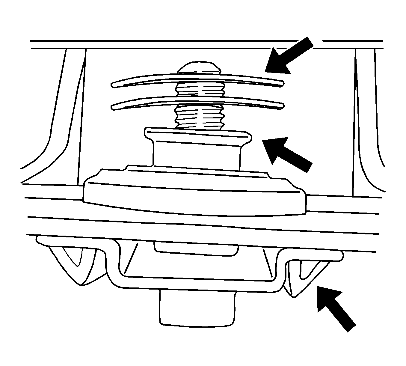
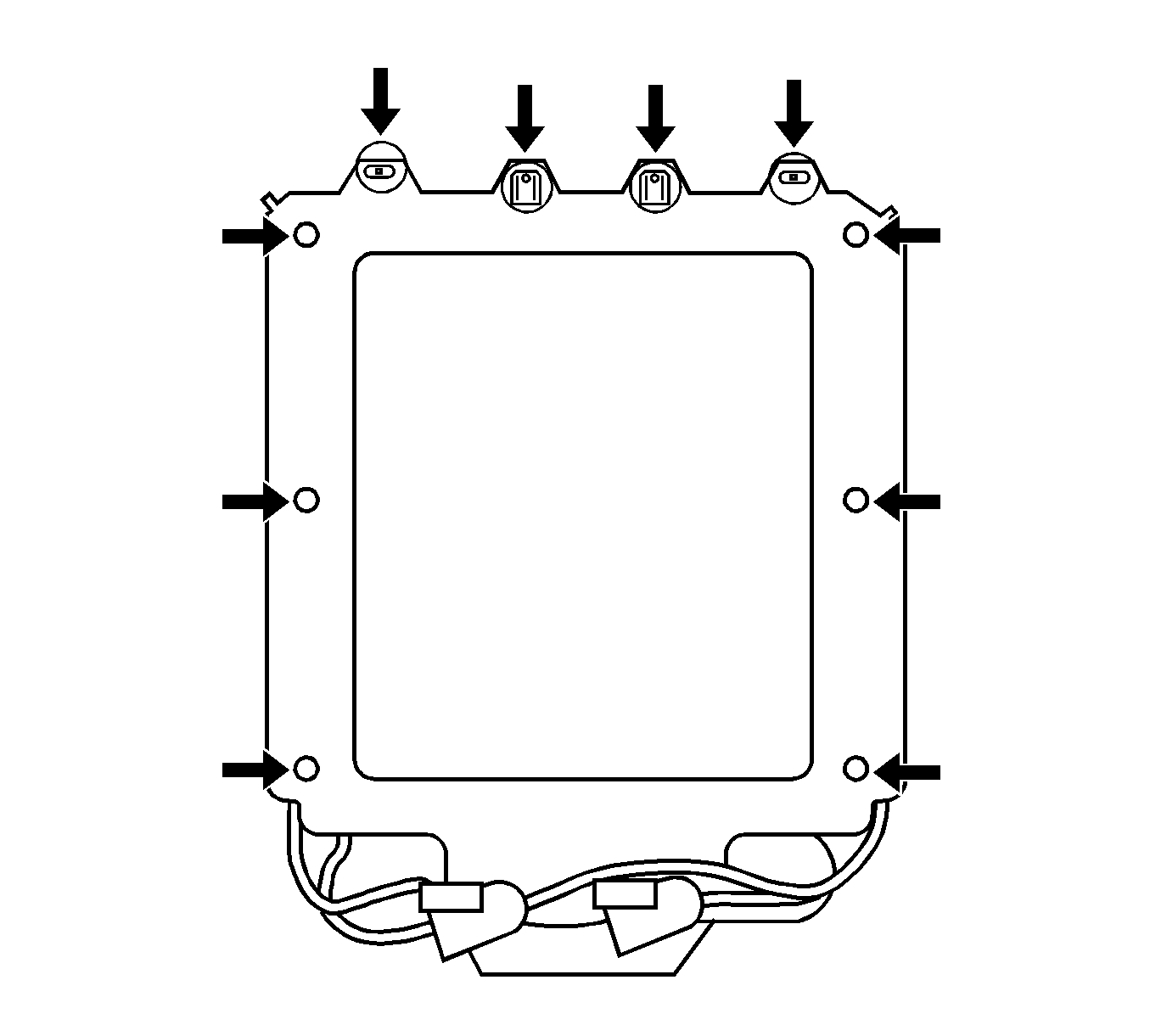
Caution: Be cautious when spraying GM super lube. To avoid any damage to the interior trim, cover all exposed areas before spraying. While spraying, use a shop towel with the other hand to catch any drips and pat the sprayed area to remove any excess lubricant.
Condition #2
Some customers may comment on wind noise coming from the glass panel areas of the sunroof. This condition could also be reported as a HVAC blower motor whistle type noise that changes with HVAC blower fan speed.
Cause
This condition may be caused by one of more glass panels out of adjustment and not sealing properly.
Correction
VERIFY THE CUSTOMER CONCERN - Windnoise and/or HVAC blower/whistle type noise can vary depending on the blower fan speed setting. Higher fan speeds increase cabin pressure allowing more air flow out of the cabin through marginal sealing areas. To properly diagnose, it is important to know at what vehicle speeds and/or what fan speed settings the windnoise occurs. Another diagnostic method to detect panel to panel air leakage, while the vehicle is sitting in the service stall, is by tracing the perimeter of each glass panel with the open hose end portion of a stethoscope-type tool with all the vehicle doors and windows closed and the HVAC blower speed on high.
- Install cross car foam to the first three glass panels of the module. The cross car foam is installed on the extruded glass reinforcement in the channel area (back of the glass panel on the inside). This is best done when the sunroof is open all the way. To install cross car foam, clean the extruded glass reinforcement channel with alcohol. Install the cross car foam in the channel area, centered from one end to the other on the first glass panel (refer to figure 8). Figure 8 shows the underside of the 1st panel with the foam strip added to the extruded glass reinforcement. This foam acts as a sound deadener
- Repeat the same for Panels 2 and 3.
Figure 8
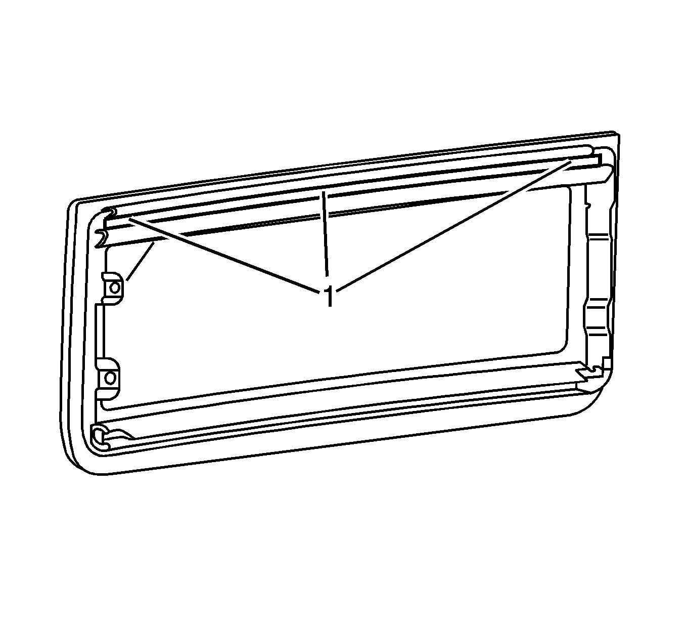
Important: The foam should be seated evenly in the channel and across the panel to ensure proper glass panel sealing.
Test drive the vehicle, and ONLY if the noise is still present perform the following taping diagnostic procedure to determine the source of leak and proper glass panel adjustment.
| • | Run a line of tape across the vehicle from module seal to front of first glass panel (refer to figure 9). Test drive. If the noise is gone, adjust the first glass panel downward to create a better seal per the procedure below. |
Figure 9
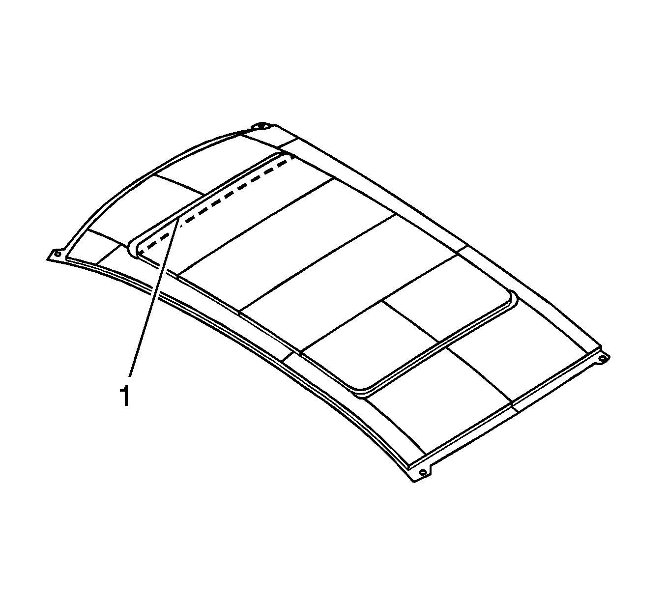
| • | If the noise is still present, run a line of tape across the vehicle covering the back of the first glass to the front of second glass. If the noise is gone, adjust the second glass panel downward to create a better seal. |
| • | If the noise is still present, run a line of tape across the vehicle covering the back of the second glass to the front of third glass. If the noise is gone, adjust the third glass panel downward to create a better seal. |
| • | If the noise is still present, run a line of tape across the vehicle covering the back of the third glass to the front of fourth glass. If the noise is gone, adjust the fourth glass panel downward to create a better seal. |
Glass Panel Adjustment Procedure
Adjust the glass panel downward one side at a time.
- Remove side actuator covers. Use care when lifting up on the corners of the sunroof window actuator side cover to expose the screws. Use care not to break off the end tabs.
- With the sunroof panels closed, loosen both actuator screws on the side of the glass panel to be adjusted (refer to figure 10).
- Have someone from outside the vehicle lightly apply pressure downward on the center outer edge of the glass while the other person tightens the actuator screws on that side of the glass.
- Test drive the vehicle to verify windnoise is eliminated. If not, repeat Steps 1 through 4 for the other side of the glass and/or for the other glass panels as necessary.
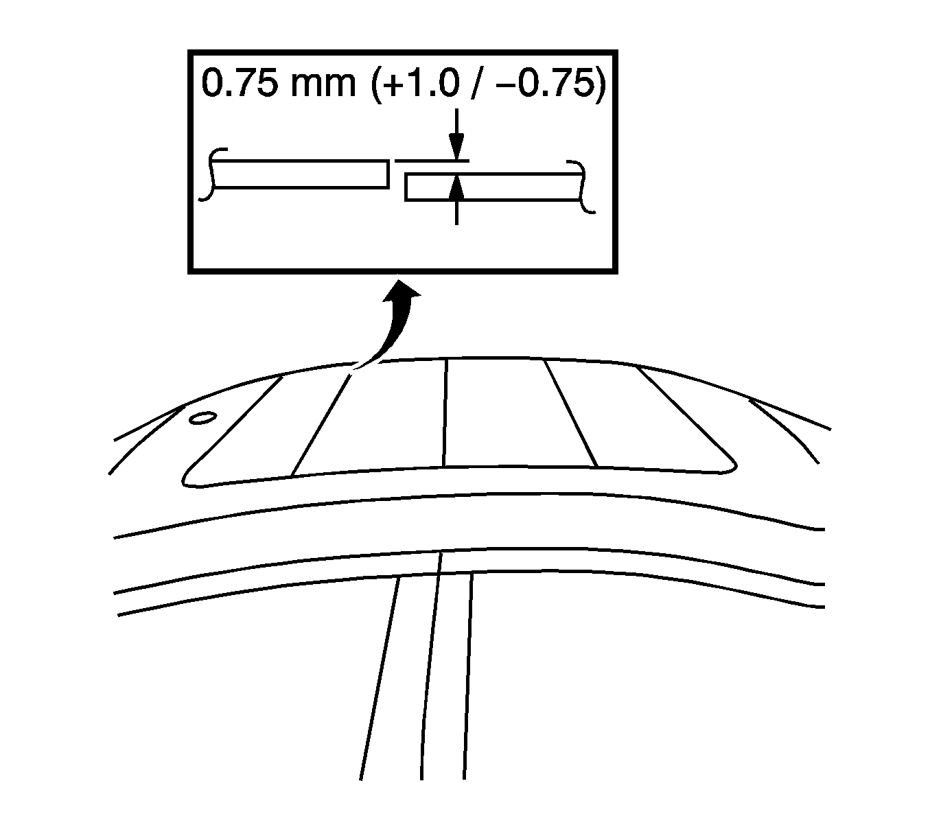
- Cycle the roof to the full open and back to its closed position. Verify the glass panels are within the measurement specifications (refer to figures 11 & 12).
Notice: The first glass panel must be open to remove the actuator side covers; all others can be removed closed.
Figure 10
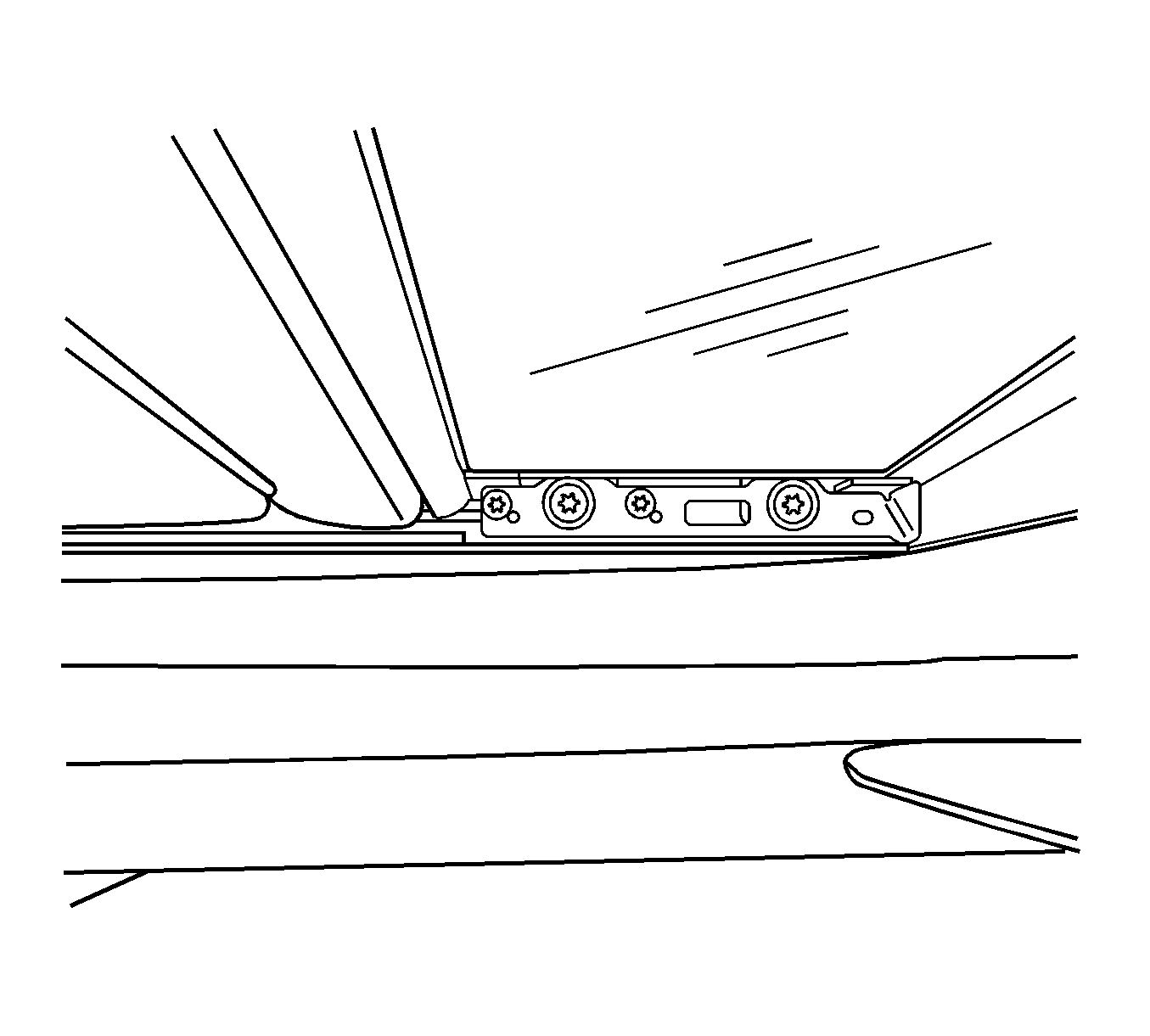
Notice: Over compression of the seal may cause too much resistance on the seal to glass interface potentially causing false reversals when attempting to close sunroof.
Figure 11
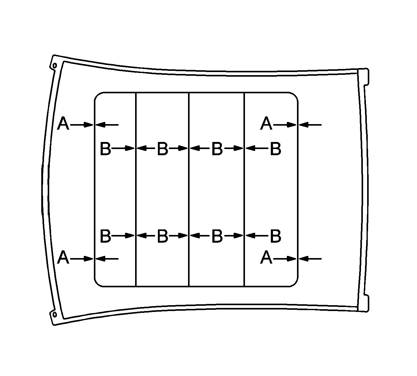
Figure 12
A = Gap between glass edge to metal roof edge. Panoramic Roof (Gap) 4.0+/- 1.5 mm (front). Panoramic Roof (Gap) 4.0 +/- 1.5 mm (Rear)
B = Gap between glass panels. 4.0 mm +/- 1.5 mm Glass gap between 1st & 2nd, 2nd & 3rd and 3rd & 4th panels.
Important: It is always desirable to have glass panels display a slight shingle effect (refer to figure 12).
Figure 13
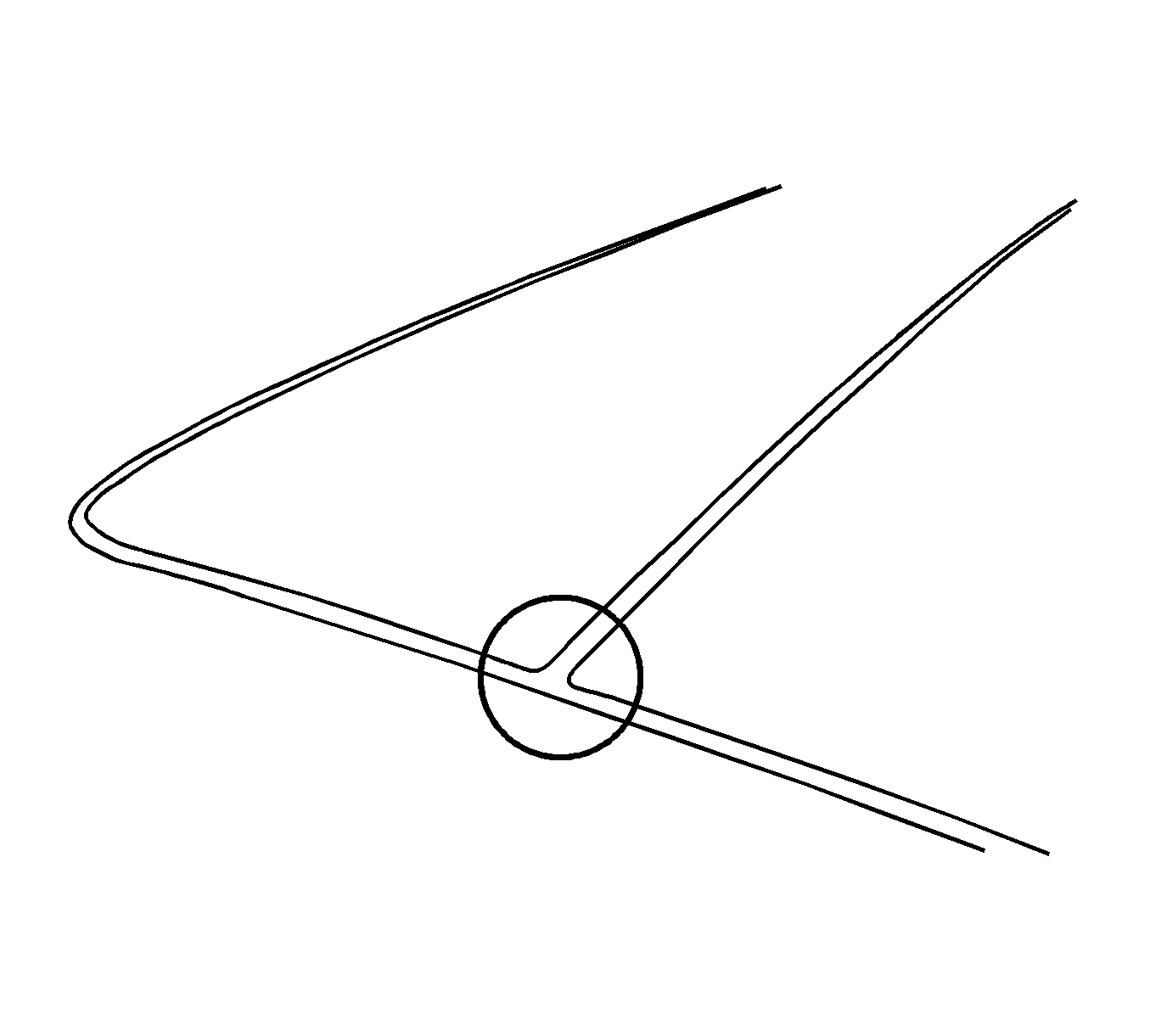
Important: Keep in mind that some air leakage is normal at the T-joint areas and are there by design (refer to figure 13).
Condition #3
Some customers may comment on wind noise/wind rush type noise coming from outside of the vehicle in the sunroof module seal to roof area.
Cause #A
This condition may be caused by a lack of seal compression from the sunroof module to metal roof.
Cause #B
A rolled seal and/or a puckered seal at one of the corners at the module.
Cause #C
Correction A and Cause B do not correct the windnoise.
Correction A
Lack of Module Seal Compression to the metal roof
- Verify the noise condition, visually inspect the entire perimeter of the module seal for improper/uneven seal compression and/or gaps to the metal roof.
- Using masking tape, tape across the suspected poor sealing area from the roof metal to the seal. Test drive and verify the noise is gone. If the noise is gone follow the appropriate procedure below. If the noise is still present, repeat steps 1 and 2 as required.
- Verify the front of first glass is flush to -1 mm below the roof (refer to figure 12). If the front of 1st glass is higher than the roof, readjust the front of first glass using the procedure described in the Glass Panel Adjustment Procedure (Condition #2).
Figure 14
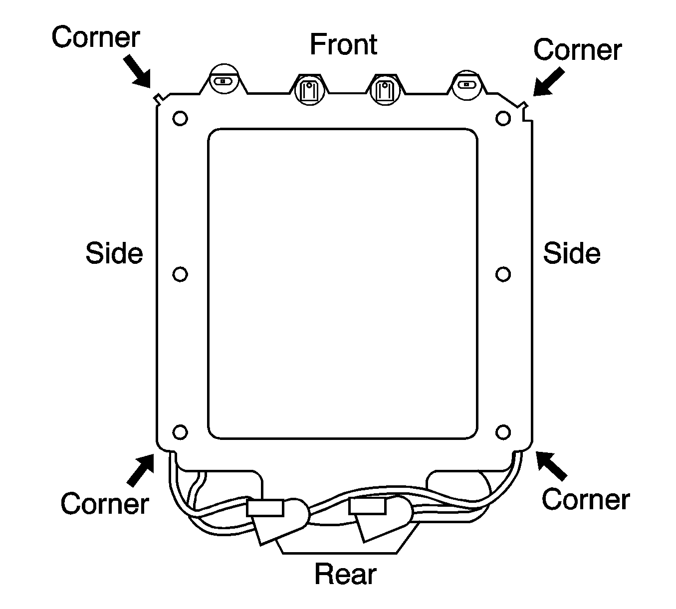
| • | If the noise is coming from the front center of the sunroof module (refer to figure 14), loosen all front 4 module mounting bolts (refer to figure 1). Verify that the compensators are not engaged into the roof. Spin all front four compensator barrels all the way down (refer to figure 3). |
| Important: To achieve proper seal to body compression, have one person push firmly upward on the black rail of the module between the two front center screws as another person tightens the center two screws (refer to figure 4). This will improve the seal contact along the front edge of the module to body. Then reinstall the two outboard tolerance compensators to the roof. (Torque specification 10 N·m/89 lb in) (refer to figure 4A). |
Figure 15
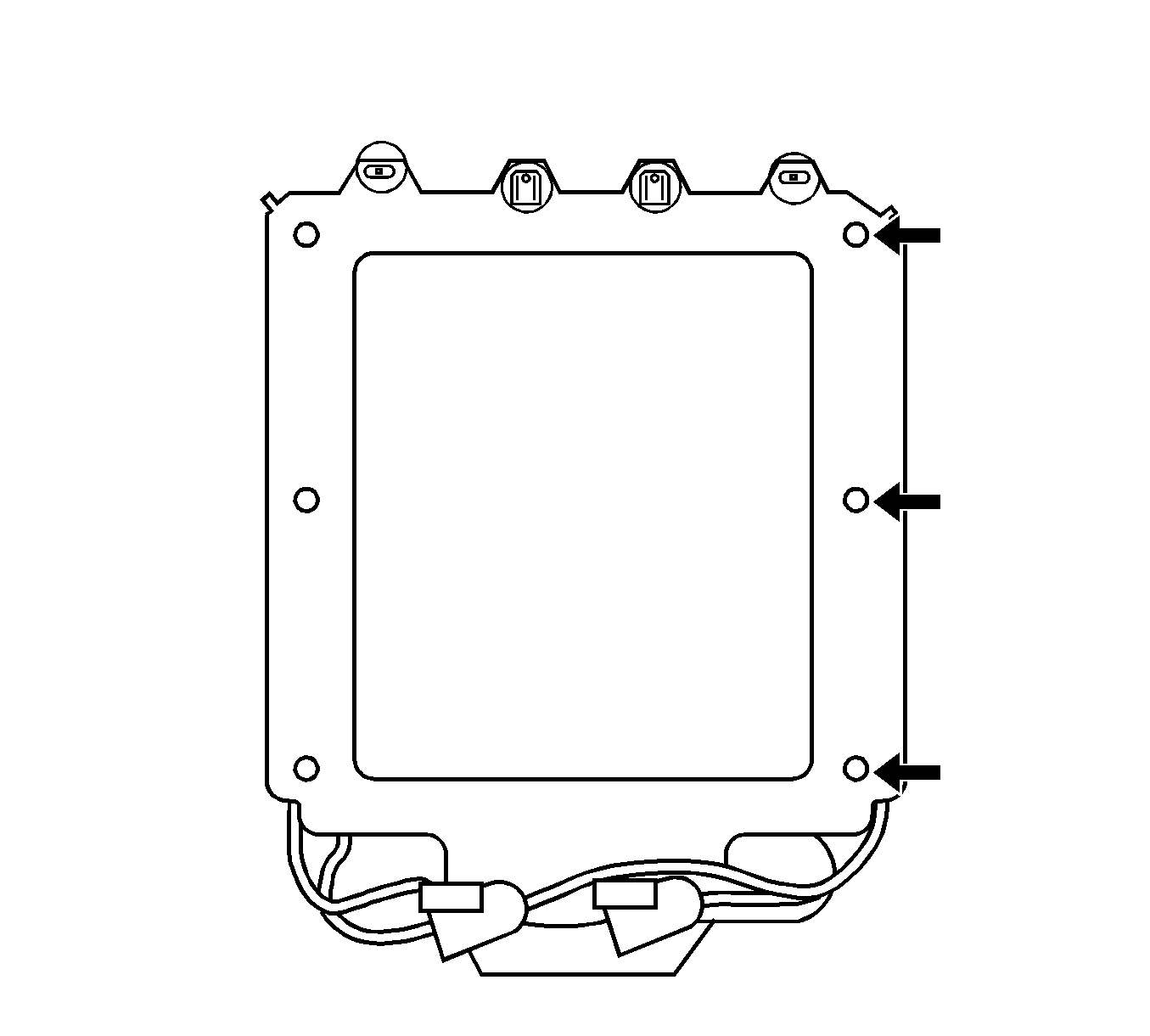
| • | If the noise is coming from the side center of the sunroof module (refer to figure 14), loosen the three side mounting bolts (refer to figure 15). Verify that the compensators are not engaged into the roof. Spin all the three compensator barrels all the way down (refer to figure 3). |
| Important: To achieve proper seal to body compression, have one person push firmly upward on the center of the side black rail of the module as another person tightens the center compensator (refer to figure 15). This will improve the seal contact along the side center edge of the module to body. Then reinstall the other two side outboard tolerance compensators to the roof. (Torque specification 10 N·m/89 lb in). |
Figure 16
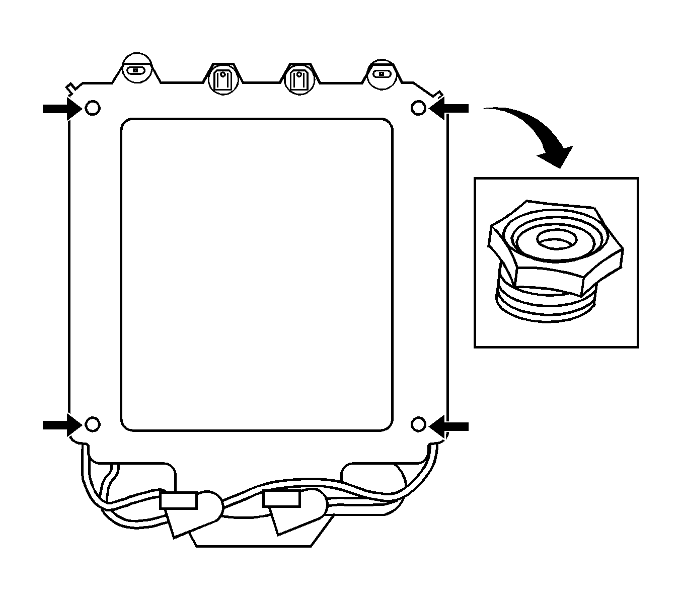
| • | If the noise is coming from the one of the four corners (refer to figure 14), adjust the proper corner leveling nut (height adjusters) accordingly (19 mm hex heads) (refer to figure 16). |
| Important: When you loosen the nut, you are tightening the seal to roof, creating a better module to roof seal. When you are tightening the nut, you are loosening the seal to roof. |
Condition B
Verify seal fit consistency to the entire perimeter of the roof.
Repair rolled perimeter seal by spooning into position with "Trim Stick" or credit card type tool.
Figure 17
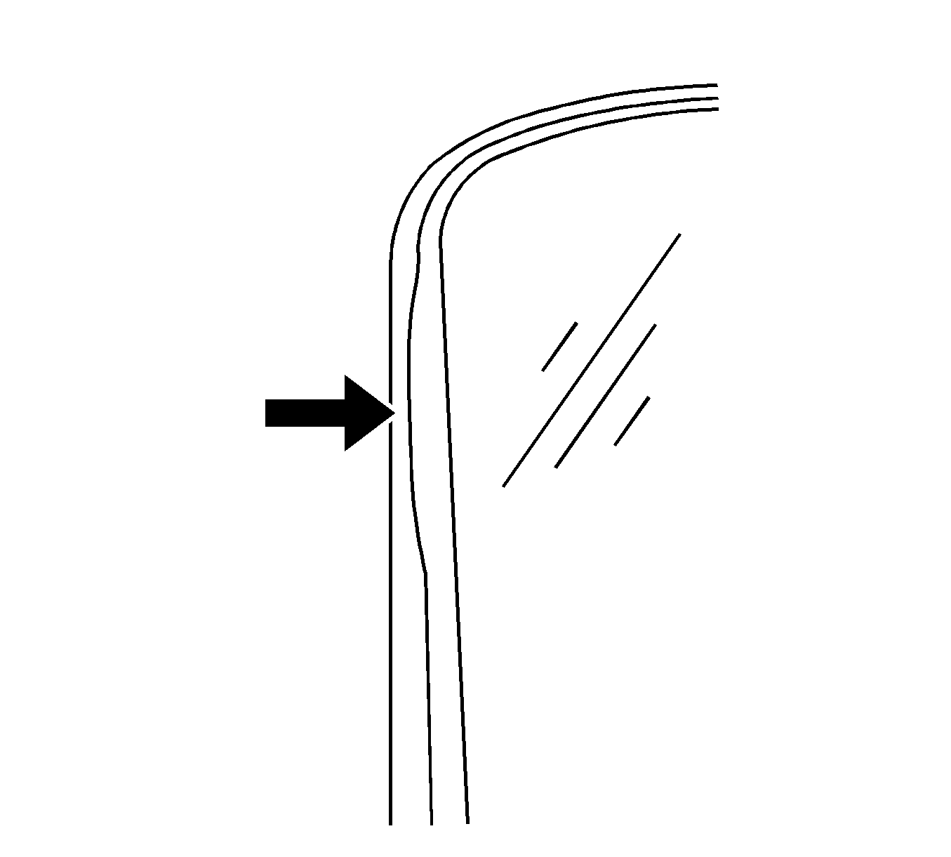
Incorrect position rolled seal.
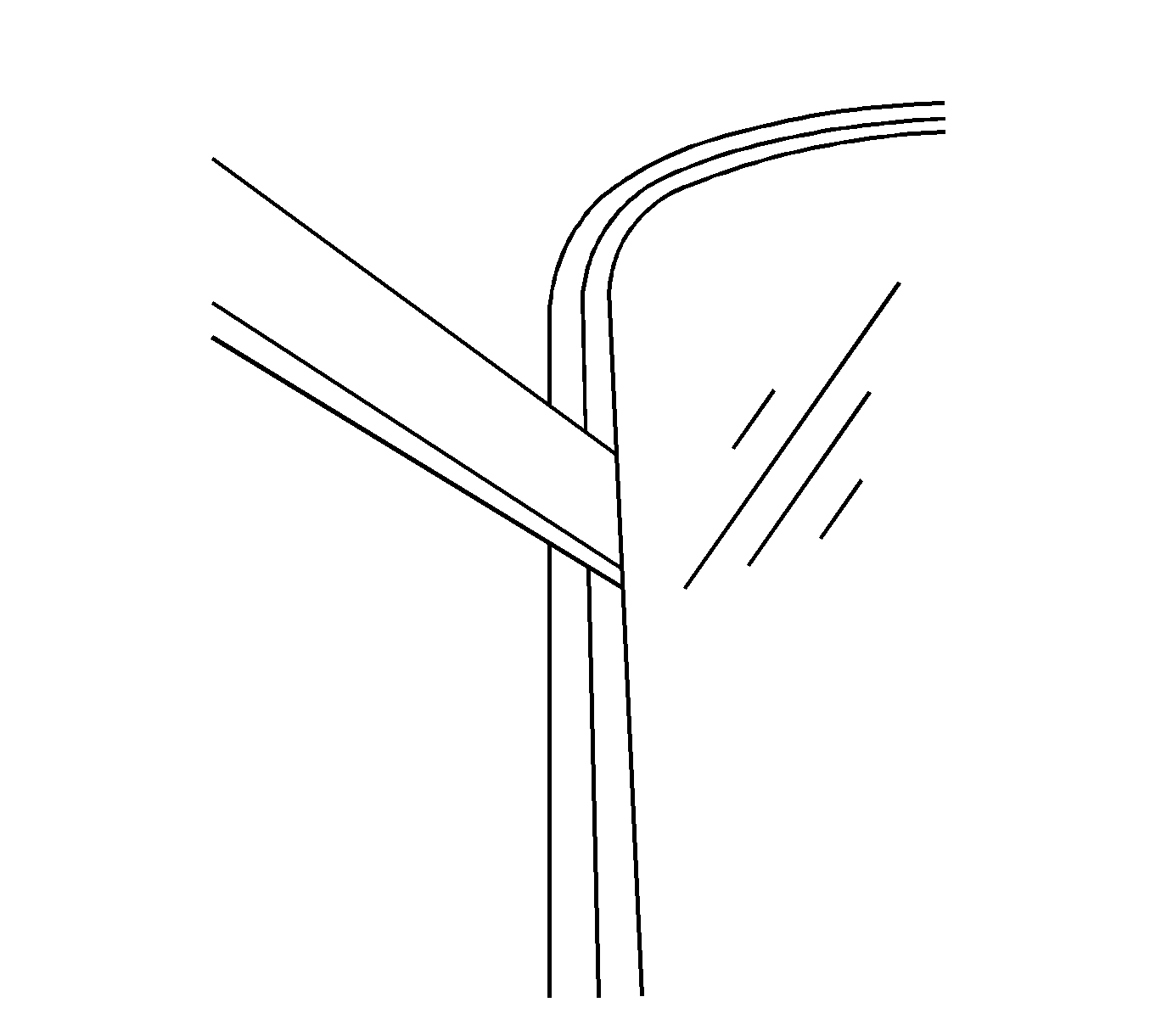
Pull seal out from under roof edge with trim stick.
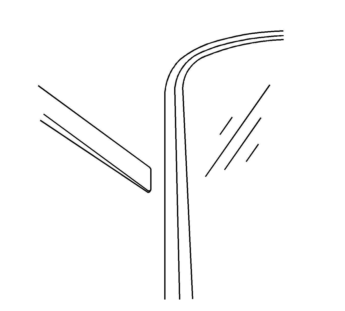
Corrected position.
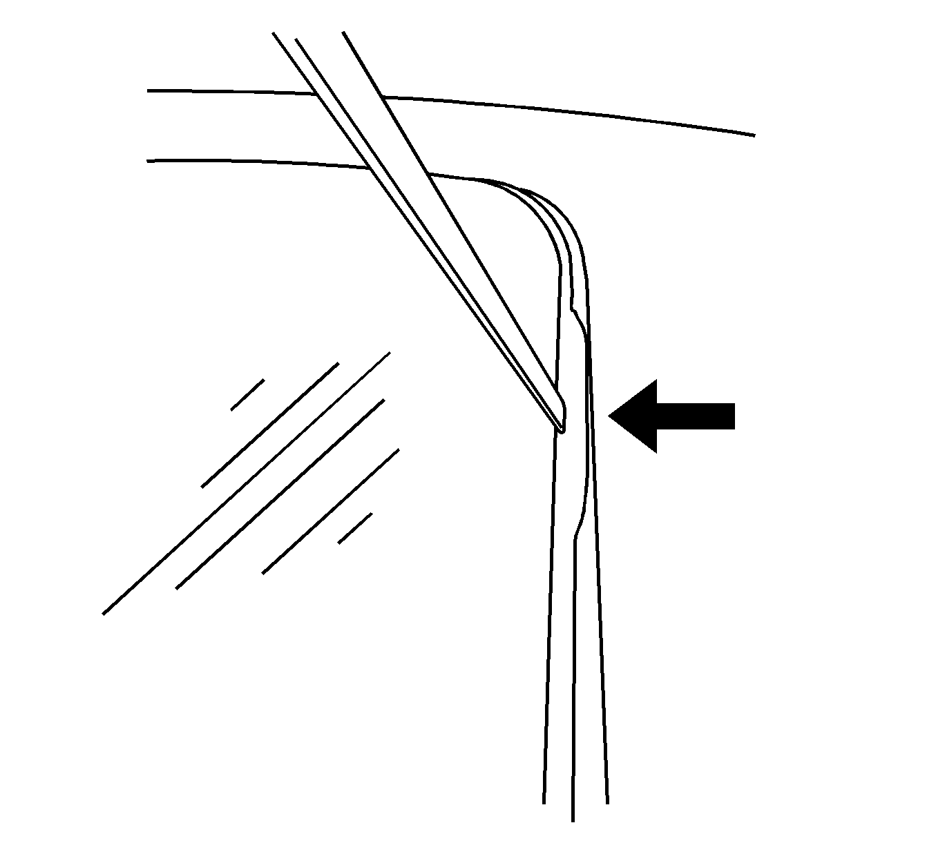
Push seal back under roof edge with trim stick.
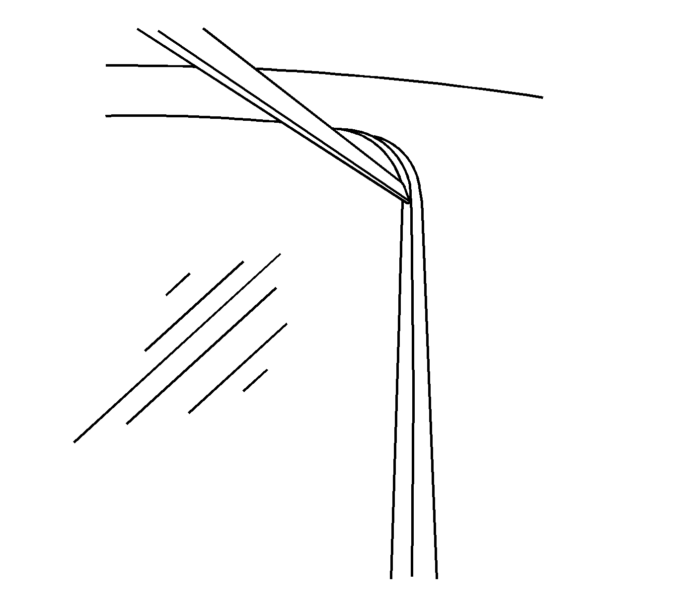
Corrected position.
Important: Test drive vehicle and verify condition is gone.
Notice: In some instances, over longer periods of time and sun exposure, the seal may take a permanent set. In these types of cases, the seal may have to be replaced (see Correction C below).
Correction C
Replace the sunroof module seal.
DO NOT order an entire sunroof module to get the seal. Note: the new seal can be obtained by calling the Warranty Parts Center.
If Correction A & B don't correct the condition replace the seal with P/N 25866123 and adjust the front glass panel properly (refer to Sun Roof Window Alignment in SI).
Important: When installing the new seal, DO NOT remove all glass panels. Remove only the first and last glass panels, with the sunroof in the open position, remove the old seal and install the new seal working your way around the perimeter of the roof. This will avoid the need to totally readjust all four glass panels. Use the ignition key to properly place the panel in the appropriate position to properly install and seat the seal.
After installing the module seal, reinstall and properly adjust first and last glass panels. Operate the sunroof to ensure proper operation. Test drive vehicle to make sure no noise issues are present.
Condition #4
Some customers may comment on glass panel rattling or loose.
Cause
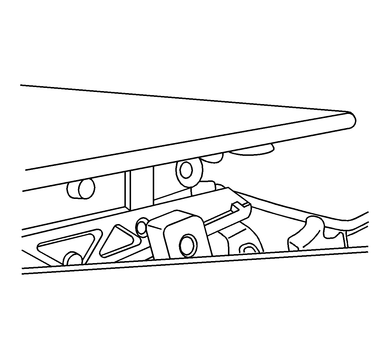
Glass panel retention pins loose or missing.
Correction
DO NOT order an entire sunroof module to get the retention pins. The pins are available through the Warranty Parts Center. Request P/N 401 (2 pins per order).
Figure 18
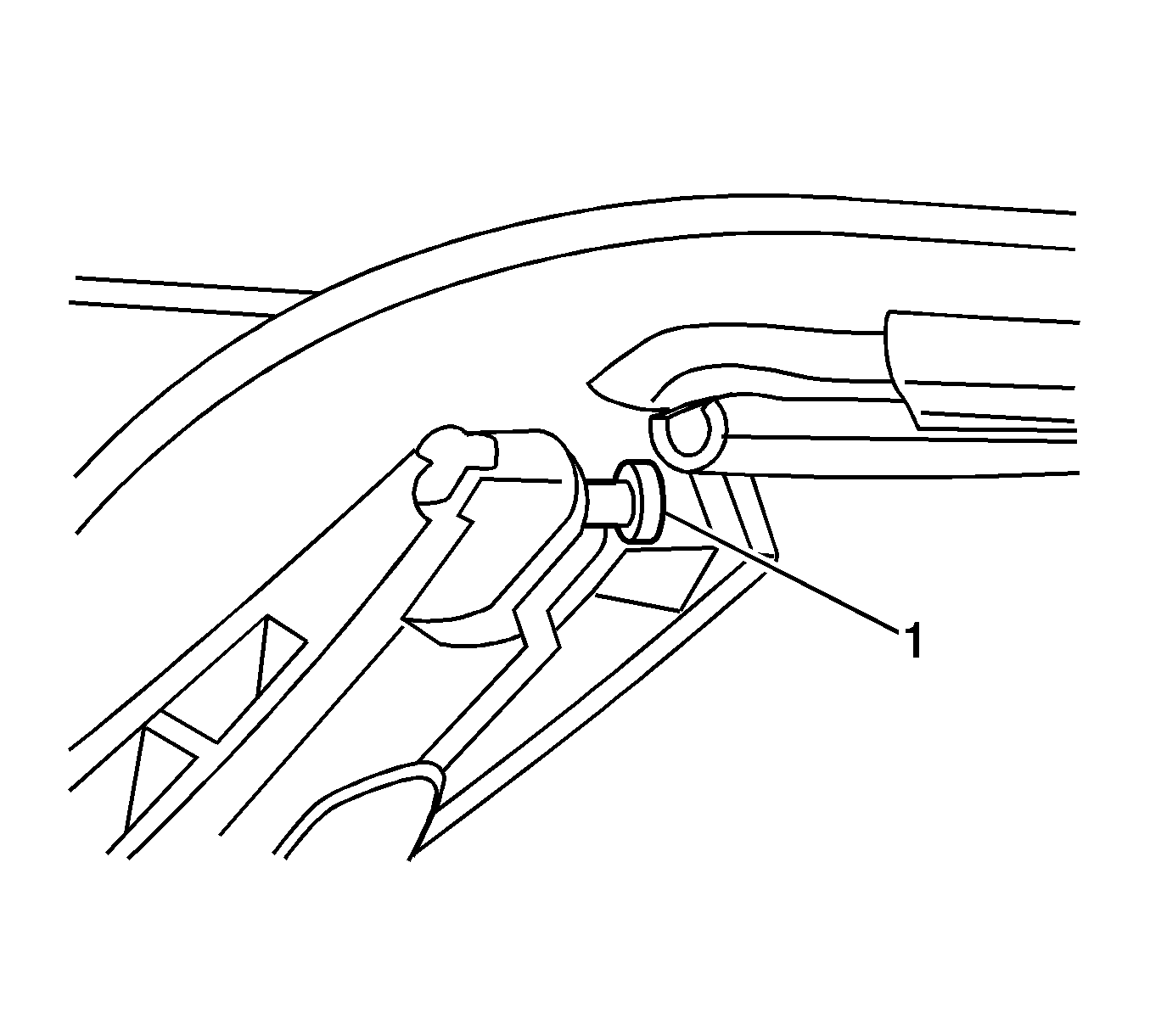
Figure 19
Condition #5
Customers may comment on a plastic/metal rattle type noise that occurs while driving over bumps. This noise usually comes from the rear of the sunroof module.
Cause
This condition may be caused by loose mounting bolts/fasteners.
Correction
Figure 20
Important: Do not over tighten the mounting bolts.
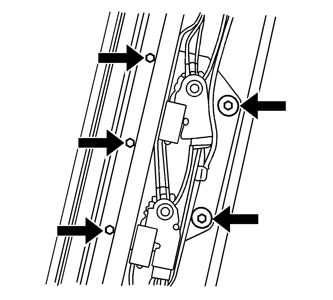
- Partially lower the headliner enough to access these attachments, being careful not to bend or damage the headliner while performing the following procedure. Loosen all (5) rear center mounting bolts and then re-tighten all (5) center mounting bolts at the rear of the module to 10 N·m (89 lb in). Note that the forward 3 mounting bolts are accessed by the holes in the sunshade when the sunshade is fully closed (refer to figure 20).
- Tighten both rear motor attachment screws (3 per motor/6 total) to 4 N·m (35 lb in). (refer to figure 21)
- Press the reinforcement upward while tightening the rear crossmember attachment screws (3 per side/6 total) to 4 N·m (35 lb in) (refer to figure 22).
- Test drive the vehicle to verify condition is gone.
- Re-install the headliner.
Important: These screws should be snug. Do not over tighten the mounting bolts.
Figure 21
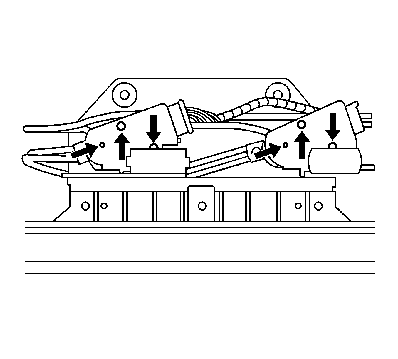
Figure 22
Condition #6
After servicing the sunroof module, the sunshade does not cycle.
Cause
This condition may be caused by an incorrect drive motor on the sunshade.
Correction
Figure 23
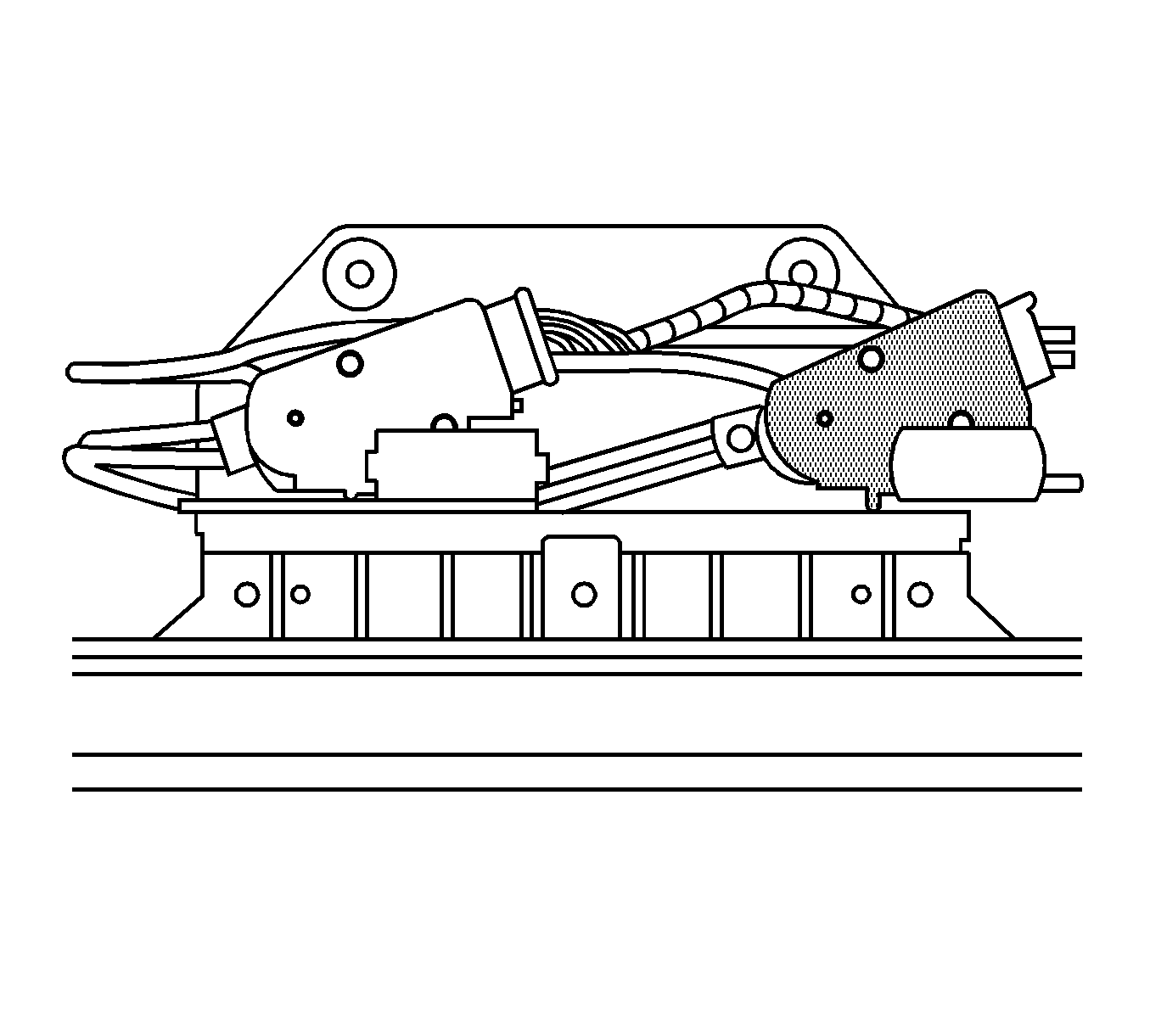
Since both these motor have different internal software, verify that the sunshade motor (passenger side motor) has a black case. (The white case motor is the glass drive motor [driver side motor]) (refer to figure 23).
Condition #7
Seal itch between glass panels.
Correction
Apply GM Weatherstrip Lubricant, P/N 3634770 (in Canada, P/N 10953518), to the entire module seal and at forward seal edge of glass panel 2, 3, & 4. Follow these steps:
- Clean seal areas with a clean shop towel
- Apply lubricant
- Thoroughly work lubrication into seals with clean dry towel so that no excess lube is visible.
Notice: Excess lubrication will attract debris and cause other issues.
Condition #8
Customer complains that intermittently, while closing the sunroof, it reverses and opens.
Cause
Unintended reversals may occur due to high electrical load on the vehicle while operating the sunroof. This could be caused by of one of the following:
- Operation of front windows while closing the roof may result in a unintended false reversal- this is a normal condition and no repairs should be attempted.
- While closing the roof glass panels and turning on the Rear Window Defogger a unintended reversal may occur- this is a normal condition and no repairs should be attempted.
- Contamination / debris in the panoramic tracks may result in a unintended reversal. This is a normal maintenance issue. Tracks should be cleaned and lubed periodically of debris.
Condition #9
Customer may comment on light coming through the T-joints areas.
Cause
It is important to note that this is caused by a clear area in the glass black out for the GM Glass part number. This is a normal condition and is not actual opening in the glass.
Correction
Figure 24
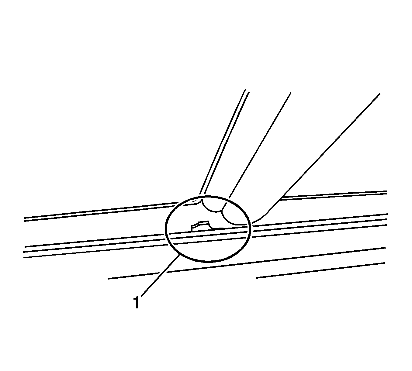
If the customer does not accept this explanation, use a black permanent marker to "black-out" the area (refer to figure 24).
Condition #10
Some customers may comment on an itch type noise occurring over bumps. The noise comes from the front area of headliner at the corners where headliner meets the sunroof module, over the driver’s and/or front passenger’s head area.
Cause
Figure 25
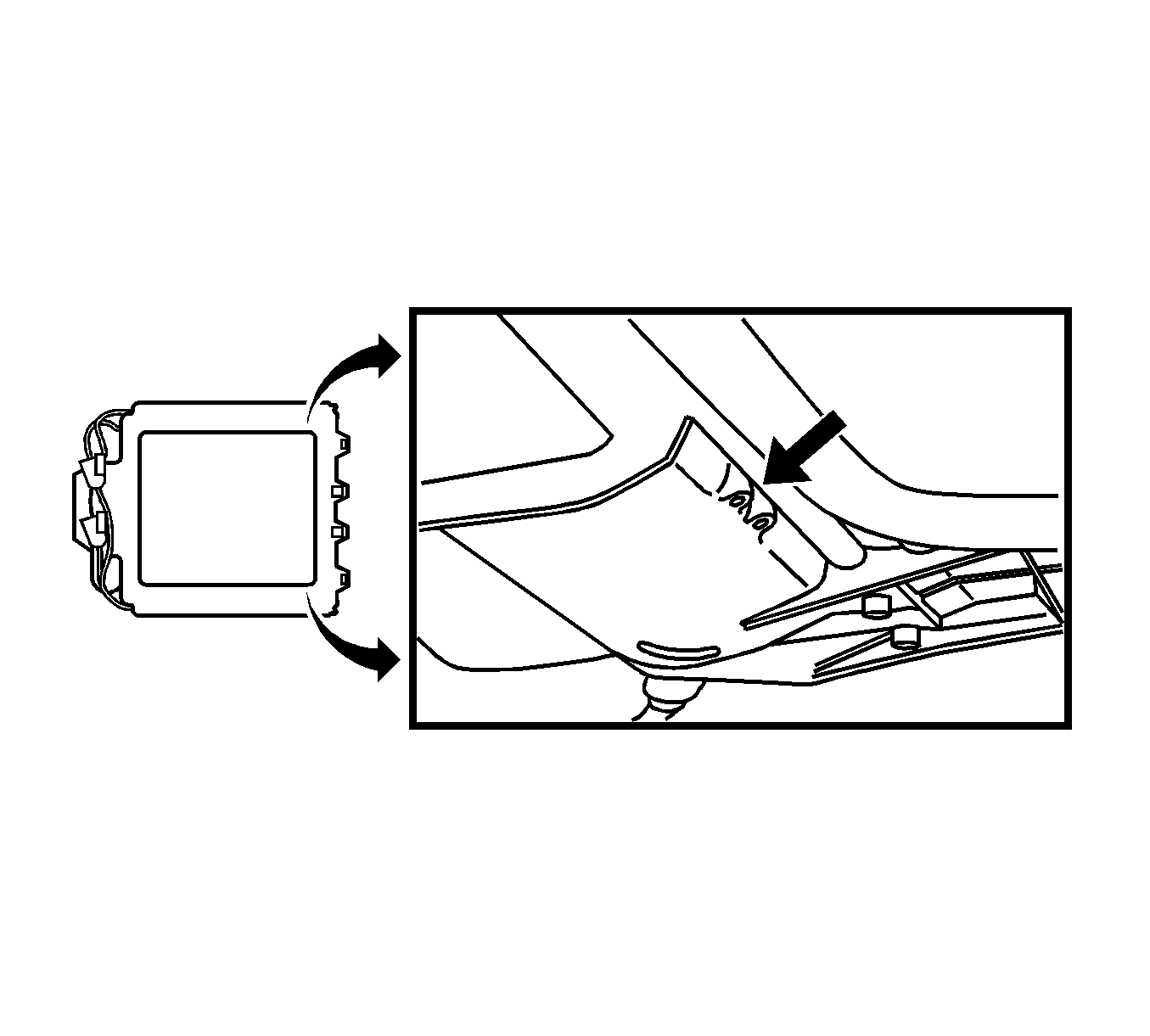
The headliner may rub on a pair of plastic screw boss holes (empty/no screws in these bosses) that are part of the sunroof module on each side of the module towards the front (refer to figure 25).
Correction
Figure 26
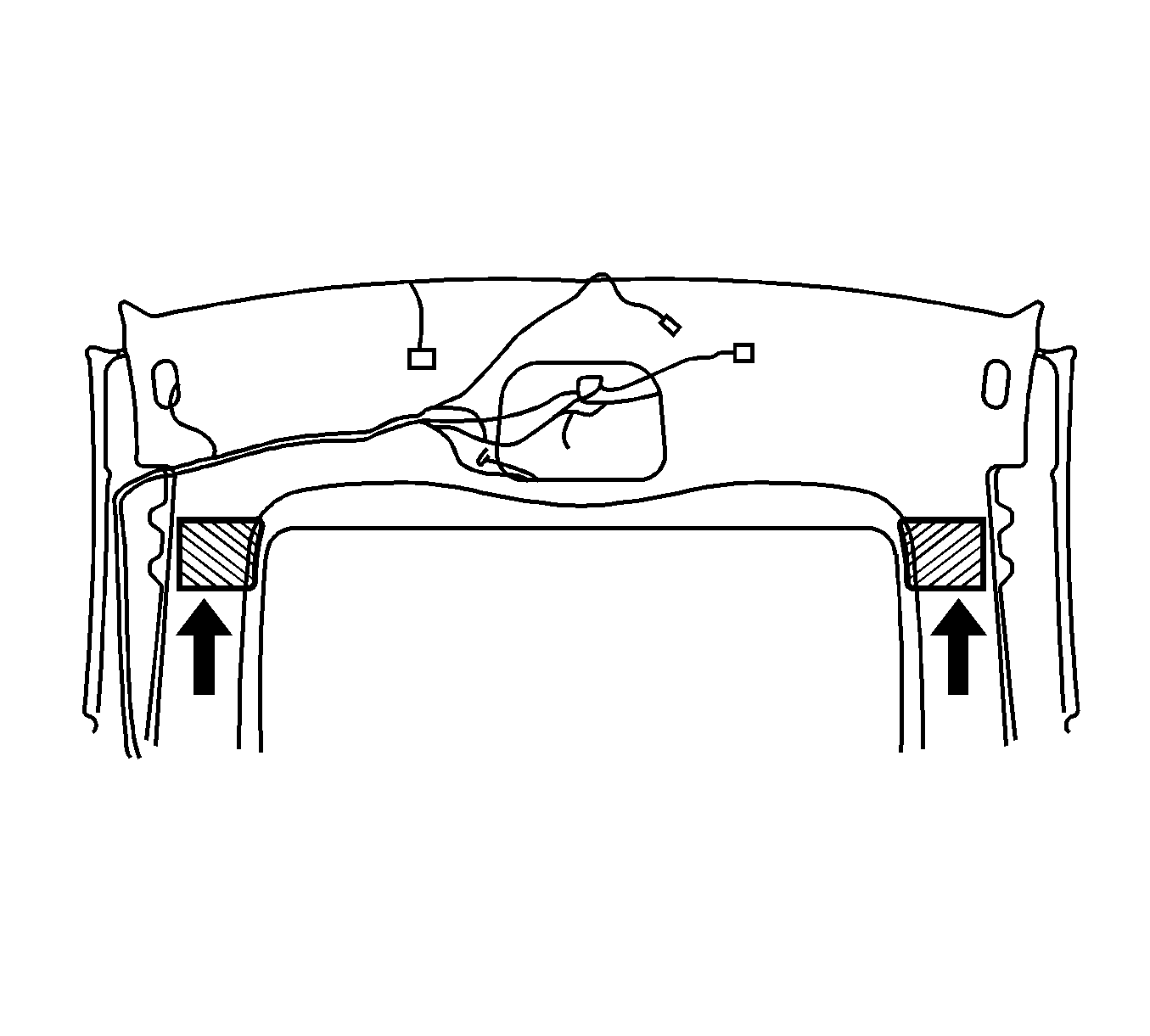
For vehicles built before May 9, 2005, (Note: vehicles built after May 9, 2005, already has this update) partially lower the front of the headliner enough to access this area, being careful not to bend or damage the headliner while performing the following procedure. Install a 102 mm X 102 mm (4 in X 4 in) felt/flocking tape* patch to the backside of the headliner, just under the pair of plastic screw boss holes (empty/no screws in these bosses) that are part of the sunroof module on each side of the module (driver/passenger) towards the front (refer to figure 26).
VERIFY CUSTOMER COMPLAINT HAS BEEN ELIMINATED Reinstall the headliner. *The felt/flocking tape, BSR P/N KT13296, can be purchased from Kent Automotive by calling 1-800-654-6333 (in Canada, 1-800-563-1717).
Condition #11
Some customers may comment of a squeak or itch noise over bumps at the rear of the sunroof.
Cause
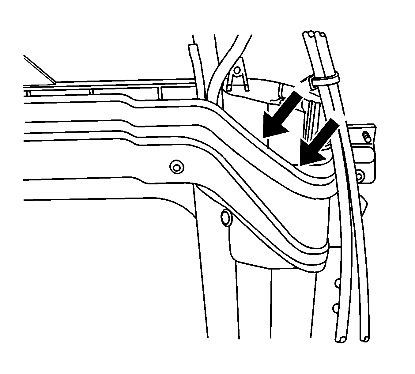
The metal frame of the sunroof module may be contacting the plastic portion of the sunroof module.
Correction
Loosen the metal frame and insert a piece of 3M™ squeak reduction tape, P/N 06356, between the plastic and metal frame.
Parts Information
Part Number | Description | Qty |
|---|---|---|
15911310 | Condition #1 28 Mylar Washers | 2 packages (14 per package) |
25866125 | Condition #2 Sealing Strip, RF Panel (Cross Car Foam) | Order 3 per vehicle |
25866123 | Condition #3 Seal Sun RF WDO | Order 1 per vehicle |
Warranty Information
The intent of this bulletin is to identify the appropriate issue/s and apply the appropriate correction(s) pertaining to the customer's comments. To determine the final service labor operation time, use the initial base time and then apply the appropriate add times depending on the issue correction(s) performed. Please note - only the items performed on the vehicle being serviced should be used as the final repair time and the Repair Order must indicate the Bulletin Number and the Condition Number(s) used.
Labor Operation | Description | Labor Time |
|---|---|---|
B9826* | Road Test and Inspect | 0.2 hr |
ADD | Condition #1 | 0.9 hr |
ADD | Condition #2 | 0.3 hr |
ADD | Condition #3A | 0.9 hr |
ADD | Condition #3C | 0.5 hr |
ADD | Condition #4 | 0.2 hr |
ADD | Condition #5 | 0.6 hr |
ADD | Condition #6 | 0.9 hr |
ADD | Condition #7 | 0.2 hr |
ADD | Condition #10 | 0.6 hr |
ADD | Condition #11 | 0.6 hr |
*This is a unique labor operation for bulletin use only. It will not be published in the Labor Time Guide. | ||
IMPORTANT NOTE WHEN PRINTING THIS FORM: If the form prints out on two pages, make certain you fax BOTH pages so that the WPC receives all the needed information. Missing information will delay or prevent the part from being shipped.
Parts Request Form - Warranty Parts Center |
|---|
To: Warranty Parts Center
e-mail: warrantypartscenterUSA@gm.com
or WPC Fax: 248-371-0192
Attn: Jeannette Dunn
Part Being Requested (please circle correct P/N):
WPC401 - GLASS PANEL PINS (set of 2)
Dealer BAC (U.S.) / Dealer Code (Canada):
Dealer Name:
Dealer Address:
Dealer Contact Person:
Dealer Phone Number:
Repair Order Number:
Vehicle VIN:
Important: If you do not receive the part within 2 business days after e-mailing or faxing your part request to the Warranty Parts Center, please call Customer Assistance at 248-371-9901/9902. IMPORTANT NOTE WHEN PRINTING THIS FORM: If the form prints out on two pages, make certain you fax BOTH pages so that the WPC receives all the needed information. Missing information will delay or prevent the part from being shipped. |
