Malfunction Indicator Lamp On - Check Engine Light, DTCs P0011, P0014, P0021, P0024, P0341, P0346, P0366 or P0391 Set (Check Camshaft End Play and Perform Action as Outlined)

| Subject: | Malfunction Indicator Lamp On -- Check Engine Light, DTCs P0011, P0014, P0021, P0024, P0341, P0346, P0366, or P0391 Set (Check Camshaft End Play and Perform Action as Outlined) |
| Models: | 2007-2008 Buick LaCrosse, Allure (Canada Only) |
| 2008 Buick Enclave |
| 2007-2008 Cadillac CTS, SRX, STS |
| 2008 Chevrolet Equinox, Malibu |
| 2007-2008 GMC Acadia |
| 2007-2008 Pontiac G6 |
| 2008 Pontiac G8, Torrent |
| 2007-2008 Saturn AURA, OUTLOOK |
| 2008 Saturn VUE |
| with 2.8L or 3.6L High Feature V6 Engine (VINs T, V, 7 -- RPOs LP1, LLT, LY7) |
| Attention: | This bulletin also applies to any of the above models that may also be export vehicles. |
This bulletin is being revised to update the correction and warranty information. Please discard Corporate Bulletin Number 08-06-01-011A (Section 06 -- Engine/Propulsion System).
Condition
Some customers may comment that the check engine light is on.
Upon investigation, the technician may find one or more of the following DTCs stored:
| • | P0011 |
| • | P0014 |
| • | P0021 |
| • | P0024 |
| • | P0341 |
| • | P0346 |
| • | P0366 |
| • | P0391 |
Correction
Step | Action | Yes | No |
|---|---|---|---|
1 | Is vehicle an Acadia, Enclave or Outlook with P0011, P0014, P0021 or P0024? | Go to Step 2 | Go to Step 3 |
2 | Reprogram the ECM. Refer to Service Bulletin 08-06-04-011 for further information. Do P0011, P0014, P0021 or P0024 still set? | Go to Step 3 | Return vehicle to customer |
3 |
Important: The set DTC will determine which camshafts (bank 1 or bank 2) should be checked. Remove the camshaft cover and check camshaft end play on both camshafts in the suspect head using one of the methods listed below. Is camshaft end play equal to or over 0.40 mm (0.016 in)? | Go to Step 5 | Go to Step 4 |
4 | Continue diagnosis using SI and call GM Technical Assistance, if necessary. | - | - |
5 | Check the gap between BOTH camshaft position actuators and the front camshaft cap using the Camshaft Position Actuator to Front Camshaft Cap Measurement Procedure listed below. Does the 2.5 mm hex (allen) wrench fit between the position actuator and cap? | Go to Step 7 | Go to Step 6 |
6 | Install the camshaft thrust washers using the Camshaft Thrust Washer Installation Procedure listed below. | - | - |
7 | Replace the cylinder head and install thrust washers using the Camshaft Thrust Washer Installation Procedure listed below. | - | - |
Camshaft End Play Measurement Procedure
Remove the camshaft cover from the suspect cylinder head.
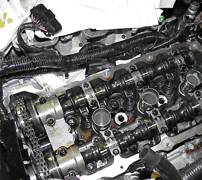
Two methods for measuring camshaft end play:
Method 1: Dial Indicator
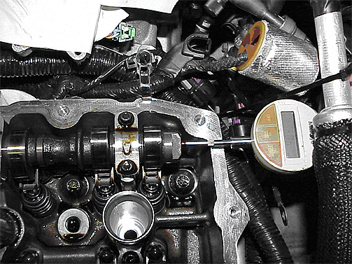
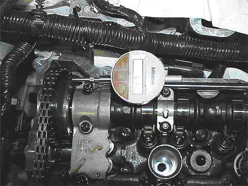
| • | Set-up a dial indicator on the camshaft to be measured. Set the dial indicator to measure the axial movement of the camshaft. To minimize measurement error, the dial indicator needs to be on the same axis as the camshaft. A magnetic mount can be placed on the frame rail or a piece of steel plate can be bolted to the top of the head as a reference surface for the dial indicator. The dial indicator should have 0.1 mm (.001 in) of resolution. |
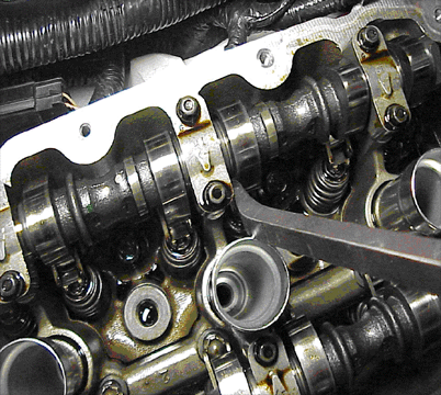
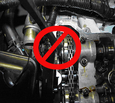
| • | Position a screwdriver or small pry bar between the camshaft cap and camshaft lobe. Apply force to move the camshaft rearward. |
| • | Be cautious not to damage the camshaft lobe while applying this force. |
| • | Zero the dial indicator. |
| • | Apply force to move the camshaft forward (towards the camshaft phasers). |
| • | Read the dial indicator. This is the end play of the camshaft shaft. |
Notice: Do not use the phaser bolt as a pry point. This may cause damage to the camshaft sensor target wheel or the head to camshaft cover sealing surface.
Method 2: Caliper
The caliper should have 0.1 mm (.001") of resolution.
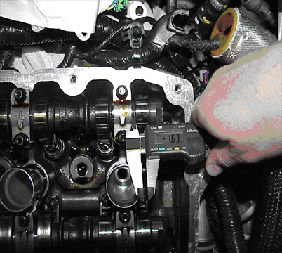
| • | Position a screwdriver or medium pry bar between the camshaft cap and camshaft lobe. Be cautious not to damage the camshaft lobe while applying this force. |
| • | Apply force to move the camshaft rearward. |
| • | Measure and record the distance between the camshaft cap and the camshaft lobe. |
| • | Re-measure and record the distance between the camshaft cap and camshaft lobe. Subtract the two readings; this is the camshaft shaft end play. |
Camshaft Position Actuator to Front Camshaft Cap Measurement Procedure
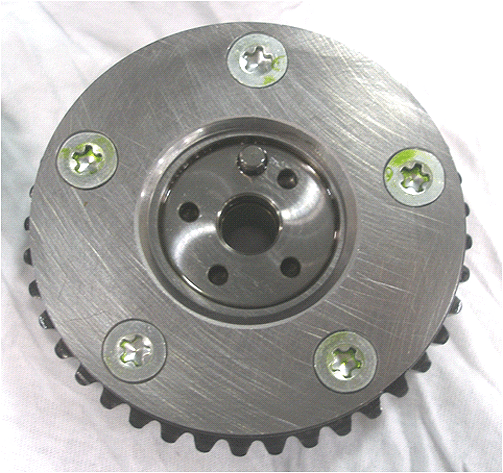
Aisin Actuator
Delphi Actuator
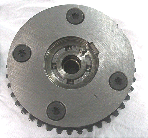
Important: Before performing this procedure, inspect the rear of the camshaft position actuator. If there are five screws (Aisin Actuator) in the rear of the camshaft position actuator, proceed with this procedure. If there are four screws (Delphi Actuator) in the rear of the camshaft position actuator, this procedure CANNOT be used. Call GM Technical Assistance for direction.
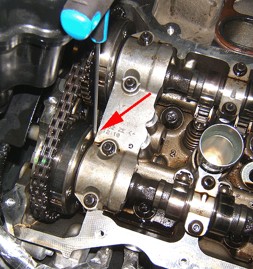
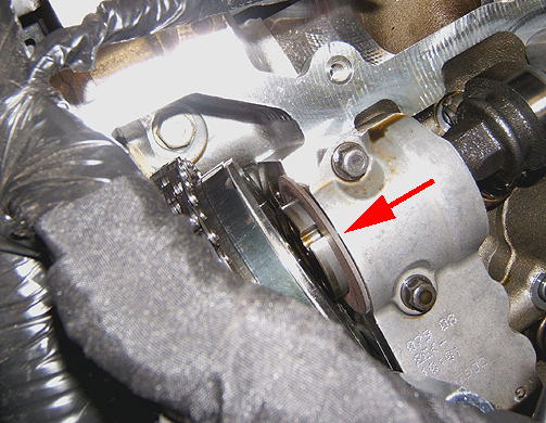
Use a 2.5 mm hex (allen) wrench as a determination gauge to measure the gap between the rear of the camshaft position actuator and the front camshaft cap of both camshafts of the suspect head.
- Position a screwdriver or medium pry bar between the camshaft cap and camshaft lobe.
- Apply force to move the camshaft FORWARD. Be cautious not to damage the camshaft lobe while applying this force.
- With the camshaft moved fully FORWARD, try to insert the 2.5 mm hex (allen) wrench between the intake camshaft position actuator and the front camshaft cap. It may be necessary to turn the wrench to align the flat sides of the wrench with the gap between the actuator and the cap.
- If the wrench fits between the camshaft position actuator and the front camshaft cap, it will be necessary to replace the cylinder head assembly (refer to the Cylinder Head Replacement procedure in SI) with the appropriate part number listed in this bulletin. WHEN REPLACING THE CYLINDER HEAD, ALSO INSTALL A THRUST WASHER BETWEEN EACH CAMSHAFT POSITION ACTUATOR AND THE FRONT CAMSHAFT CAP.
- If the wrench DOES NOT fit between the camshaft position actuator and the front camshaft cap, install the camshaft thrust washers between BOTH camshaft position actuators and the front camshaft cap on the suspect head. Follow the Camshaft Thrust Washer Installation procedure below.
Important: Prior to replacing a cylinder head assembly, dealers will need to call the PQC at 1-866-654-7654.
Camshaft Thrust Washer Installation Procedure
Tip
The cylinder head gasket kit contains all the gaskets and seals necessary to perform this repair. Thrust washers should be ordered through the Warranty Parts Center using the form at the end of this bulletin.
- Disconnect the engine wiring harness electrical connectors from the intake and exhaust camshaft position (CMP) actuator solenoid valves and sensors.
- Remove the intake and exhaust CMP sensor bolts and sensors.
- Remove the intake and exhaust CMP actuator solenoid valve bolts and valves.
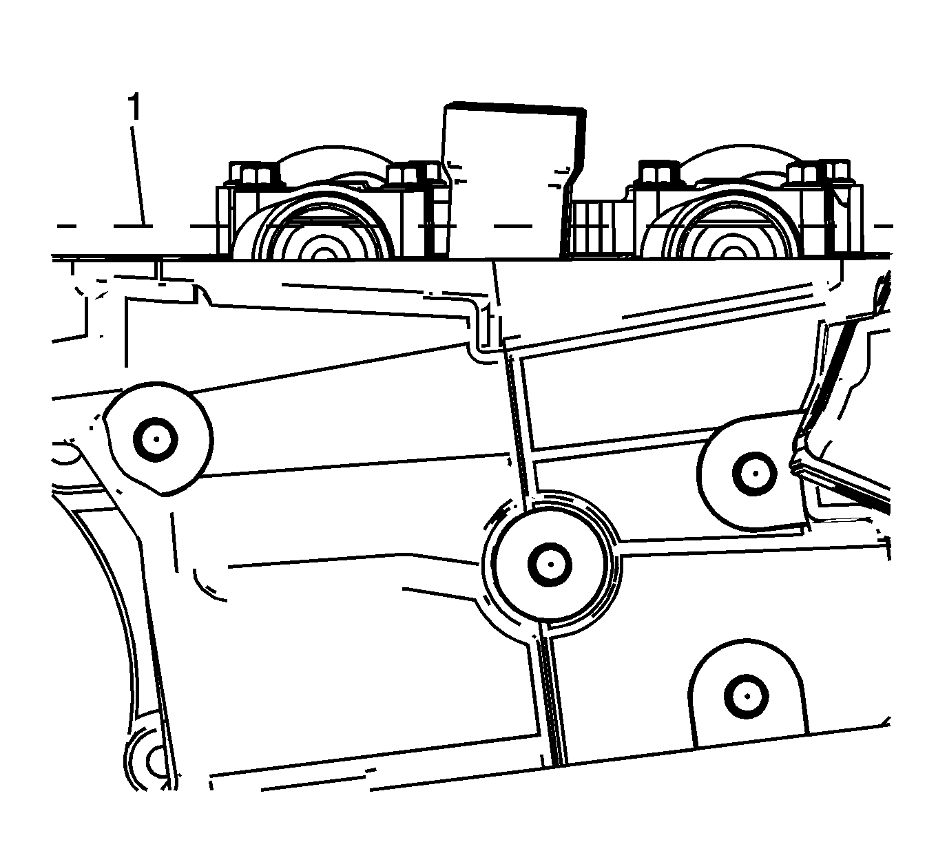
- Rotate the crankshaft balancer using the balancer bolt until the camshafts are in a neutral (low tension) position. The flats on the rear of the camshafts will be parallel with the camshaft cover rail (1).
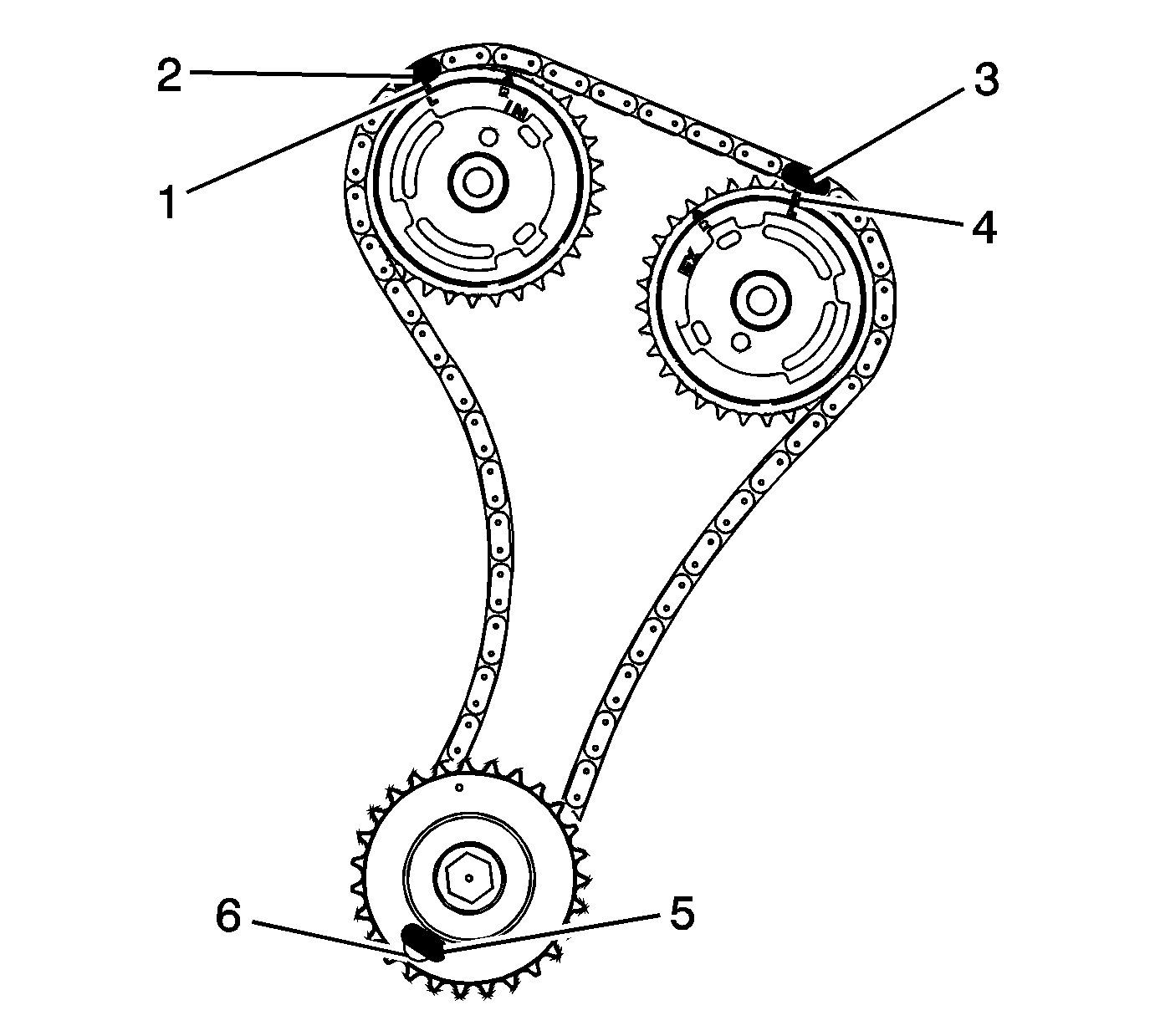
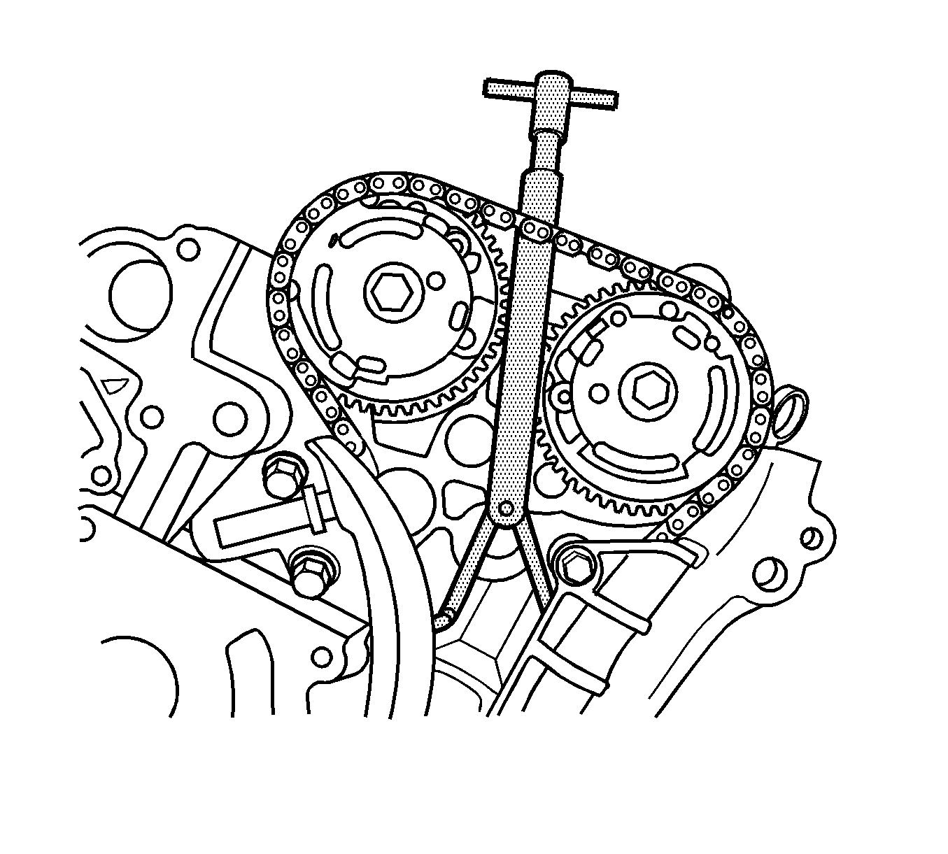
- Use a paint stick to create an alignment mark on one of the timing chain links (2) and the adjacent tooth on the exhaust camshaft position actuator (1).
- Use a paint stick to create an alignment mark on one of the timing chain links (3) and the adjacent tooth on the intake camshaft position actuator (4).
- Use an open end wrench on the hex cast into the camshaft in order to prevent engine rotation when loosening the camshaft position actuator bolts. Slightly loosen the camshaft position actuator bolts. DO NOT remove the bolts.
- Unscrew the Timing Chain Retention Tool EN-48313 so that the legs of the tool are retracted.
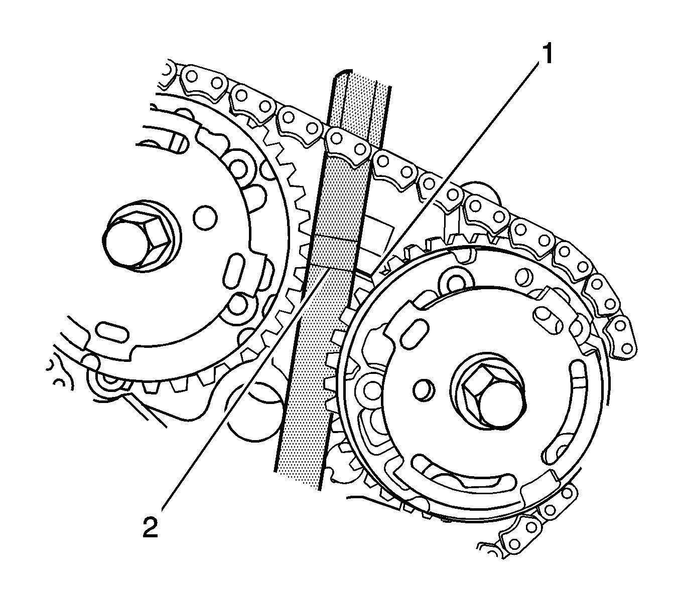
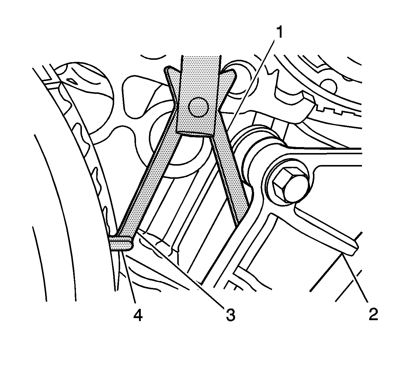
- Insert the Timing Chain Retention Tool EN-48313 between the camshaft actuators, rearward of the timing chain until the bottom line that is scribed in the body of the tool (2) is adjacent to the top surface of the cylinder head (1). This is the approximate installed position.
- Ensure that the feet (4) on the legs of the tool are facing the front of the engine.
- Partially expand the legs (1, 3) of the Timing Chain Retention Tool EN-48313 by turning the T-shaped handle clockwise.
- Insert the leg of the tool (1) behind the timing chain guide (2).
- Continue expanding the Timing Chain Retention Tool EN-48313 until the legs (1, 3) contact the timing chain. Do not tighten at this time.
- Hand tighten the Timing Chain Retention Tool EN-48313. If installed correctly, there should be a small amount of slack in the timing chain between the camshaft position actuator sprockets.
- The Timing Chain Retention Tool EN-48313 is now properly installed to hold the timing chain in position.
- Remove the intake camshaft position actuator bolt.
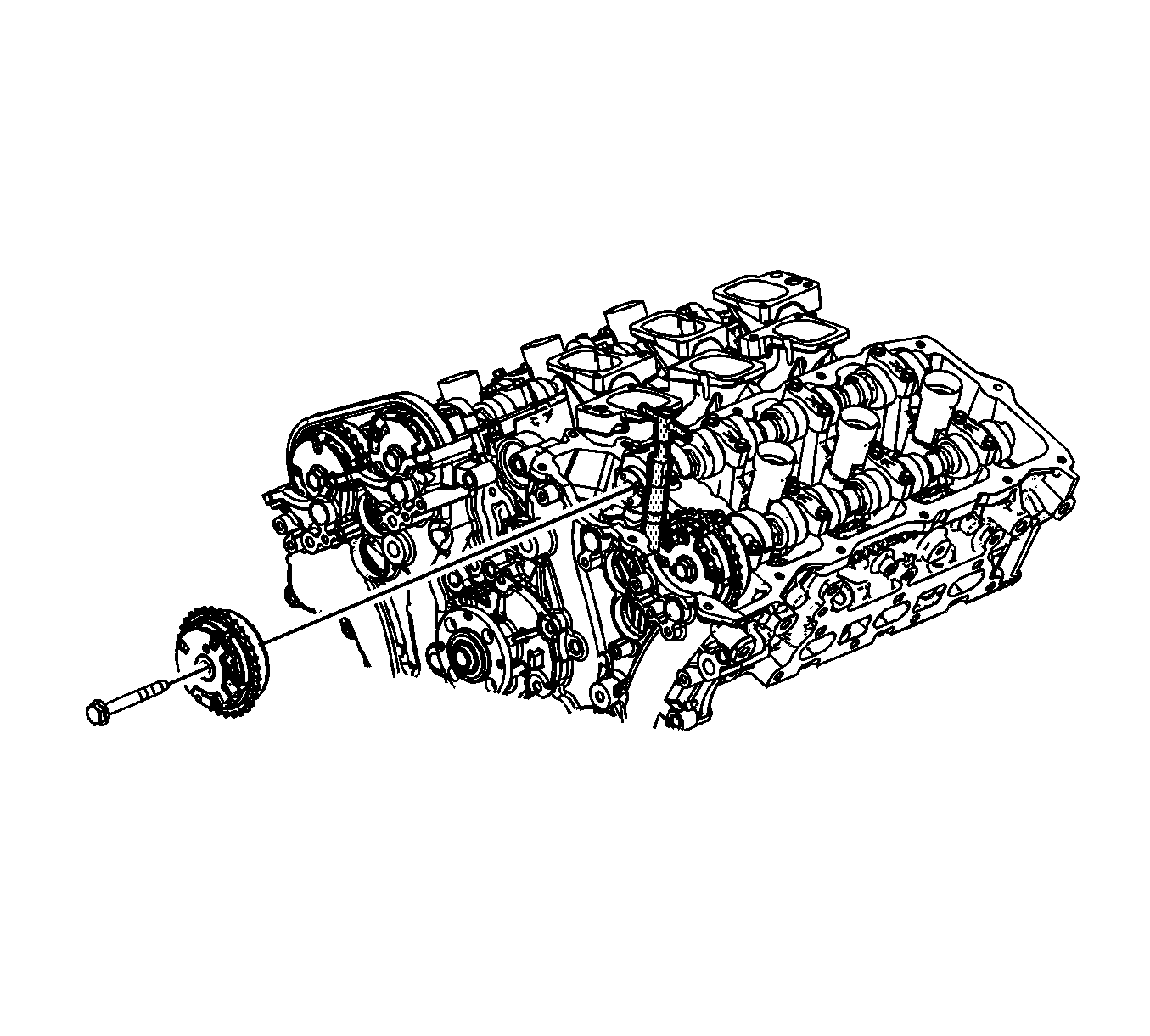
- Move the camshaft position actuator forward enough to slip the camshaft thrust washer over the front of the intake camshaft and position it against the cylinder head.
- Position the intake camshaft actuator to the camshaft and install the actuator bolt hand tight. If necessary, slightly rotate the camshaft to engage the timing pin.
- Remove the exhaust camshaft position actuator bolt.
- Move the camshaft position actuator forward enough to slip the camshaft thrust washer over the front of the exhaust camshaft and position it against the cylinder head.
- Position the exhaust camshaft actuator to the camshaft and install the actuator bolt hand tight. If necessary, slightly rotate the camshaft to engage the timing pin.
- Remove the Timing Chain Retention Tool EN-48313.
- Tighten the intake and exhaust camshaft position actuator bolts. Use an open end wrench on the hex cast into the camshaft in order to prevent engine rotation when tightening the camshaft position actuator bolts. Verify that the paint marks on the timing chain and camshaft position actuators are aligned.
- Install the intake and exhaust camshaft position actuator solenoid valves and bolts.
- Install the intake and exhaust camshaft position sensors and bolts.
- Connect the engine wiring harness electrical connectors to the intake and exhaust camshaft position (CMP) sensors and actuator solenoid valves.
Important: Rotate the crankshaft balancer bolt in a clockwise direction ONLY.
Important: The engine front cover is removed for clarity in the following graphics, but NOT required to perform the procedure.
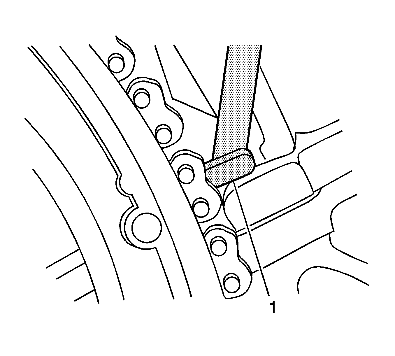
Important: Ensure that the foot (1) of the Timing Chain Retention Tool EN-48313 is engaged into one of the link pockets to prevent tool slippage during tightening of the Timing Chain Retention Tool EN-48313.
Tip
It is not necessary to completely remove the camshaft actuator from the engine in order to install the thrust washers.

Tighten
Tighten the bolts to 58 N·m (43 lb ft).
Tighten
Tighten the bolts to 10 N·m (89 lb in).
Tighten
Tighten the bolts to 10 N·m (89 lb in).
Parts Information
To obtain the camshaft thrust washer, fax the form included in this bulletin to the GM Warranty Parts Center (WPC). Request WPC #442.
Part Number | Description |
|---|---|
12626907 (Left LY7 Standard All Models Excluding Enclave, Acadia, Outlook) | Complete Cylinder Head Assembly |
12626908 (Right LY7 Standard All Models Excluding Enclave, Acadia, Outlook) | Complete Cylinder Head Assembly |
12626909 (Left LY7 High Output Enclave, Acadia, Outlook) | Complete Cylinder Head Assembly |
12626910 (Right LY7 High Output Enclave, Acadia, Outlook) | Complete Cylinder Head Assembly |
12626911 (Left LLT) | Complete Cylinder Head Assembly |
12626912 (Right LLT) | Complete Cylinder Head Assembly |
12626913 (Left LP1) | Complete Cylinder Head Assembly |
12626914 (Right LP1) | Complete Cylinder Head Assembly |
11518863 | Cylinder Head Bolt (8 required per head) |
12591003 (LLT Only) | Fuel Injection Fuel Rail Crossover Tube |
12591197 (LLT Only) | Fuel Feed Intermediate Pipe |
Important: When ordering the cylinder head gasket for cylinder head replacement, the kit does not include the M11 head bolts or exhaust manifold gaskets, which will need to be ordered separately.
For part numbers and usage of necessary gaskets, refer to Group 00 6-Cylinder Engine of the appropriate Parts Catalog. Saturn Retailers should refer to the appropriate Parts & Illustration Catalog for the vehicle.
Warranty Information (Thrust Washer Installation) (2007-08 Buick LaCrosse/Allure)
For vehicles repaired under warranty, use:
Labor Operation | Description | Labor Time |
|---|---|---|
J7534* | Check Camshaft End Play Right Bank | 1.8 hrs** |
Add | To Install Thrust Washer Right Bank | 0.4 hr |
J7535* | Check Camshaft End Play Left Bank | 2.4 hrs** |
Add | To Install Thrust Washer Left Bank | 0.4 hr |
J7536* | Check Camshaft End Play Both Banks | 3.0 hrs** |
Add | To Install Thrust Washer Both Banks | 0.8 hr |
* This labor operation number is for bulletin use only. This number will not be published in the Labor Time Guide. **This time includes R&R cam cover. | ||
Warranty Information (Cylinder Head Replacement) (2007-08 Buick LaCrosse/Allure)
For vehicles repaired under warranty, use:
Labor Operation | Description | Labor Time |
|---|---|---|
J7528* | Check Camshaft End Play Right Bank | 1.8 hrs** |
Add | To Replace Complete Cylinder Head Assembly Right Bank | 5.5 hrs |
J7529* | Check Camshaft End Play Left Bank | 2.4 hrs** |
Add | To Replace Complete Cylinder Head Assembly Left Bank | 6.9 hrs |
J7530* | Check Camshaft End Play Both Banks | 3.0 hrs** |
Add | To Replace Complete Cylinder Head Assembly Both Banks | 7.6 hrs |
* This labor operation number is for bulletin use only. This number will not be published in the Labor Time Guide. **This time includes R&R cam cover. | ||
Warranty Information (Thrust Washer Installation) (2007-08 Cadillac CTS/SRX/STS, 2008 Pontiac G8)
For vehicles repaired under warranty, use:
Labor Operation | Description | Labor Time |
|---|---|---|
J7534* | Check Camshaft End Play Right Bank | 2.0 hrs** |
Add | To Install Thrust Washer Right Bank | 0.4 hr |
J7535* | Check Camshaft End Play Left Bank | 2.0 hrs** |
Add | To Install Thrust Washer Left Bank | 0.4 hr |
J7536* | Check Camshaft End Play Both Banks | 2.4 hrs** |
Add | To Install Thrust Washer Both Banks | 0.8 hr |
* This labor operation number is for bulletin use only. This number will not be published in the Labor Time Guide. **This time includes R&R cam cover. | ||
Warranty Information (Cylinder Head Replacement) (2007-08 Cadillac CTS/SRX/STS, 2008 Pontiac G8)
For vehicles repaired under warranty, use:
Labor Operation | Description | Labor Time |
|---|---|---|
J7528* | Check Camshaft End Play Right Bank | 2.0 hrs** |
Add | To Replace Complete Cylinder Head Assembly Right Bank | 7.4 hrs |
J7529* | Check Camshaft End Play Left Bank | 2.0 hrs** |
Add | To Replace Complete Cylinder Head Assembly Left Bank | 7.9 hrs |
J7530* | Check Camshaft End Play Both Banks | 2.4 hrs** |
Add | To Replace Complete Cylinder Head Assembly Both Banks | 8.2 hrs |
* This labor operation number is for bulletin use only. This number will not be published in the Labor Time Guide. **This time includes R&R cam cover. | ||
Warranty Information (Thrust Washer Installation) (2008 Chevrolet Equinox/Malibu, 2007-08 Pontiac G6, 2008 Pontiac Torrent, 2007-08 Saturn AURA)
For vehicles repaired under warranty, use:
Labor Operation | Description | Labor Time |
|---|---|---|
J7534* | Check Camshaft End Play Right Bank | 1.4 hrs** |
Add | To Install Thrust Washer Right Bank | 0.4 hr |
J7535* | Check Camshaft End Play Left Bank | 1.1 hrs** |
Add | To Install Thrust Washer Left Bank | 0.4 hr |
J7536* | Check Camshaft End Play Both Banks | 1.7 hrs** |
Add | To Install Thrust Washer Both Banks | 0.8 hr |
* This labor operation number is for bulletin use only. This number will not be published in the Labor Time Guide. **This time includes R&R cam cover. | ||
Warranty Information (Cylinder Head Replacement) (2008 Chevrolet Equinox/Malibu, 2007-08 Pontiac G6, 2008 Pontiac Torrent, 2007-08 Saturn AURA)
For vehicles repaired under warranty, use:
Labor Operation | Description | Labor Time |
|---|---|---|
J7528* | Check Camshaft End Play Right Bank | 1.4 hrs** |
Add | To Replace Complete Cylinder Head Assembly Right Bank | 5.1 hrs |
J7529* | Check Camshaft End Play Left Bank | 1.1 hrs** |
Add | To Replace Complete Cylinder Head Assembly Left Bank | 5.2 hrs |
J7530* | Check Camshaft End Play Both Banks | 1.7 hrs** |
Add | To Replace Complete Cylinder Head Assembly Both Banks | 5.5 hrs |
* This labor operation number is for bulletin use only. This number will not be published in the Labor Time Guide. **This time includes R&R cam cover. | ||
Warranty Information (Thrust Washer Installation) (2008 Buick Enclave, 2007-08 GMC Acadia, 2007-08 Saturn OUTLOOK)
For vehicles repaired under warranty, use:
Labor Operation | Description | Labor Time |
|---|---|---|
J7534* | Check Camshaft End Play Right Bank | 2.1 hrs** |
Add | To Install Thrust Washer Right Bank | 1.6 hrs*** |
J7535* | Check Camshaft End Play Left Bank | 2.3 hrs** |
Add | To Install Thrust Washer Left Bank | 1.6 hrs*** |
J7536* | Check Camshaft End Play Both Banks | 2.6 hrs** |
Add | To Install Thrust Washer Both Banks | 2.0 hrs*** |
* This labor operation number is for bulletin use only. This number will not be published in the Labor Time Guide. **This time includes R&R cam cover. ***This time includes R&R underhood electrical center and engine mount. | ||
Warranty Information (Cylinder Head Replacement) (2008 Buick Enclave, 2007-08 GMC Acadia, 2007-08 Saturn OUTLOOK)
For vehicles repaired under warranty, use:
Labor Operation | Description | Labor Time |
|---|---|---|
J7528* | Check Camshaft End Play Right Bank | 2.1 hrs** |
Add | To Replace Complete Cylinder Head Assembly Right Bank | 4.8 hrs |
J7529* | Check Camshaft End Play Left Bank | 2.3 hrs** |
Add | To Replace Complete Cylinder Head Assembly Left Bank | 4.6 hrs |
J7530* | Check Camshaft End Play Both Banks | 2.6 hrs** |
Add | To Replace Complete Cylinder Head Assembly Both Banks | 4.9 hrs |
* This labor operation number is for bulletin use only. This number will not be published in the Labor Time Guide. **This time includes R&R cam cover. | ||
Warranty Information (Thrust Washer Installation) (2008 Saturn VUE)
For vehicles repaired under warranty, use:
Labor Operation | Description | Labor Time |
|---|---|---|
J7534* | Check Camshaft End Play Right Bank | 1.5 hrs** |
Add | To Install Thrust Washer Right Bank | 1.2 hrs*** |
J7535* | Check Camshaft End Play Left Bank | 0.8 hr** |
Add | To Install Thrust Washer Left Bank | 1.2 hrs*** |
J7536* | Check Camshaft End Play Both Banks | 1.8 hrs** |
Add | To Install Thrust Washer Both Banks | 1.6 hrs*** |
* This labor operation number is for bulletin use only. This number will not be published in the Labor Time Guide. **This time includes R&R cam cover. ***This time includes R&R engine mount. | ||
Warranty Information (Cylinder Head Replacement) (2008 Saturn VUE)
For vehicles repaired under warranty, use:
Labor Operation | Description | Labor Time |
|---|---|---|
J7528* | Check Camshaft End Play Right Bank | 1.5 hrs** |
Add | To Replace Complete Cylinder Head Assembly Right Bank | 7.7 hrs |
J7529* | Check Camshaft End Play Left Bank | 0.8 hr** |
Add | To Replace Complete Cylinder Head Assembly Left Bank | 7.7 hrs |
J7530* | Check Camshaft End Play Both Banks | 1.8 hrs** |
Add | To Replace Complete Cylinder Head Assembly Both Banks | 8.0 hrs |
* This labor operation number is for bulletin use only. This number will not be published in the Labor Time Guide. **This time includes R&R cam cover. | ||
IMPORTANT NOTE WHEN PRINTING THIS FORM: If the form prints out on two pages, make certain you fax BOTH pages so that the WPC receives all the needed information. Missing information will delay or prevent the part from being shipped.
Parts Request Form - Warranty Parts Center |
|---|
To: Warranty Parts Center
e-mail: warrantypartscenterUSA@gm.com
or WPC Fax: 248-371-0192
Attn: Jeanette Dunn
Part Being Requested: Camshaft Thrust Washer WPC #442 (set of 2 washers)
Dealer BAC (U.S.) / Dealer Code (Canada):
Dealer Name:
Dealer Address:
Dealer Contact Person:
Dealer Phone Number:
Repair Order Number:
Vehicle VIN:
Important: If you do not receive the part within 2 business days after e-mailing or faxing your part request to the Warranty Parts Center, please call Customer Assistance at 248-371-9901/9902. IMPORTANT NOTE WHEN PRINTING THIS FORM: If the form prints out on two pages, make certain you fax BOTH pages so that the WPC receives all the needed information. Missing information will delay or prevent the part from being shipped. |
