For 1990-2009 cars only
Special Tools
J 42129 Wheel Hub Removal
Removal Procedure
- Raise the vehicle. Refer to Lifting and Jacking the Vehicle.
- Remove the tire and wheel assembly. Refer to Tire and Wheel Removal and Installation.
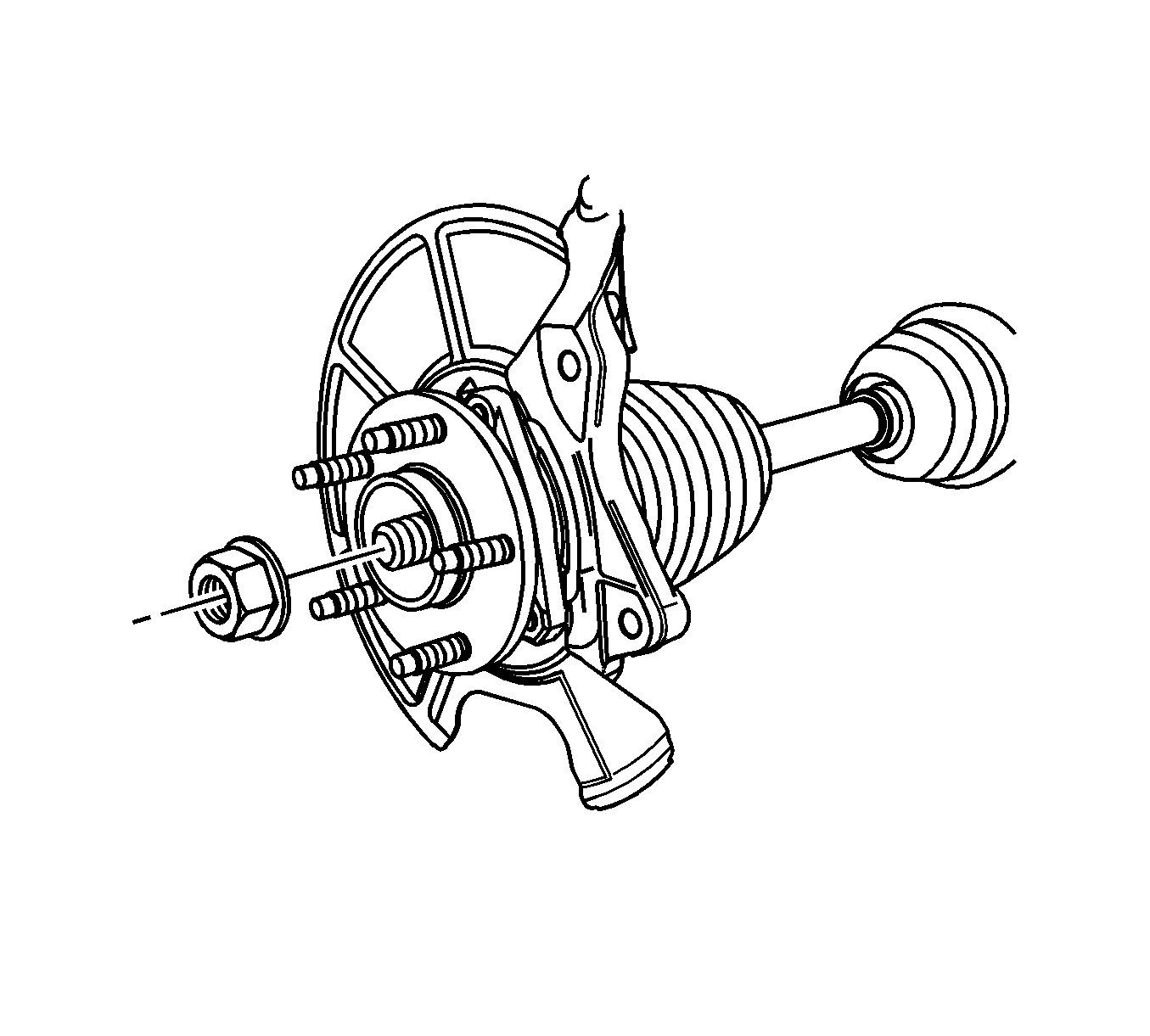
- Remove the wheel drive shaft nut.
- Remove the brake rotor. Refer to Front Brake Rotor Replacement.
- Disconnect the electrical connector from the wheel speed sensor.
- Remove the wheel speed sensor connector from the bracket by depressing the locking tabs.
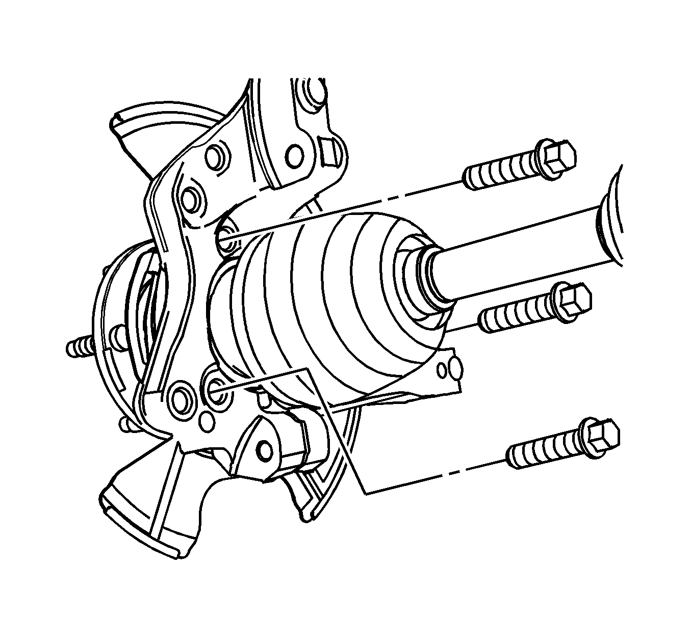
- Remove the 3 hub and bearing assembly bolts.
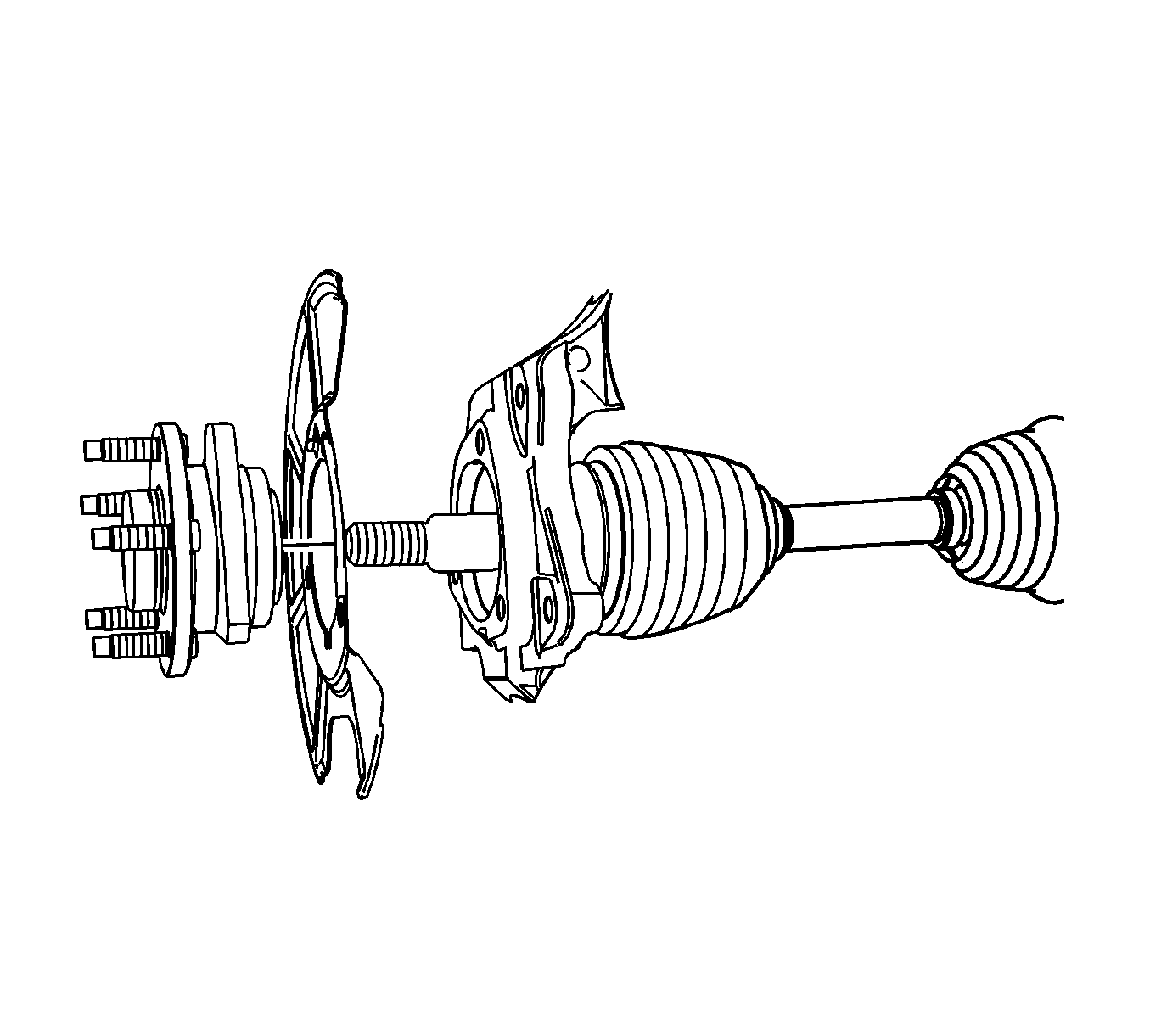
- Install the J 42129 to the hub and bearing assembly in order to remove the hub and bearing assembly from the wheel drive shaft.
- Remove the hub and bearing assembly from the steering knuckle.


Caution: Avoid tool contact to the outer constant velocity boot when removing the wheel bearing mounting bolts. Failure to observe this caution may result in damage to the CV boot.

Installation Procedure
- Install the hub and bearing assembly to the steering knuckle.
- Install the 3 hub and bearing assembly bolts and tighten to 115 N·m (85 lb ft.
- Install the wheel speed sensor connector into the bracket until the locking tabs click into place.
- Connect the electrical connector to the wheel speed sensor.
- Install the axle nut to the wheel drive shaft, hand tighten the wheel drive shaft nut.
- Install the brake rotor. Refer to Front Brake Rotor Replacement.
- Install the wheel drive shaft nut to the wheel drive shaft.
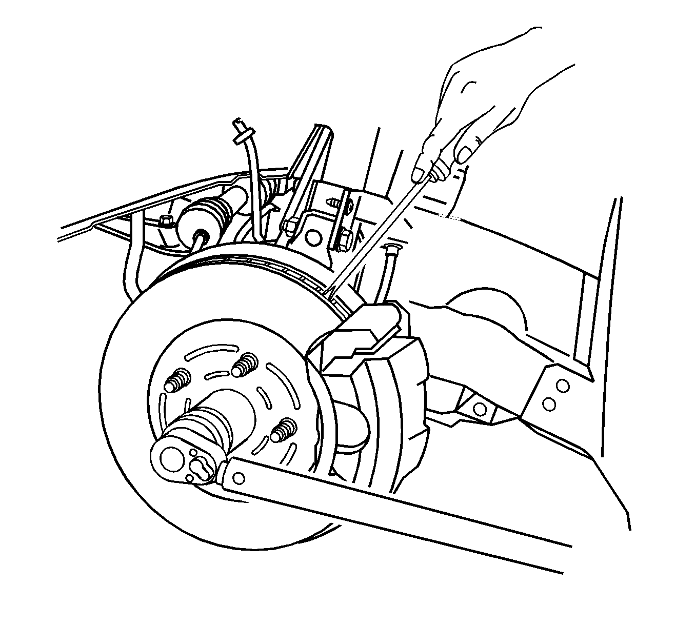
- Use a screw driver or similar tool to stop the rotation of the brake rotor and tighten to 215 N·m (159 lb ft).
- Install the tire and wheel assemblies. Refer to Tire and Wheel Removal and Installation.

Caution: Refer to Fastener Caution in the Preface section.

Caution: This is a self-retaining fastener joint that does not require thread locking compounds. Do not attempt to clean the threads with a standard tap. If a standard tap is used, damage to the joint threads will occur.


