For 1990-2009 cars only
Special Tools
J 45059 Angle Meter
Removal Procedure
- Raise and support the vehicle. Refer to Lifting and Jacking the Vehicle.
- Remove the rear tire and wheel assembly. Refer to Tire and Wheel Removal and Installation.
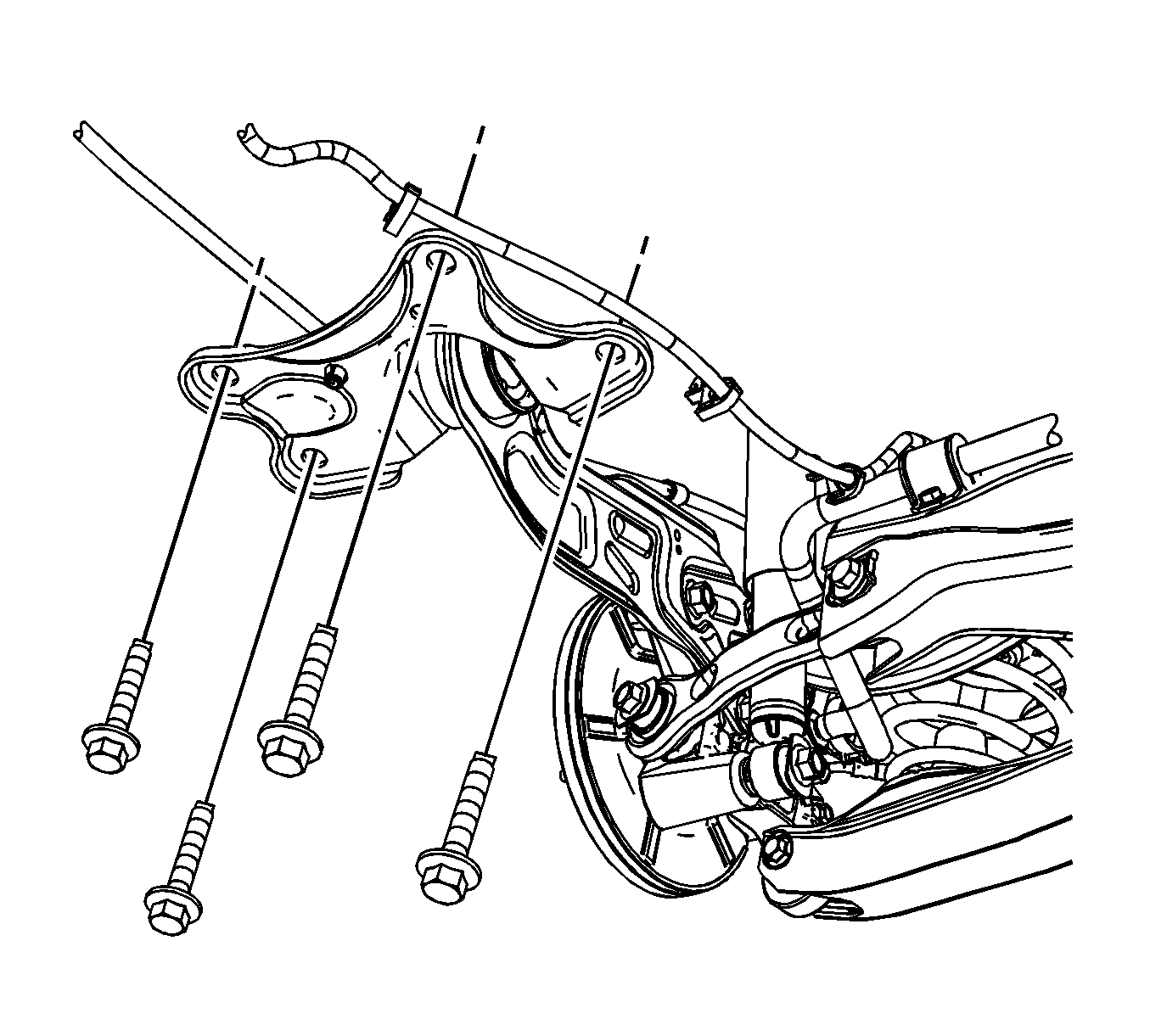
- Remove the 4 trailing arm bracket to body bolts.
- Remove the rear parking brake cable routing bolt from the trailing arm.
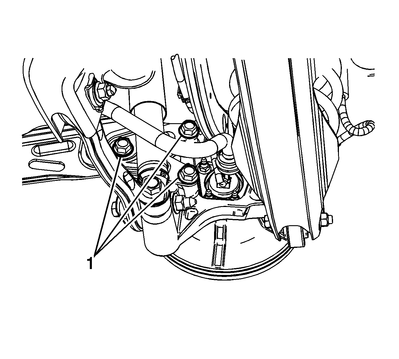
- Remove the 3 trailing arm to knuckle through bolts (1).
- Disconnect the park brake cable routing clip from the trailing arm bracket.
- Remove the trailing arm and bracket as an assembly from the vehicle.
- Place trailing arm and bracket as an assembly on a work bench.
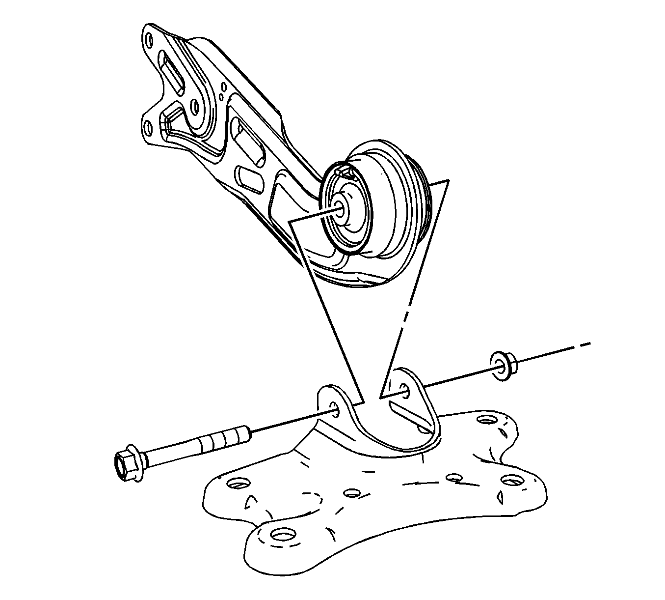
- Remove the trailing arm to bracket bolt and nut.
- Separate the trailing arm bracket from the trailing arm.


Installation Procedure
- Position the trailing arm to the bracket, install the bolt and nut.
- Position the trailing arm and bracket assembly to the vehicle.
- Connect the park brake cable routing clip to the trailing arm bracket.
- Install the 3 trailing arm to knuckle bolts (1).
- Install the rear parking brake cable routing bolt to the trailing arm. Refer to Parking Brake Rear Cable Replacement.
- Install the trailing arm bracket to body bolts.
- Install the rear tire and wheel assembly. Refer to Tire and Wheel Removal and Installation.
- Lower the vehicle.
Caution: Refer to Fastener Caution in the Preface section.

Tighten
Tighten the trailing arm to bracket through bolt and nut to 60 N·m (44 lb ft) plus 60 degrees.

Tighten
Tighten the 3 trailing arm to knuckle bolts to 180 N·m (133 lb ft).
Tighten
Tighten the bracket to body bolts to 90 N·m (66 lb ft). Using the
J 45059 , rotate 30 degrees plus an additional 15 degrees.
