For 1990-2009 cars only
Removal Procedure
Warning: Refer to Approved Equipment for Collision Repair Warning in the Preface section.
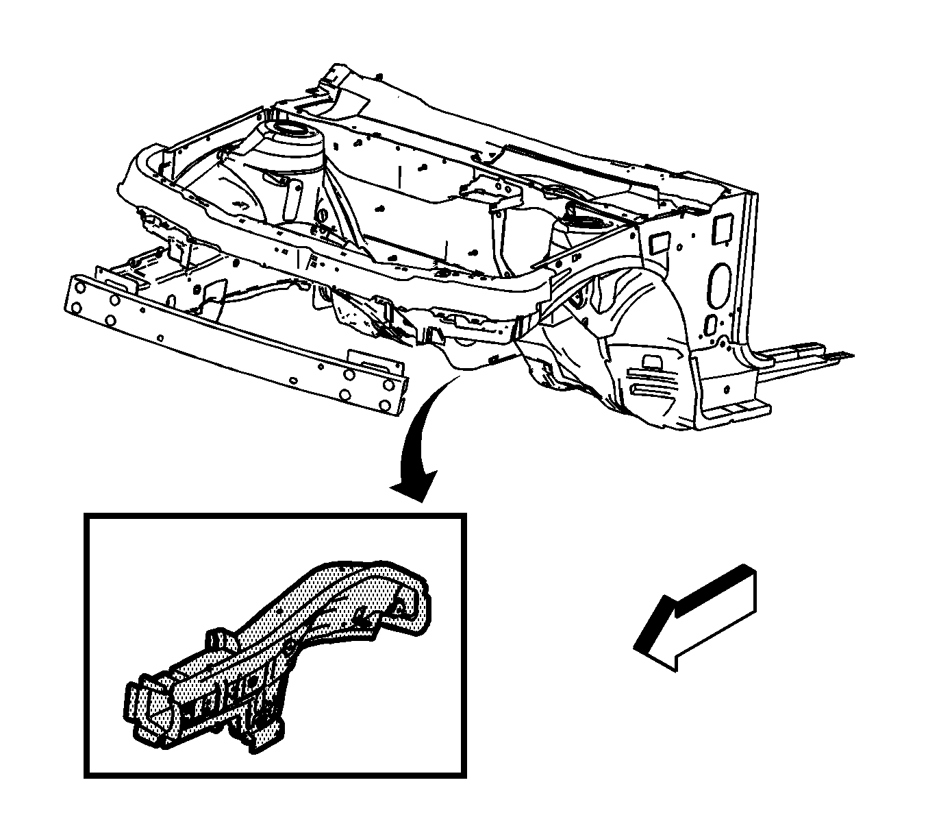
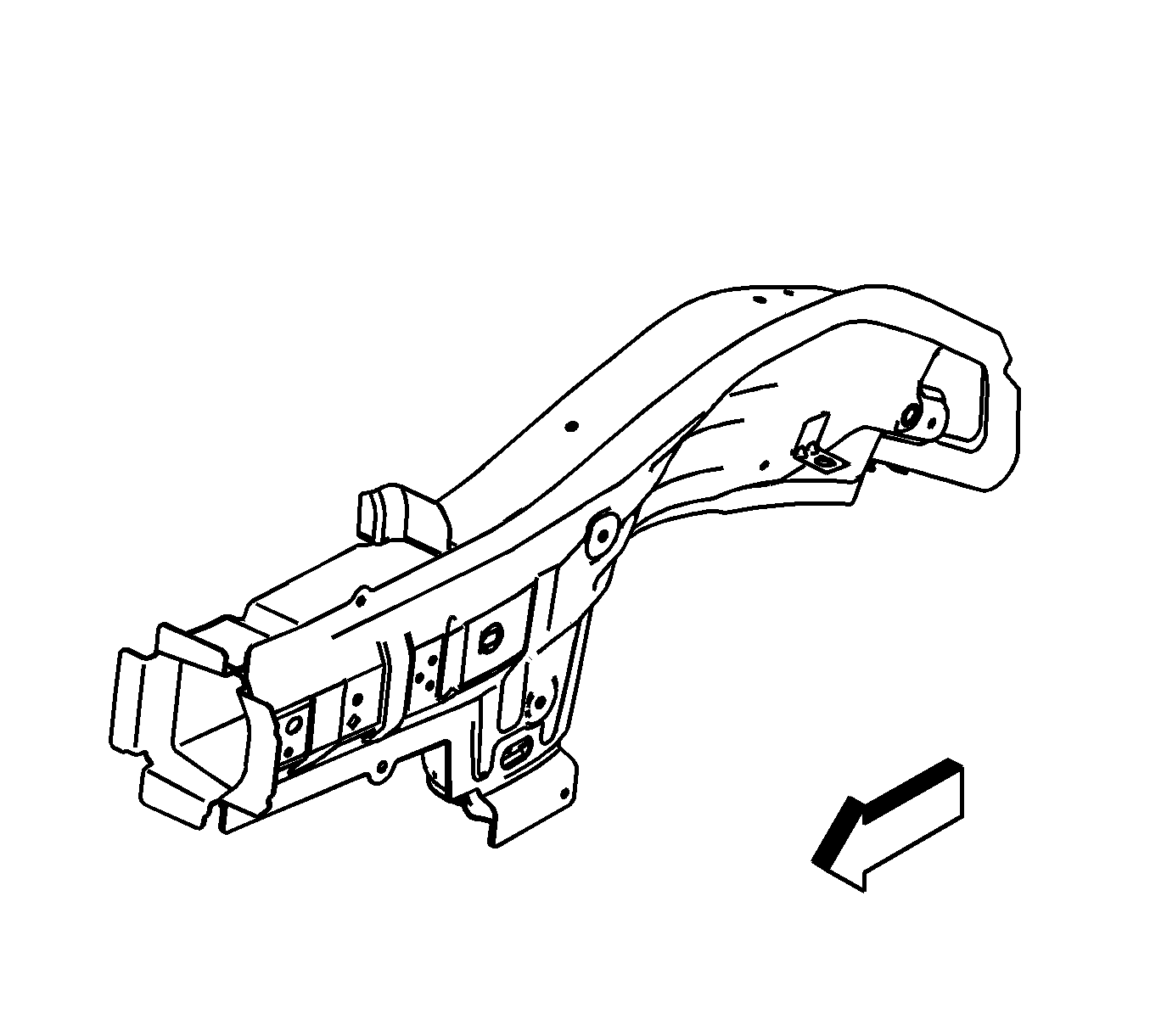
Note: The service part is developed from a complete assembly and will require the spot weld removal at the rail mid joint. The lower rail service part comes as a complete front rail assembly, including all the brackets and the reinforcements.
- Support the engine and the transmission with suitable equipment.
- Remove the fasteners to the engine and the transmission.
- Remove all the other related panels and components as necessary, including the suspension and the crossmember.
- Visually inspect the damaged area. Repair as much of the damage as possible to factory specifications. Refer to Dimensions - Body.
- Remove the sealers and anti-corrosion materials from the repair area, as necessary. Refer to Anti-Corrosion Treatment and Repair.
- Locate the area where the front compartment will be separated from the rail.
- Locate and drill the factory welds along the flanges of the rail, only up to and including the rail mid joint just forward of the dash panel.
- Drill out the factory welds.
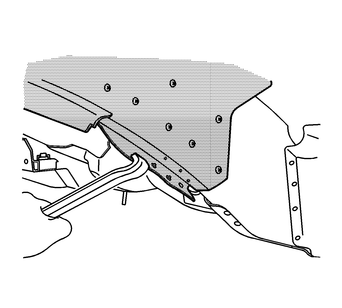
- Pry open the outer layer of the rail at the front rail mid joint to allow the front portion of the rail to be removed from the vehicle.
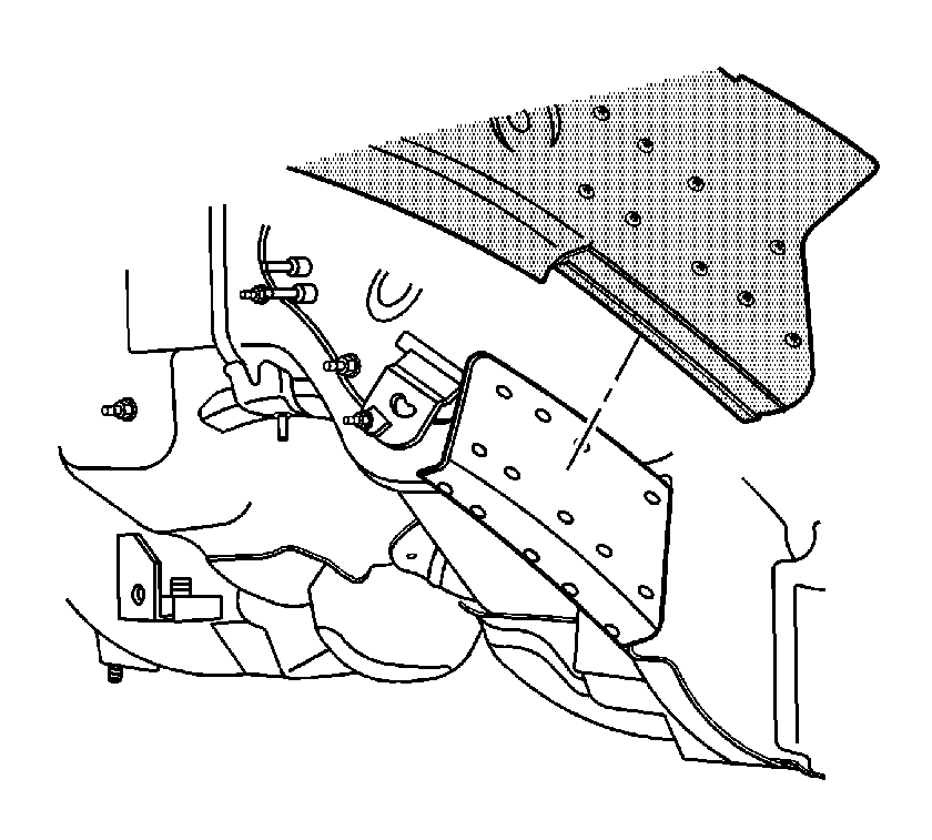
- Remove the damaged front lower rail.
- Drill out the factory welds at the service rail assembly mid joint.
- Remove the forward portion of the front rail assembly at the mid joint.
- Prepare the mating surfaces as necessary.
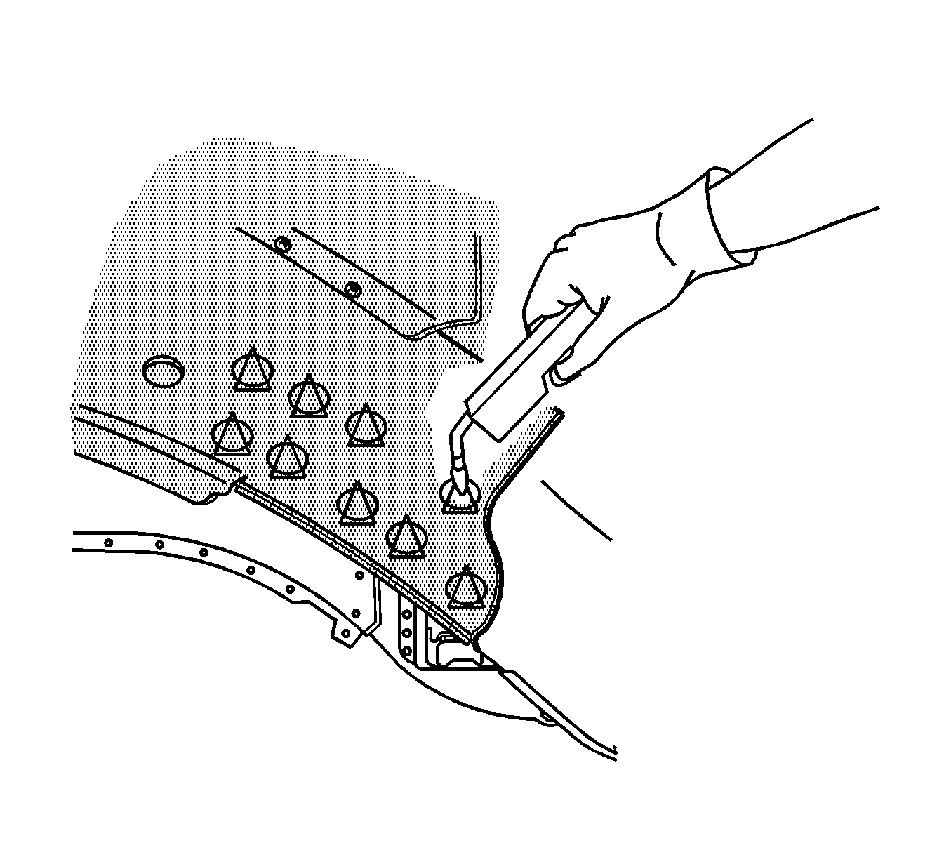
- Apply GM-approved Weld-Thru Coating or equivalent to all mating surfaces. Refer to Anti-Corrosion Treatment and Repair.
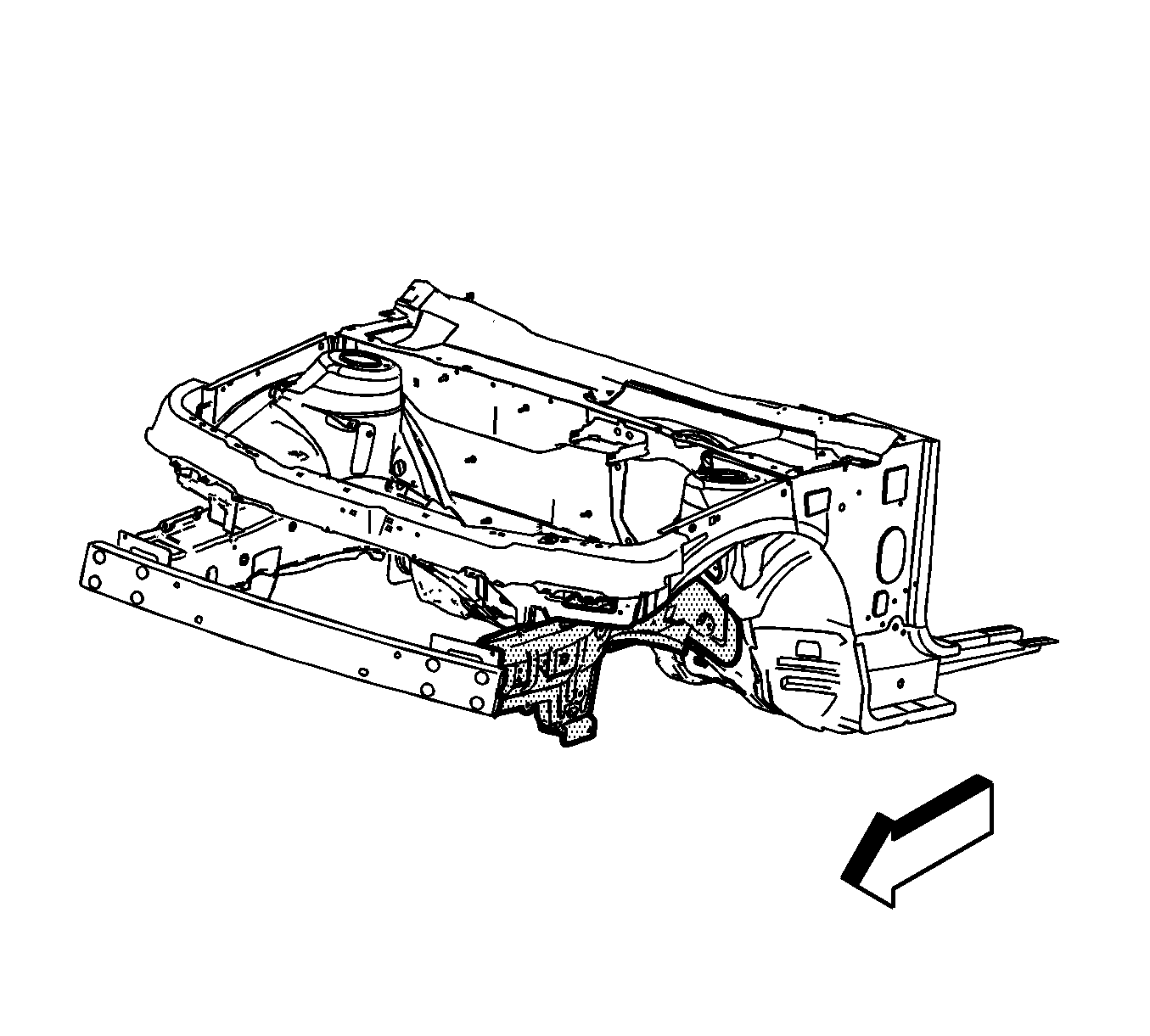
Note: Loosen and protect the fuel and brake lines during rail replacement.


Installation Procedure
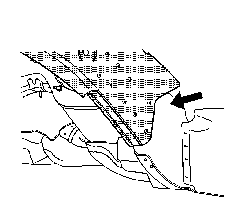
- Drill 8 mm (5/16 in) plug weld holes in the service part as necessary in the locations noted from the original panel.
- Prepare all mating surfaces as necessary.
- Apply GM-approved Weld-Thru Coating or equivalent to all mating surfaces. Refer to Anti-Corrosion Treatment and Repair.
- Position the rail to the vehicle.
- Plug weld accordingly.
- Clean and prepare all of the welded surfaces.
- Install all related panels and components.
- Apply sealers and anti-corrosion materials to the repair area, as necessary. Refer to Anti-Corrosion Treatment and Repair.
- Install the suspension crossmember. Refer to Frame Replacement.

Note: If the location of the original plug weld holes can not be determined, space the plug weld holes every 40 mm (1½ in) apart.
