Malfunction Indicator Lamp On - Check Engine Light - keywords 2.5 2.5L 6T40 ABS B0268 C0561 display DTC erratic gage gauge HVAC instrument inoperative IPC LE5 MH8 MIL no panel P0700 P150C P2544 SES

| Subject: | Malfunction Indicator Lamp On -- Check Engine Light |
| Models: | 2008-2009 Chevrolet Malibu |
| 2009 Pontiac G6 |
| 2009 Saturn Aura |
| Equipped with 2.5L Engine (VIN Code B -- RPO LE5) and 6T40 Automatic Transaxle (RPO MH8) |
The following diagnosis might be helpful if the vehicle exhibits the symptom(s) described in this PI.
Condition/Concern:
Some customers may comment on one or more of the following concerns:
| • | Check engine light is illuminated |
| • | Engine cranks but does not start |
| • | Harsh transmission shifts |
| • | No transmission shifts |
| • | Instrument cluster operation erratic or inoperative |
A scan tool may reveal some or all of the following DTCs: P150C, U0073, U0100 or U2106.
Recommendation/Instructions:
Inspect harness for chaffed wires perform High speed LAN diagnostics to determine cause. Install inline Cooling fan jumper harnesses with built-in voltage suppression following the procedure outlined below.
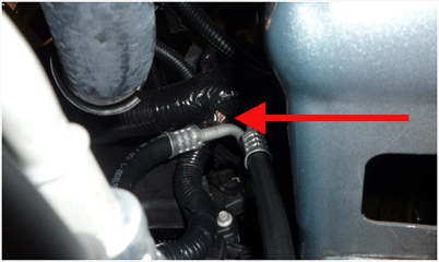
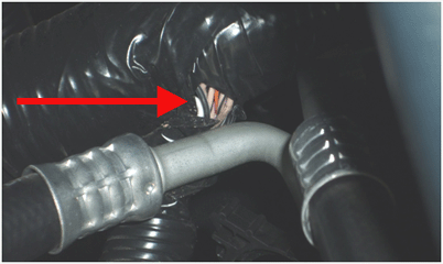
Harness Chafe
- Inspect wiring Harness for chafes in the area shown.
- Correct any issue found and tie strap harness back from rub points.


Test High speed LAN
Follow PIC4957: HIGH SPEED LAN Diagnostics to diagnose the system for identification of other possible wiring or module issues causing High Speed LAN communication issues.
Install inline Cooling fan jumper harnesses.
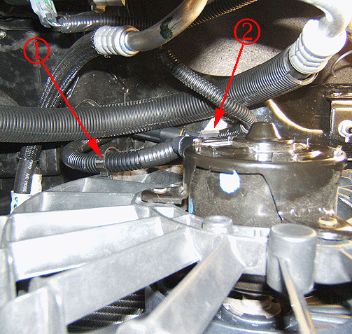
Disconnect the left cooling fan electrical connector. Remove wiring harness clip from the fan shroud. Connect the engine cooling fan jumper harness to the fan connection. Secure the jumper harness to the fan shroud (location 2) using clip. Secure the existing wiring harness clip to the fan shroud upper hole (location 1).


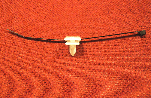
Disconnect the right cooling fan electrical connector. Remove wiring harness clip from the fan shroud. Connect the engine cooling fan jumper harness to the fan connection. Secure the jumper harness to the fan shroud (location 1) using clip. Install a tie strap through retainer, GM P/N 22603384 as shown and install retainer into existing hole in the frame (location 2). Secure the harness to the retainer using tie strap.
Part Number | Description | Qty |
|---|---|---|
15242642 | Harness, Engine Cooling Fan | 2 |
22603384 | Retainer | 1 |
Please follow this diagnostic or repair process thoroughly and complete each step. If the condition exhibited is resolved without completing every step, the remaining steps do not need to be performed.
