Removal Procedure
Important: It is essential to comply with the instructions for the hydraulic modulator and the ABS control unit. Refer to
ABS Control Unit General Repair Specification.
- Remove the cover of the brake fluid reservoir.
- Siphon out as much brake fluid as possible with a siphon bottle.
- Remove the battery.
| 3.1. | Remove the ground connection nut and remove the terminal from the battery. |
| 3.2. | Remove the positive connection nut and remove the positive terminal from the battery. |
| 3.3. | If present, remove the thermal protection (battery jacket). |
| 3.4. | Remove the bracket that holds the battery. |
Remove the bolt. Use a magnetic nut to prevent the bolt from falling into the engine compartment.

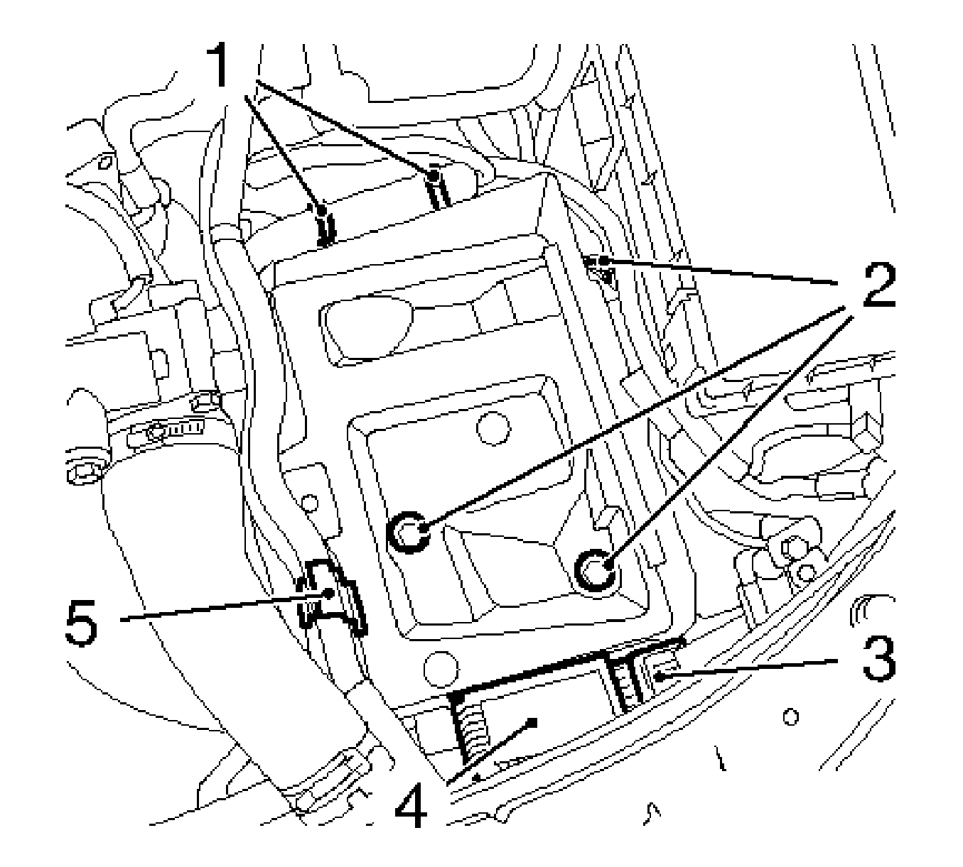
- Remove the battery support.
Remove the 3 bolts (2).
Important: Cooling system remains sealed.
- Remove the coolant surge tank.
| 5.1. | Remove the securing clip of the surge tank. Use a hook and pull the clip to the front of the vehicle. |
| 5.2. | Disconnect the wiring harness plug, below the surge tank, from the coolant level sensor. |
| 5.3. | Pull the coolant surge tank to the front of the vehicle and set the coolant surge tank aside. |

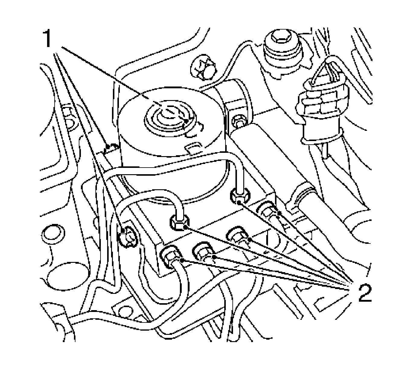
- Remove the hydraulic modulator.
| 6.1. | Disconnect the hydraulic modulator wiring harness plug. |
| 6.2. | Remove the 6 hydraulic lines (2). |
| 6.3. | Install the 6 sealing plugs on the hydraulic modulator. |
| 6.4. | Remove the 3 bolts (1). |
Installation Procedure
Notice: Refer to Fastener Notice in the Preface section.
- Install the hydraulic modulator.
Tighten
Tighten the 3 hydraulic modulator bolts to 8 N·m (71 lb in).
| 1.1. | Remove the 6 sealing plugs from the hydraulic modulator. |
| 1.2. | Install the 6 hydraulic lines. |
Tighten
Tighten the 6 hydraulic lines retaining bolts to 14 N·m (124 lb in).
| 1.3. | Connect the hydraulic modulator wiring harness plug. |
- Install the coolant surge tank to the mounting.
Connect the wiring harness plug for the coolant level sensor.
- Install the battery support.
Tighten
Tighten the 3 battery support bolts to 10 N·m (89 lb in).
| 3.1. | Install the wiring harness plug. |
| 3.2. | Install the coolant hose at the battery tray. |
| 3.3. | Install the wiring harness. |
Install the 2 cable ties.
- Install the battery.
| 4.1. | Install the battery bracket. |
Tighten
Tighten the battery bracket bolt to 15 N·m (11 lb ft).
| 4.2. | If present, install the thermal protection. |
| 4.3. | Install the battery positive connection to the positive terminal. |
Tighten
Tighten the battery positive connection nut to 5 N·m (44 lb in).
| 4.4. | Install the battery ground connection to the ground terminal. |
Tighten
Tighten the battery ground connection nut to 5 N·m (44 lb in).
- Bleed the brake system. Refer to
Hydraulic Brake System Bleeding.
- Top up the brake fluid reservoir to the MAX marking.
- Install the cover onto the brake fluid reservoir.
- For programming procedures, refer to
Control Module References.


