For 1990-2009 cars only
Special Tools
SA9164C /KM-J-22610 Clamp Pliers
Removal Procedure
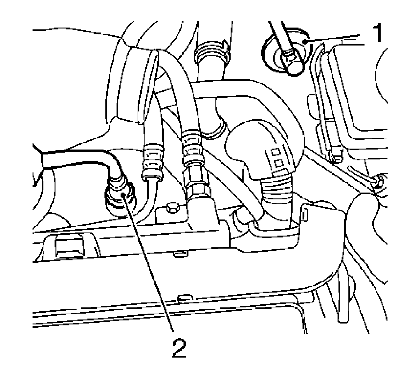
- Remove the vacuum line elbow (1) from the brake servo.
- Remove the snap fastening (2) for the vacuum line from the front intake manifold or from the vacuum pump.
- Remove the snap fastening by pressing in the latch.
- Remove the vacuum line.

Installation Procedure
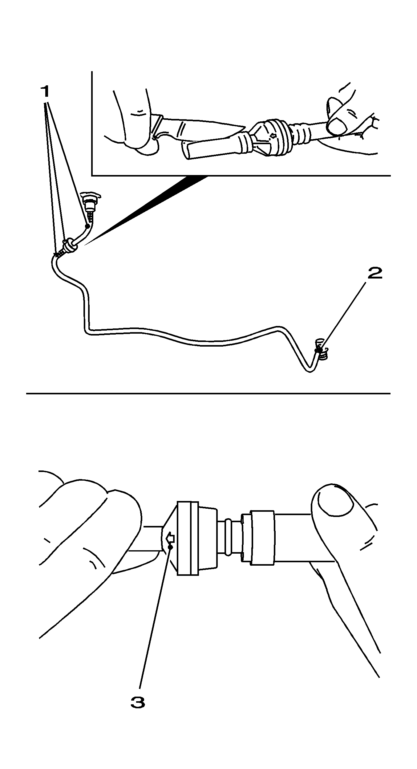
- Cut the open vacuum line at connections (1, 2) and remove from the connectors.
- Cut the new vacuum line (rubber hose with textile inlay) to length and fit with new clamps and SA9164C /KM-J-22610.
- Press the vacuum pressure lines with elbow into brake servo.
- Engage the vacuum line snap fastening onto connector of the intake manifold or the vacuum pump.
- Inspect the function of the brake servo. Refer to Brake Assist System Diagnosis .

Important: Ensure that the arrow (3) on the non-return valve points in the direction of the intake manifold or vacuum pump.
Important: Ensure that all the connections are perfectly sealed.
