Special Tools
KM-6001-A
Engine Mount
Removal Procedure
- Open the hood.
- Disconnect the battery.
| • | Remove the negative connection from the negative terminal. |
- Remove the battery.
| • | Remove the positive connection from the positive terminal. |
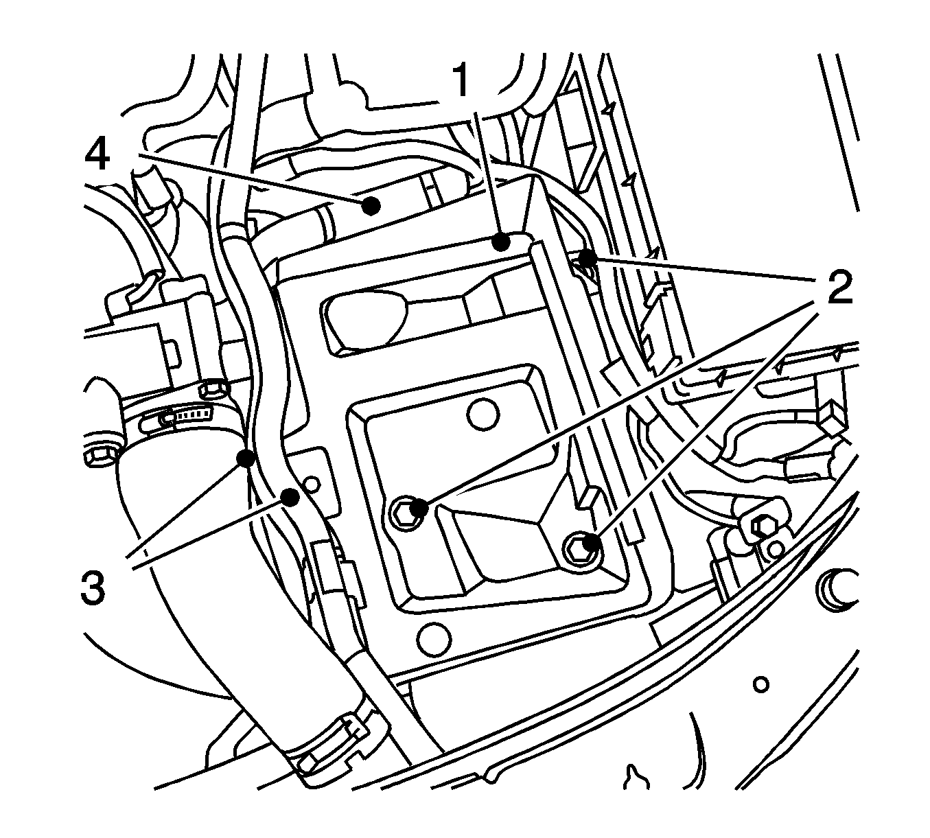
- Remove the battery support (1).
| • | Remove the 2 coolant hoses (3). |
| • | Remove the wiring harness (4) from the battery tray. |
| • | Remove the 2 cable ties. |
| • | Remove the 3 bolts (2). |
- Raise the vehicle by its full height.
- Remove the lower engine cover and the right engine splash shield.
Notice: Refer to Fastener Notice in the Preface section.
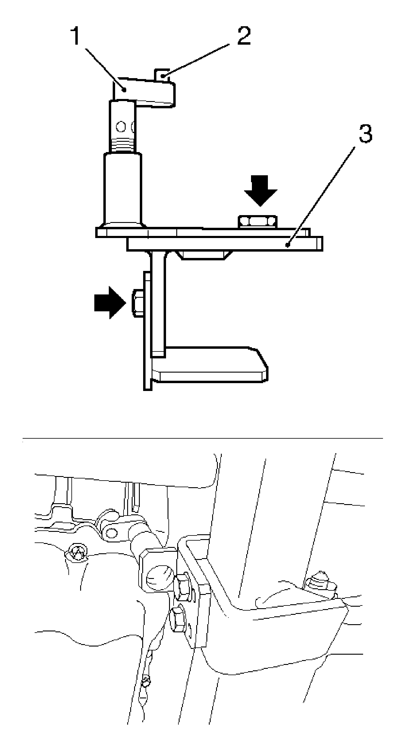
- Insert the KM-6173 (3)-Assembly.
| • | Loosen the 4 bolts (arrows) and hand-tighten. |
| • | Align KM-6173 at front axle body. |
| • | Position the support bearing (1). |
| • | The journal (2) must sit in the mount at the cylinder block. |
Tighten
Tighten the 4 bolts.
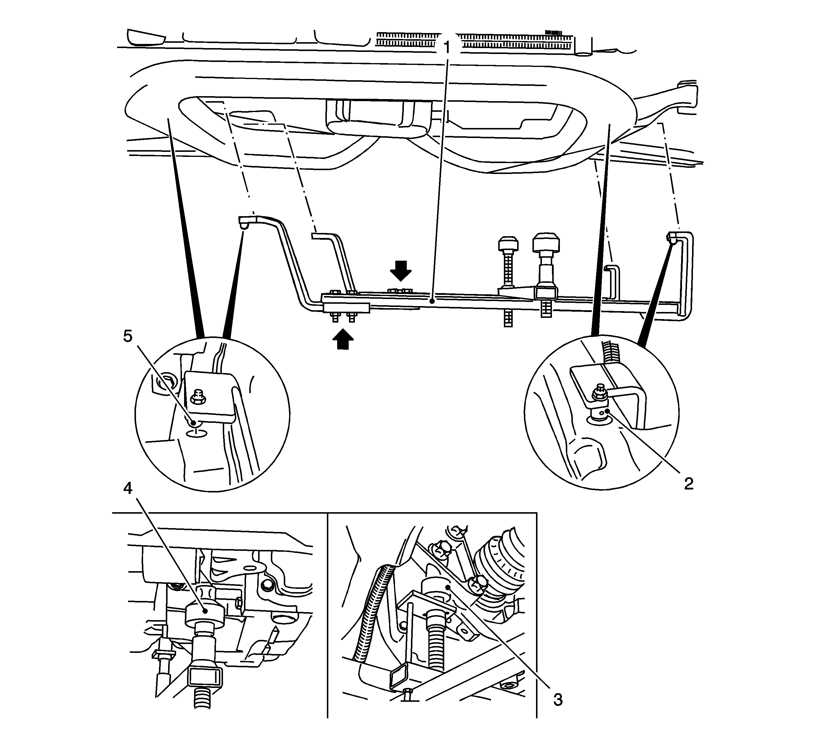
Important: Attaching
KM-6001-A
guarantees perfect alignment of the drive unit with the front axle body.
- Attach
KM-6001-A
(1).
| • | Loosen the 3 bolts (arrows) in the adjusting rails. |
| • | The journals (2, 5) must sit in the guide holes of the front axle body. |
Tighten
Tighten the 3 bolts in the adjusting rails.
| • | Adjust the support bearings, front (4) and rear (3). |
| | Important: The guide journals must be seated free from play in the support bearings.
|
| • | Raise the support bearings up to the stop on the guide journals. |
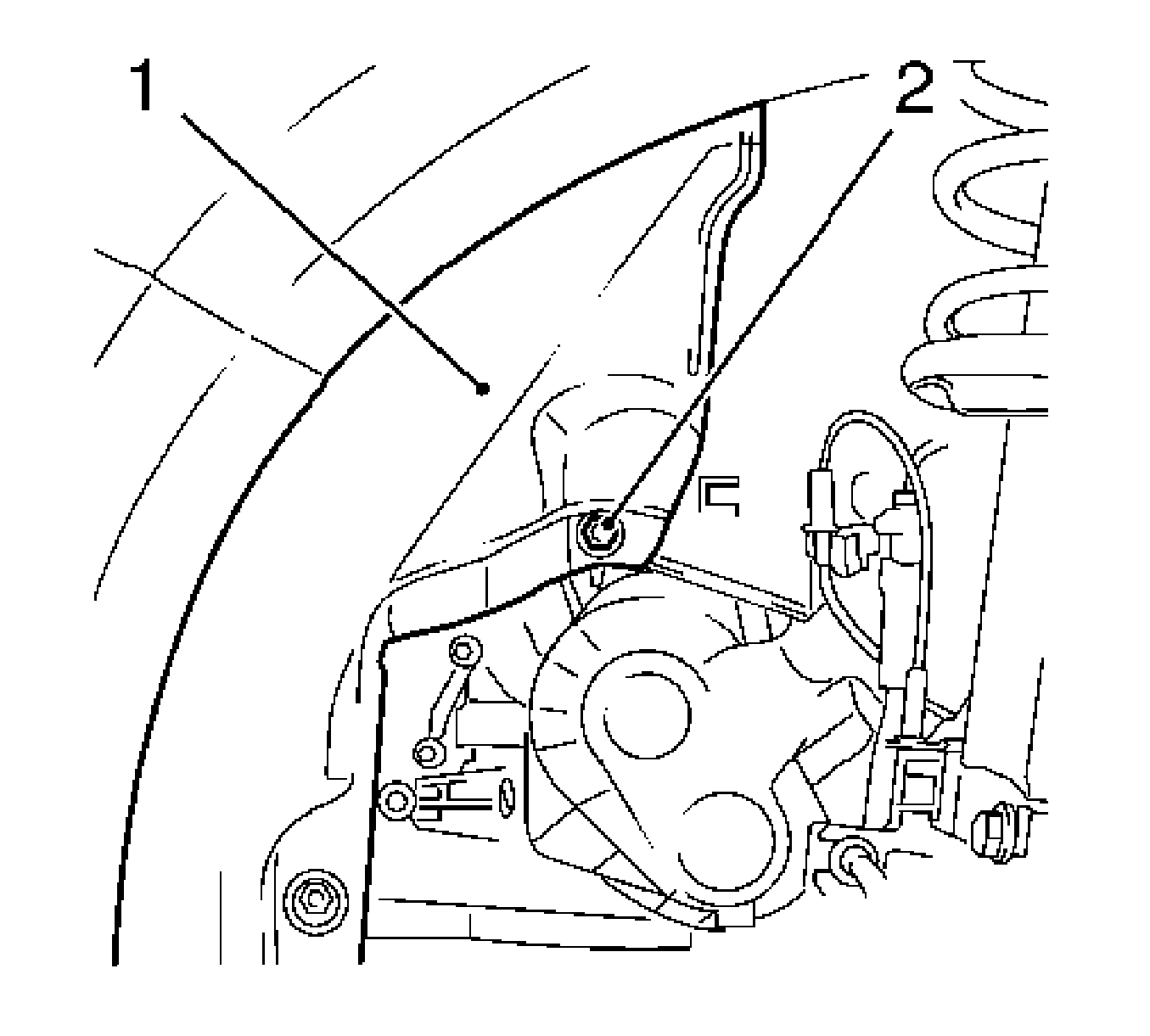
- Release the left wheel housing inner paneling (1).
Remove the body-bound rivet (2).
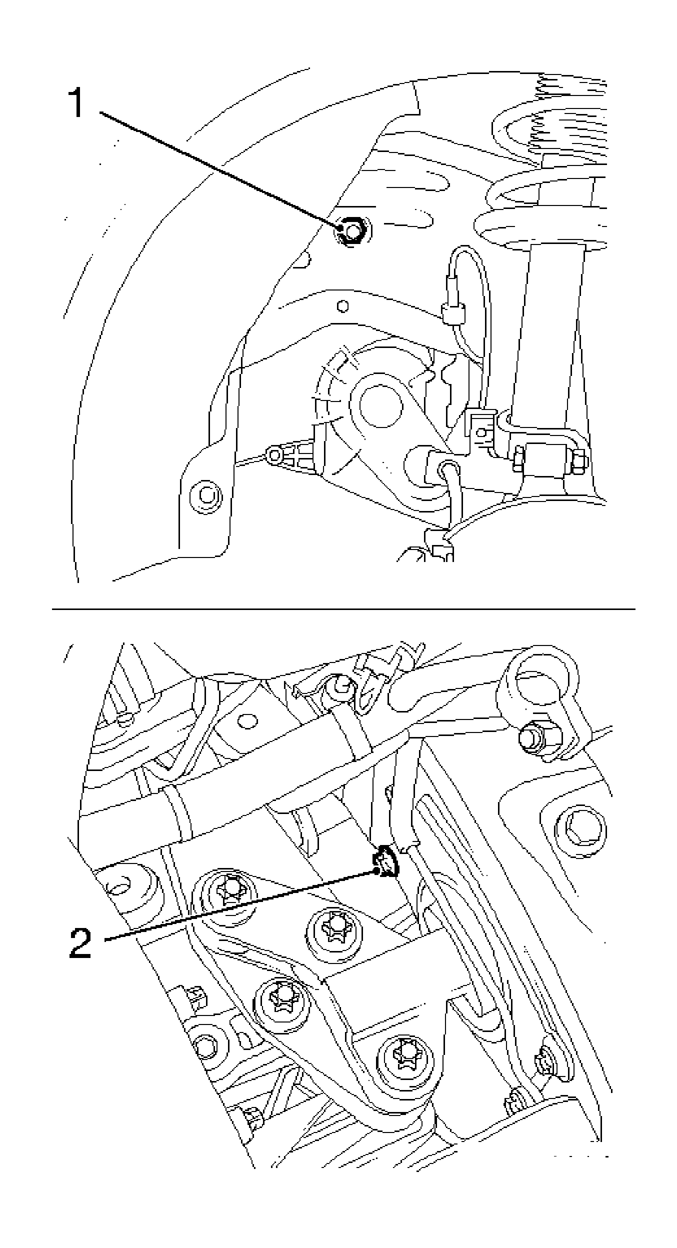
- Remove the engine mount from the side member.
- Lower the vehicle by its full height.
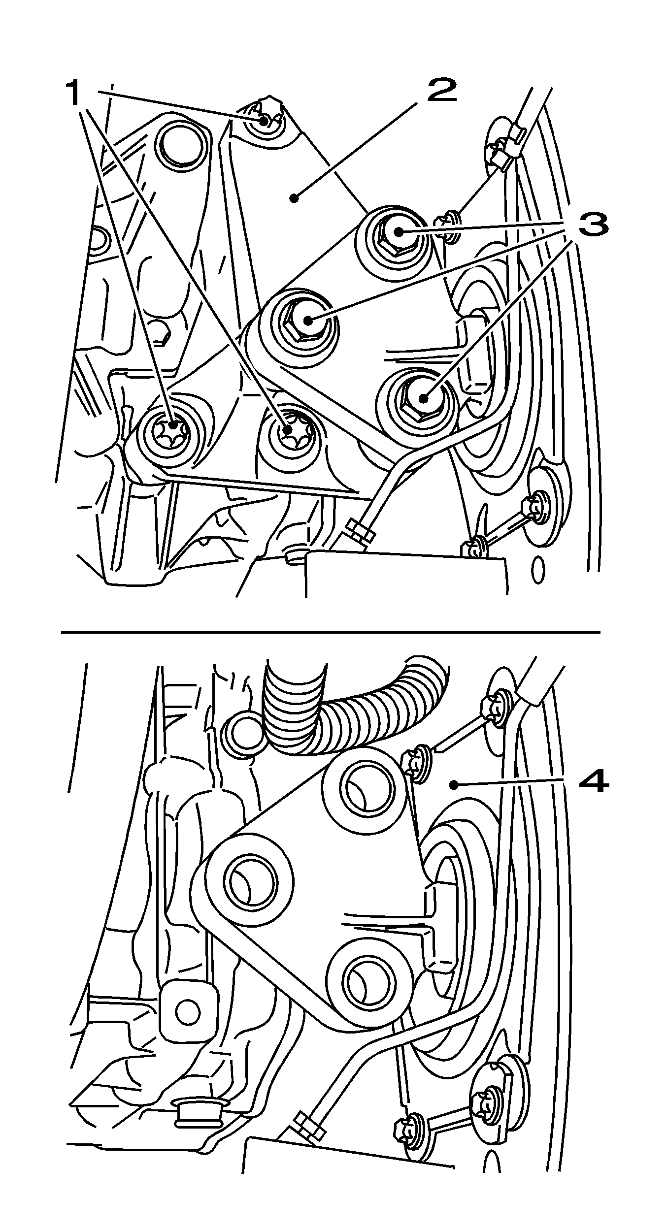
- Remove the left-hand engine mount support (2).
Remove the 6 bolts (1, 3).
- Remove the engine tray (4) with the bracket from the side member.
| • | Remove the clutch pressure line. |
| • | Release the 2 from the bracket. |
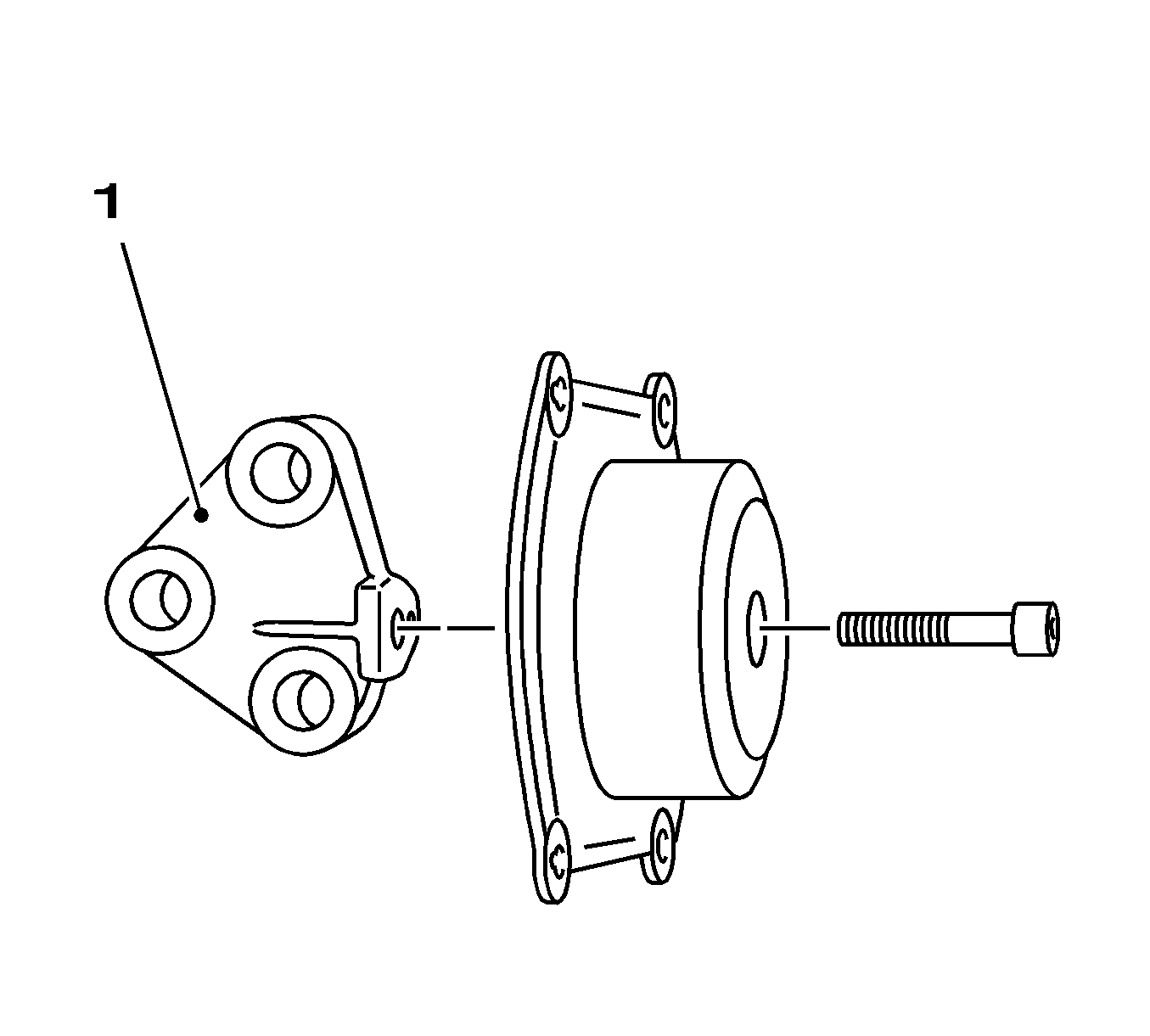
- Remove the engine mount bracket (1).
Installation Procedure
Notice: Refer to Fastener Notice in the Preface section.
- Install the bracket to the engine mount.
Tighten
Tighten the bolt to 55 N·m (40 lb ft).
- Remove the engine mount from the vice.
- Install the engine mount to the longitudinal beam.
Tighten
Tighten the 4 bolts to 55 N·m (40 lb ft).
| • | Install the clutch pressure line. |
| • | Install the 2x in bracket. |
- Install the left-hand engine mount support.
| • | Install the engine mount bracket to the transmission. |
Tighten
Tighten the 3 bolts to 35 N·m (26 lb ft).
| • | Install to the engine mount bracket. |
Tighten
Tighten the 3 bolts to 55 N·m (40 lb ft).
- Raise the vehicle by its full height.
- Install the engine mount to the longitudinal beam.
Tighten
| • | Tighten the bolt to 20 N·m (15 lb ft). |
| • | Tighten the nut to 20 N·m (15 lb ft). |
- Fasten the paneling, wheel housing.
Install the body-bound rivet.
- Remove the KM-6173 .
Remove the 4 bolts.
- Remove
KM-6001-A
.
Loosen the 3 screwed connections.
- Install the lower engine cover and the right engine splash shield.
- Lower the vehicle by its full height.
- Install the battery tray.
Tighten
Tighten the 3 bolts to 15 N·m (11 lb ft).
| • | Install the coolant hose bracket. |
| • | Install the 2 wiring harnesses. |
- Install the battery.
| • | Install the battery bracket. |
Tighten
Tighten the bolt to 5 N·m (44 lb in).
| • | Install the positive connection to the positive terminal. |
Tighten
Tighten the nut to 5 N·m (44 lb in).
- Connect the battery.
Install the negative connection to the negative terminal.
Tighten
Tighten the nut to 5 N·m (44 lb in).
- For programming procedures, refer to
Control Module References
.
- Close the hood.


