Removal Procedure
- Disconnect the battery.
- Remove the front doors. Refer to Front Side Door Replacement .
- Remove the instrument panel (I/P) padding. Refer to Instrument Panel Trim Panel Replacement - Right Side .
- Remove the passenger airbag. Refer to Inflatable Restraint Instrument Panel Module Replacement .
- Remove the steering column support tube. Refer to Steering Column Replacement .
- Remove the fan motor series resistor wiring harness plug (3).
- Remove the clutch pedal bearing support from the steering crossmember.
- Remove the brake pedal bearing support from the steering crossmember.
- Remove the wiring harness from the steering crossmember.
- Disengage and disconnect the brake pedal and accelerator pedal wiring harness plugs.
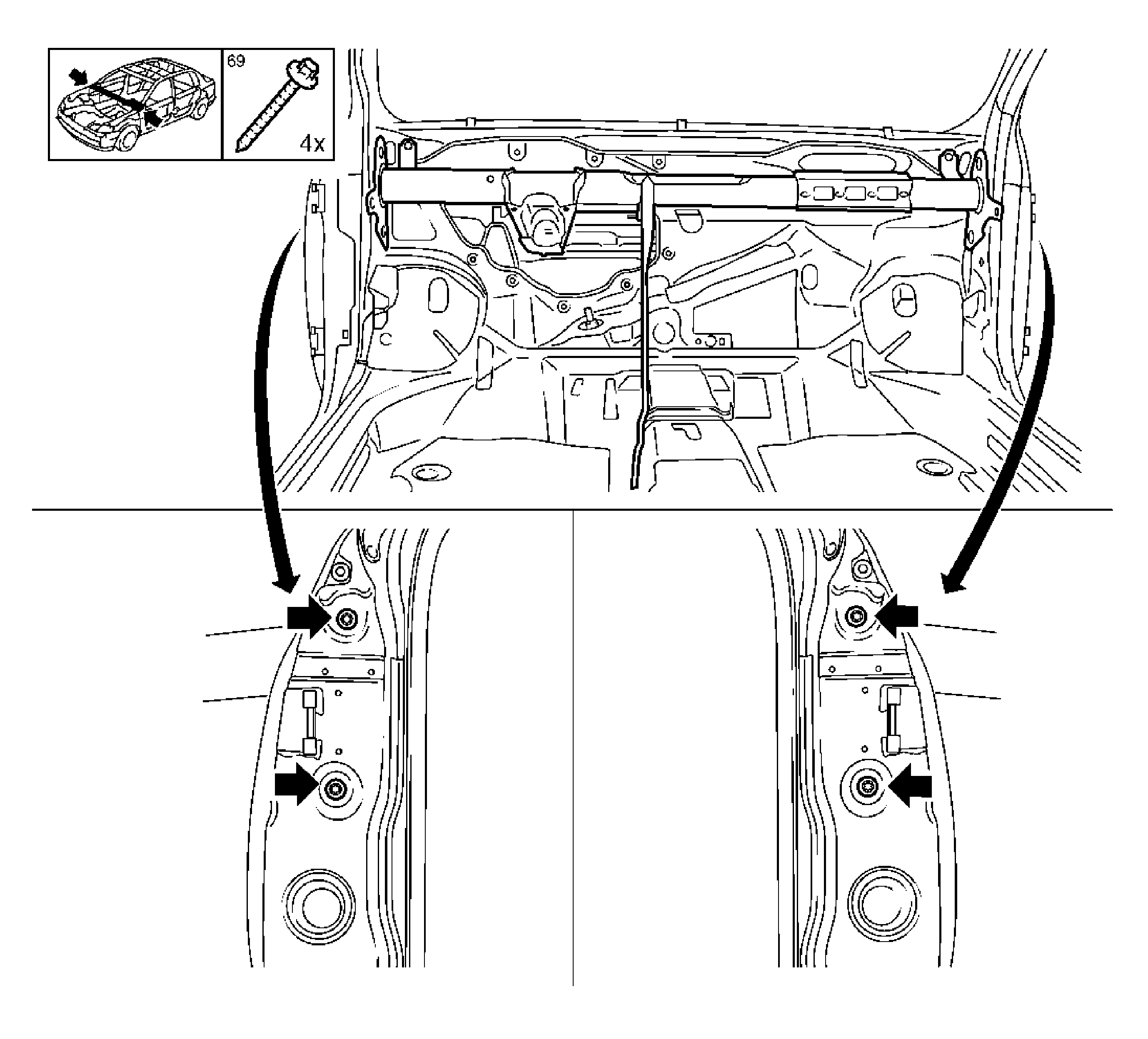
- Remove the I/P tie bar center bracket.
- Remove the I/P tie bar.
Caution: Refer to Battery Disconnect Caution in the Preface section.
Important: Disconnect the battery and wait 1 minute for the capacitor to discharge. Refer to SIR Disabling and Enabling .
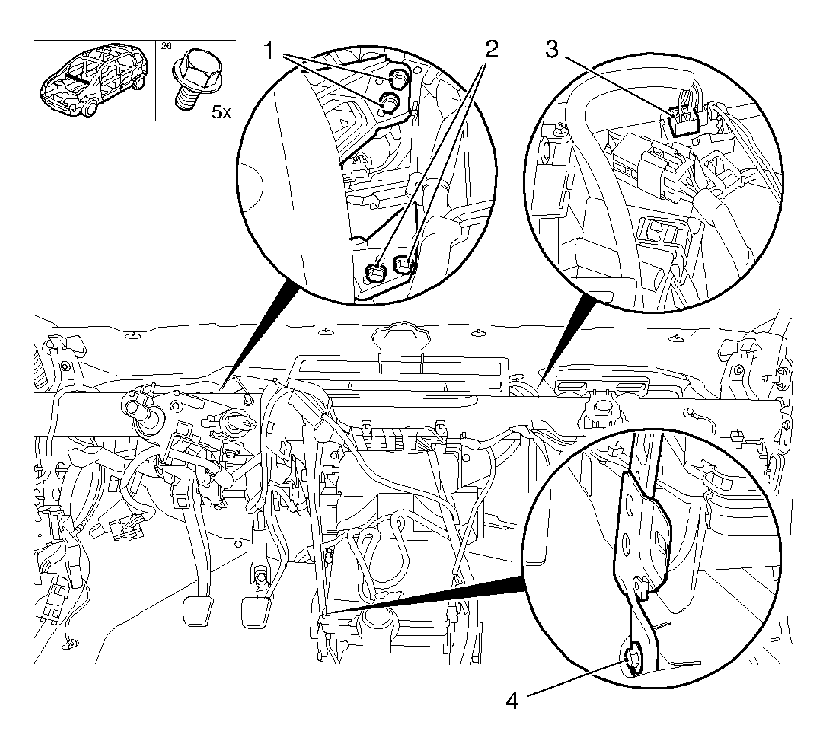
Remove the 2 bolts (2).
Remove the 2 bolts (1).
| 9.1. | Remove the 3 ground cables. |
| 9.2. | Remove the 3 nuts. |
| 9.3. | Disconnect the wiring harness. |
Remove the clip.
Remove the bolt (4).
Important: Avoid damaging the interior.
Remove the 4 bolts (arrows).
Installation Procedure
- Install the I/P tie bar.
- Install the I/P tie bar center bracket.
- Install the brake pedal and accelerator pedal wiring harness plugs.
- Install the wiring harness to the I/P tie bar.
- Install the brake pedal bearing support on the I/P tie bar.
- Install the clutch pedal bearing support on the I/P tie bar.
- Connect the fan motor series resistor wiring harness plug.
- Install the steering column support tube. Refer to Steering Column Replacement .
- Install the passenger airbag. Refer to Inflatable Restraint Instrument Panel Module Replacement .
- Install the I/P padding. Refer to Instrument Panel Trim Panel Replacement - Right Side .
- Install the front doors. Refer to Front Side Door Replacement .
- Connect the battery.
- For reprogramming procedures, refer to Control Module References .
Notice: Refer to Fastener Notice in the Preface section.
Important:
• Avoid damaging the interior. • Use screw locking compound when inserting bolts.
Tighten
Tighten the 4 bolts to 20 N·m (15 lb ft).
Important: Use screw locking compound when inserting bolts.
Tighten
Tighten the bolt to 13 N·m (113 lb in).
Install the clip.
| • | Install the wiring harness. |
| • | Install the 3 ground cables. |
Tighten
Tighten the 3 nuts to 5 N·m (44 lb in).
Important: Use screw locking compound when inserting bolts.
Tighten
Tighten the 2 bolts to 20 N·m (15 lb ft).
Important: Use screw locking compound when inserting bolts.
Tighten
Tighten the 2 bolts to 20 N·m (15 lb ft).
