For 1990-2009 cars only
Removal Procedure
- Raise and support the vehicle. Refer to Lifting and Jacking the Vehicle .
- Remove the wheel. Refer to Tire and Wheel Removal and Installation .
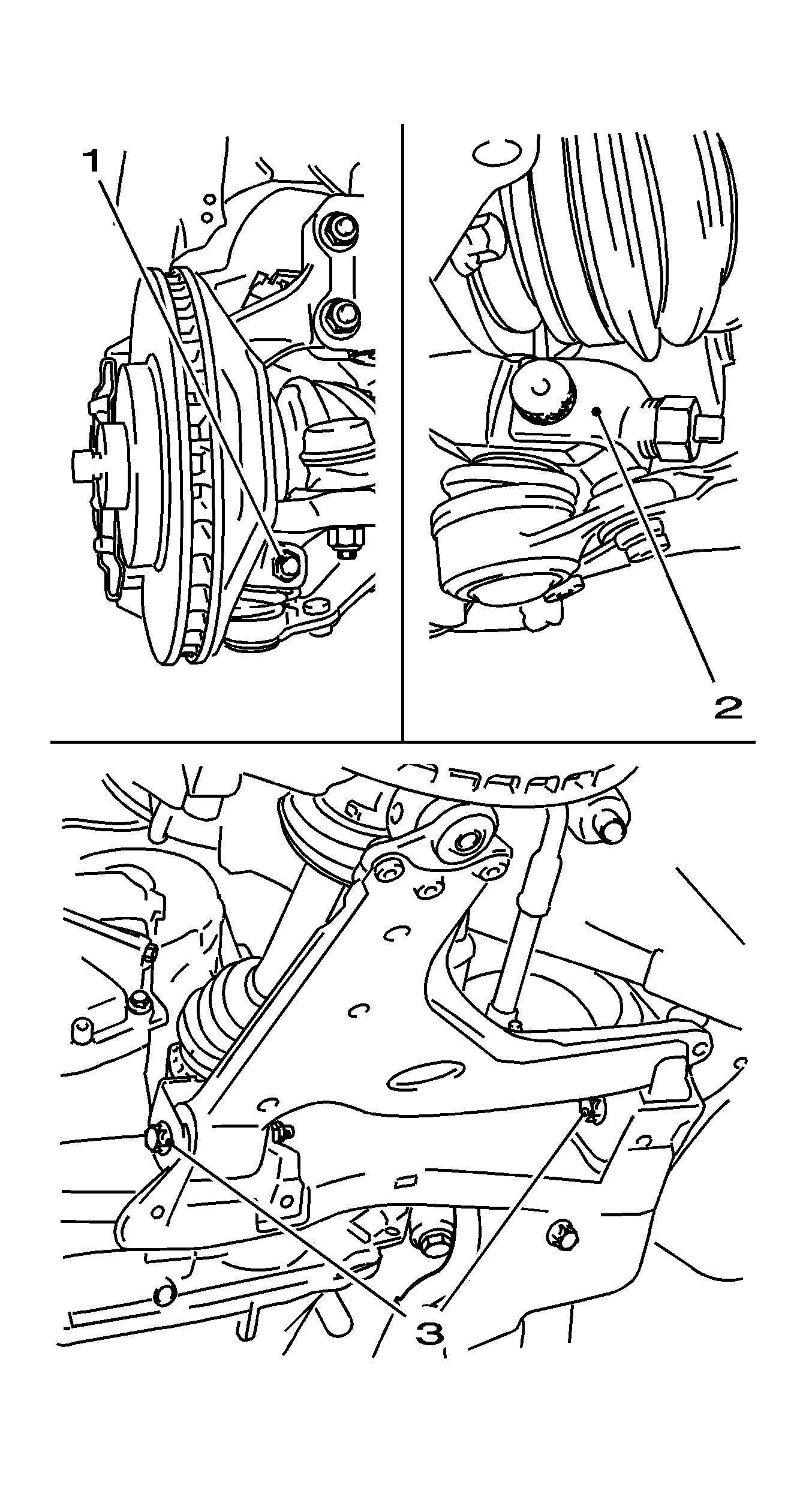
- Remove the ball stud to steering knuckle pinch bolt and nut (1).
- Separate the ball stud from the steering knuckle (2).
- Remove the lower control arm to frame bolts (3).
- Remove the lower control arm from the frame.

Notice: Do not pry in such a way that the ball joint seal is contacted. Damage to the seal may result.
Installation Procedure
- Install the lower control arm to the front frame.
- Install the lower control arm to the steering knuckle.
- Install the wheel. Refer to Tire and Wheel Removal and Installation .
- Lower the vehicle.
- Tighten the 2 bolted connections, lower control arm to the front frame. Refer to Trim Height Specifications .
- Road test the vehicle in order to test for leads or pulls. Refer to Wheel Alignment Specifications .
Important: Only tighten bolted connection loosely. The bolted lower control arm connection to the front frame is tightened at vehicle trim height.
| • | Install the 2 new bolts. |
| • | Install the 2 new nuts. |
Notice: Refer to Fastener Notice in the Preface section.
| • | Insert the guide joint into the steering knuckle. |
| • | Install the bolted connection. |
| • | Use NEW nuts. |
Tighten
Tighten to 50 N·m (37 lb ft).
Important: The vehicle must be standing on wheels, inspection stand or pit.
Load both front seats with 70 kg (154 lb).
Tighten
Tighten the 2 new screw connections for the lower control arm on front frame 90 N·m (67 lb ft) plus 75 degrees, plus 15 degrees.
