For 1990-2009 cars only
Special Tools
| • | KM-6351 Assembly Sleeves |
| • | KM-J-45000 Remover |
Removal Procedure
- Remove the exhaust manifold. Refer to Exhaust Manifold Replacement.
- Remove the oil pan. Refer to Oil Pan Replacement.
- Remove the generator. Refer to Generator Replacement.
- Remove the engine damping block, right side. Refer to Engine Mount Replacement - Right Side.
- Remove the engine damping block support from the cylinder block.
- Remove the drive belt. Refer to Drive Belt Replacement.
- Drain the coolant.
- Remove the drive belt tensioner (1).
- Raise the vehicle by its full height.
- Remove the coolant hose from the coolant pump.
- Detach the coolant pipe (2) from the pump module.
- Detach the coolant pipe (3) from the pump module.
- Remove the toothed belt drive gear.
- Remove the pump module.
- Replace the 4 coolant pipe seal rings.
- Clean the sealing surface.
- Remove the crankshaft seal ring (front) with KM-J-45000 .
- Remove the oil pump cover (1).
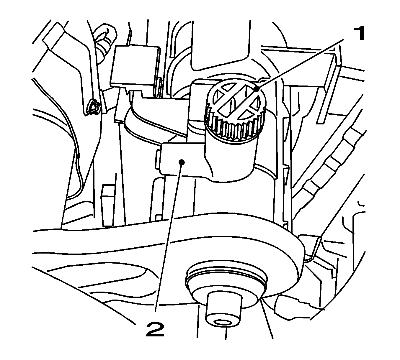
Remove the 3 bolts.
| • | Place a drip pan underneath. |
| • | Install the suitable hose to drain port. |
| • | Open the coolant drain screw (1). |
| • | Drain the coolant. |
| • | Close the coolant drain screw. |
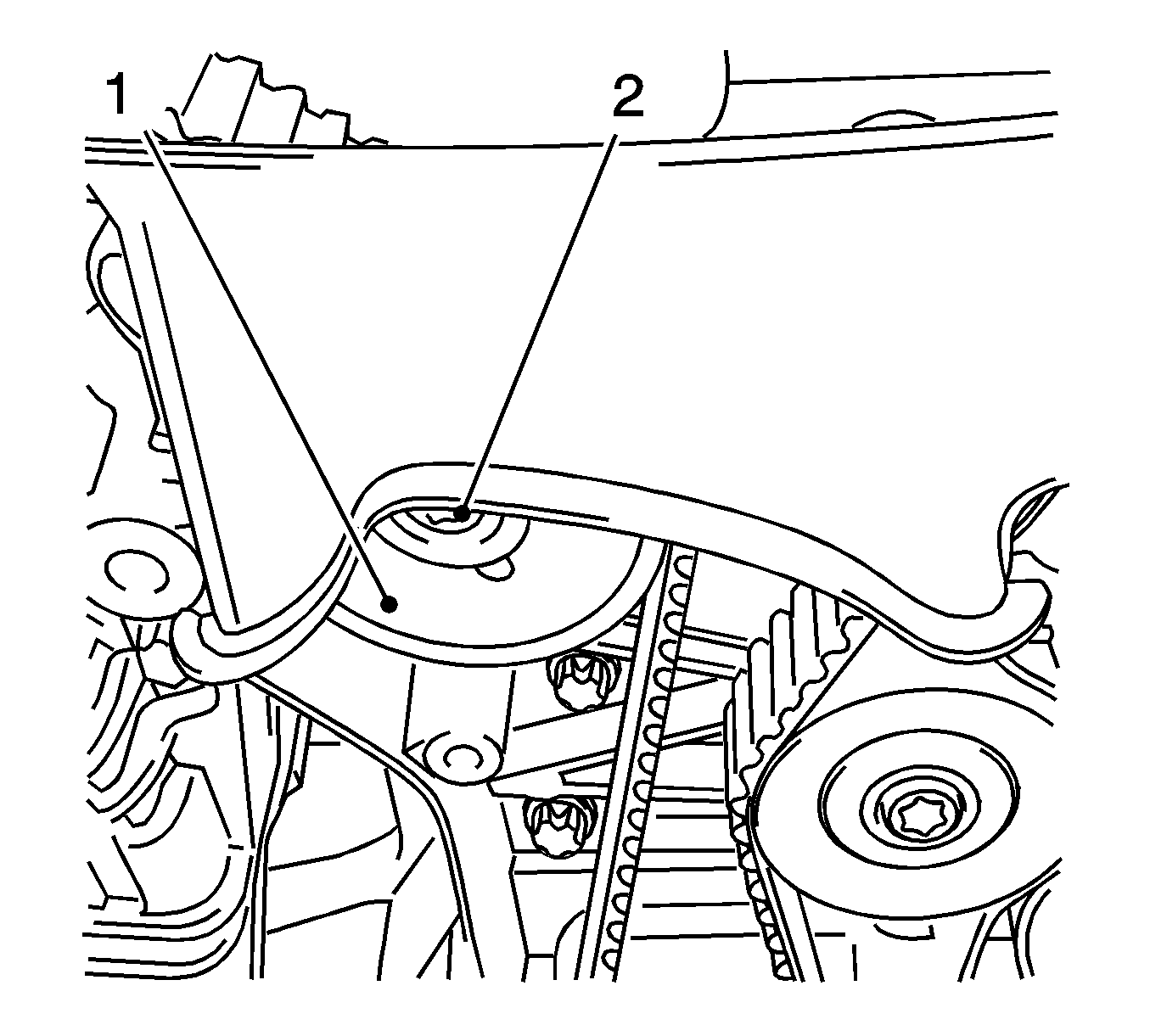
Remove the bolt (2).
Release the clamp.
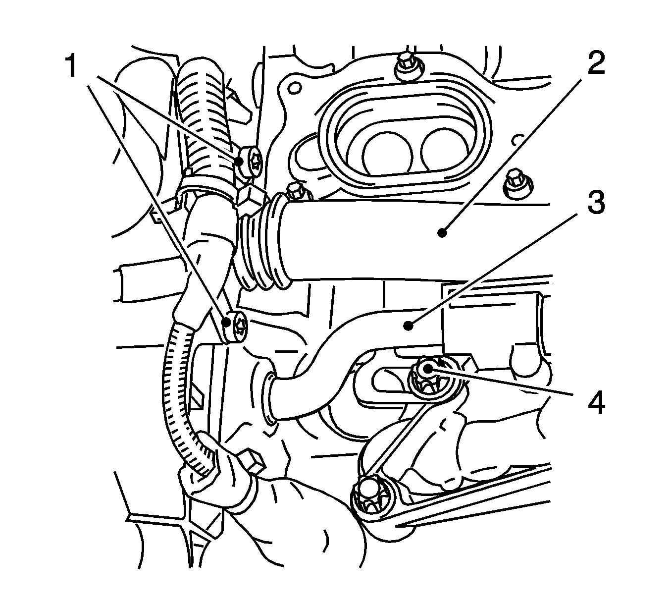
| • | Remove the 2 bolts (1). |
| • | Push the coolant pipe into the oil pump housing adapter. |
| • | Detach the coolant pipe from the oil filter housing adapter. |
| • | Remove the bolt (4). |
| • | Push the coolant pipe into the oil filter housing adapter. |
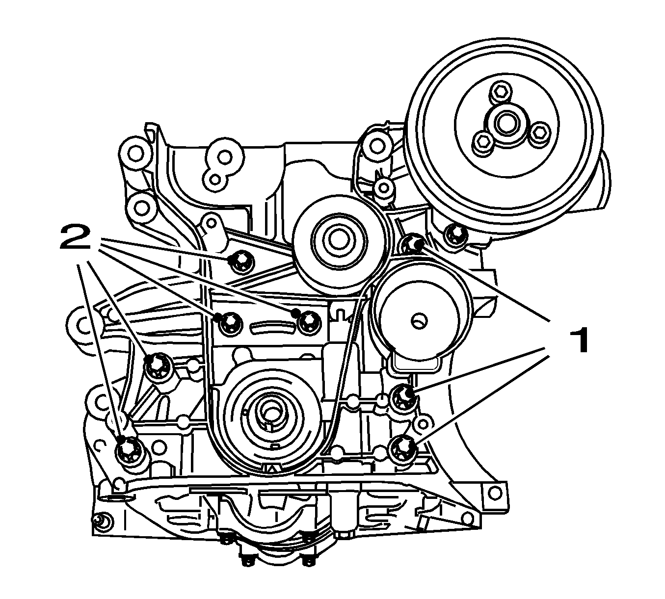
Note: Note different screw lengths.
| • | Remove the 8 bolts (1, 2). |
| • | Remove the gasket. |
| • | Remove the 2 coolant pipes from the oil filter housing adapter. |
| • | Insert the 2 coolant pipes in the oil filter housing adapter. |
Note: Do not damage the sealing surfaces.
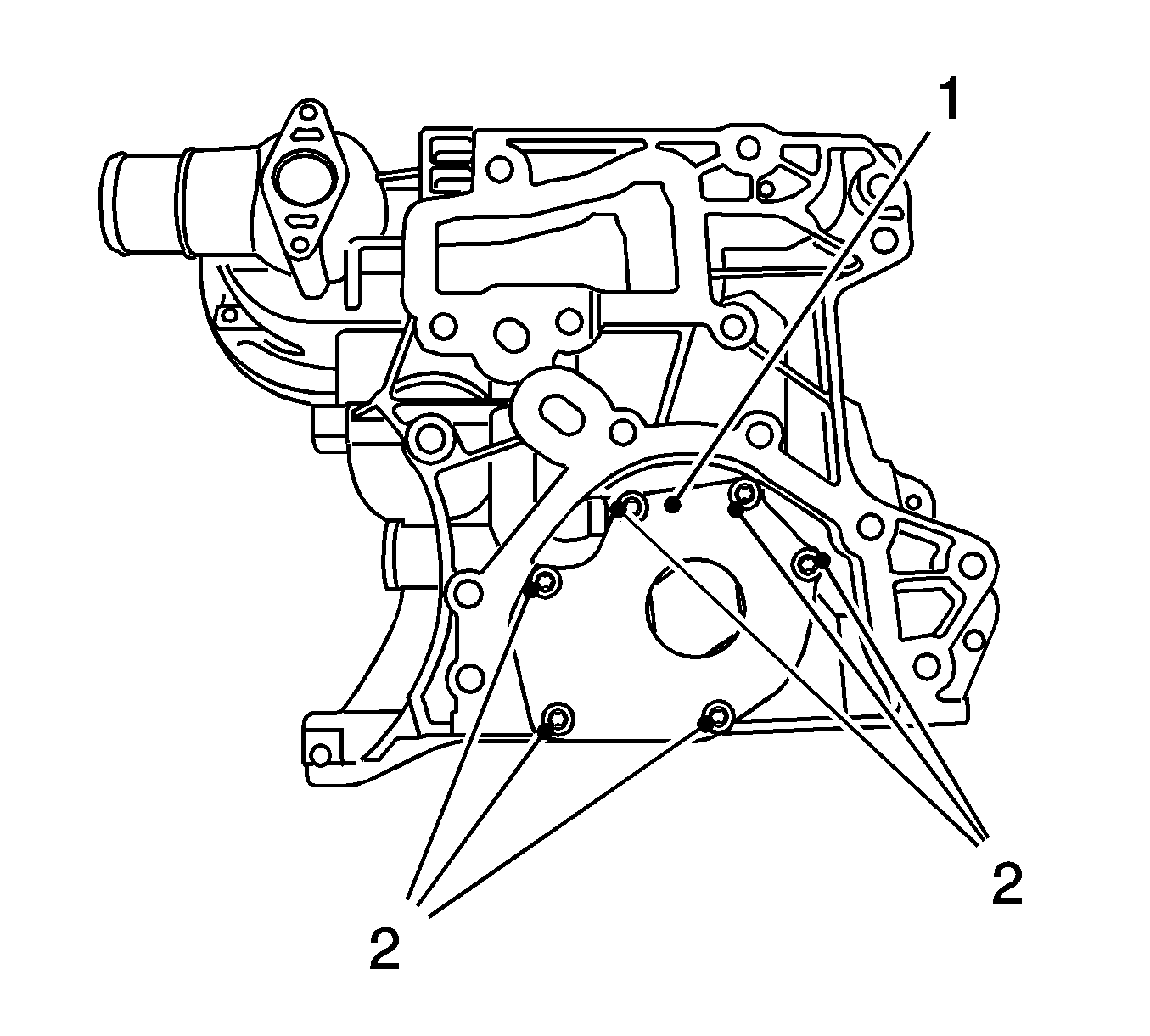
Remove the 6 bolts (2).
Inspection Procedure
- Visually inspect the components.
- Inspect the axial clearance of the rotors.
Remove the external rotor with the internal rotor.
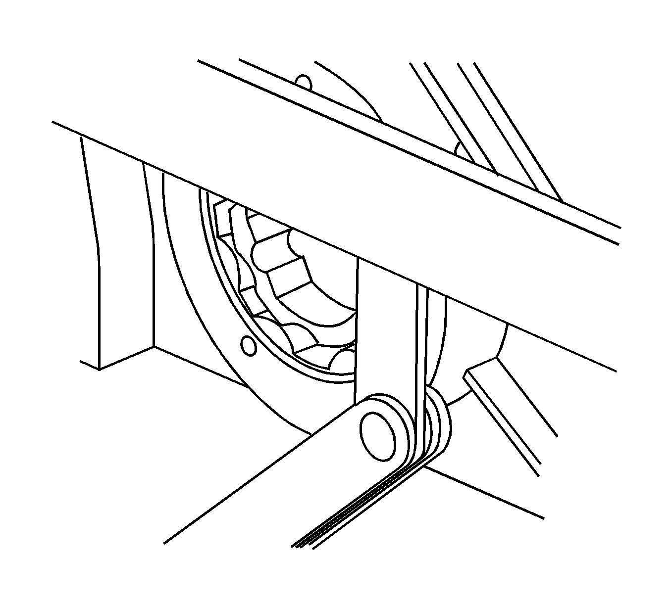
| • | Install the external and the internal rotors. |
| • | Inspect the axial clearance, rotors in respect of the upper edge of the control unit housing. |
| • | Permissible measurement: 0.02-0.058 mm. |
Installation Procedure
- Clean the sealing surface.
- Install the oil pump cover.
- Install the pump module.
- Install the coolant pipe to the coolant module.
- Install the coolant pipe to the coolant module.
- Install the front crankshaft seal ring (1).
- Clean the thread, drive belt tensioner.
- Intake the drive belt tensioner.
- Lower the vehicle by its full height.
- Install the drive belt. Refer to Drive Belt Replacement.
- Install the support for the engine damping block.
- Install the right engine damping block. Refer to Engine Mount Replacement - Right Side.
- Install the oil pan. Refer to Oil Pan Replacement.
- Install the generator. Refer to Generator Replacement.
- Connect the battery.
- Fill and bleed the cooling system. Refer to Cooling System Draining and Filling.
- For programming procedures, refer to Control Module References.
- Close the hood.
Caution: Refer to Fastener Caution in the Preface section.
Tighten
Tighten the 6 bolts to 8 N·m (71 lb in).
Note: Note different screw lengths.
| • | Replace the gasket. |
| • | Tighten the 8 bolts. |
Tighten
Tighten the 8 bolts to 20 N·m (15 lb ft).
| • | Insert the toothed belt drive gear. |
| • | Pull the coolant pipe out of the oil filter housing adapter. |
| • | Install the coolant pipe to the oil filter housing adapter. |
Tighten
Tighten the bolt to 9 N·m (80 lb in).
Pull the coolant pipe out of the oil pump housing adapter.
Tighten
Tighten the 2 bolts to 9 N·m (80 lb in).
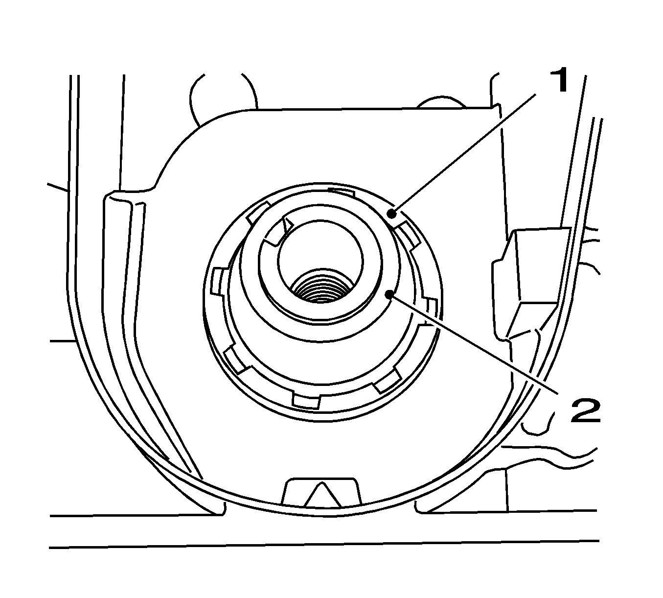
| • | Clean the sealing surfaces. |
| • | Slide the protective sleeve of KM-6351 (2) onto the crankshaft journal. |
| • | Slide the seal ring over the protective sleeve on the crankshaft journal. |
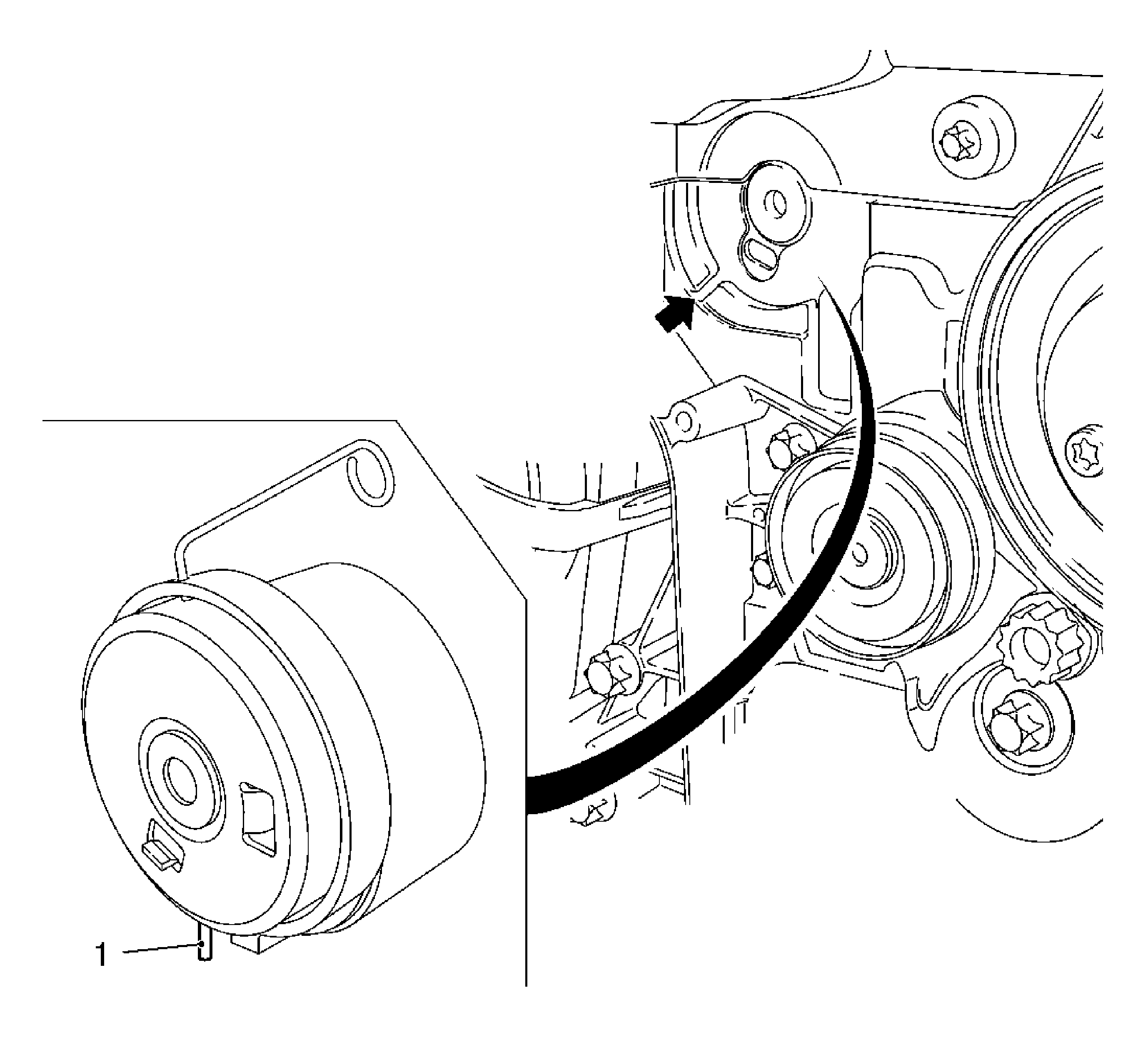
| • | Insert the drive belt tension roller. |
| • | Use a new bolt. |
Tighten
Tighten the bolt to 20 N·m (15 lb ft).
| • | Released leg of spring (1) of the drive belt tension roller must engage in the cut-out (arrow) of the pump module. |
Tighten
Tighten the 3 bolts to 50 N·m (37 lb ft).
Connect the ground connection to the negative terminal.
Tighten
Tighten the nut to 5 N·m (44 lb in).
