Special Tools
| • | KM-6001-A Engine Mount |
| • | KM-6333 Fixing Rod |
| • | MK-6340 Locking Tool |
| • | KM-6625 Flywheel Locking Device |
| • | MK-6628 Locking Tool |
Removal Procedure
- Open the hood.
- Disconnect the battery.
- Remove the air cleaner housing. Refer to Air Cleaner Assembly Replacement.
- Remove the front toothed belt cover (top). Refer to Timing Belt Upper Front Cover Replacement.
- Raise the vehicle by its full height.
- Remove the drive belt tensioner. Refer to Drive Belt Tensioner Replacement.
- Lower the vehicle by its full height.
- Remove the camshaft cover. Refer to Camshaft Cover Replacement.
- Set the engine to TDC (1).
- Prepare the right half of MK-6340 for use on the U 18 XER engine.
- Insert MK-6340 into the camshaft timing gears.
- Insert MK-6628 (1) into camshafts.
- Align camshafts horizontally by the hexagon (arrows) until MK-6628 can be inserted in both camshafts.
- Raise the vehicle by its full height.
- Block the crankshaft.
- Remove the torsional vibration damper.
- Remove the front toothed belt cover (bottom).
- Remove KM-6625 .
- Insert KM-6173 Adapter (3).
- Attach KM-6001-A (1).
- Lower the vehicle by its full height.
- Detach the engine damping block (1) from the side member and the engine damping block support.
- Remove the engine damping block with the bracket.
- Remove the engine damping block support (1).
- Remove the center toothed belt cover (1).
- Stop the toothed belt tensioner.
- Remove the toothed belt tensioner (1).
- Remove the toothed belt.
- Raise the vehicle by its full height.
- Remove KM-6625 .
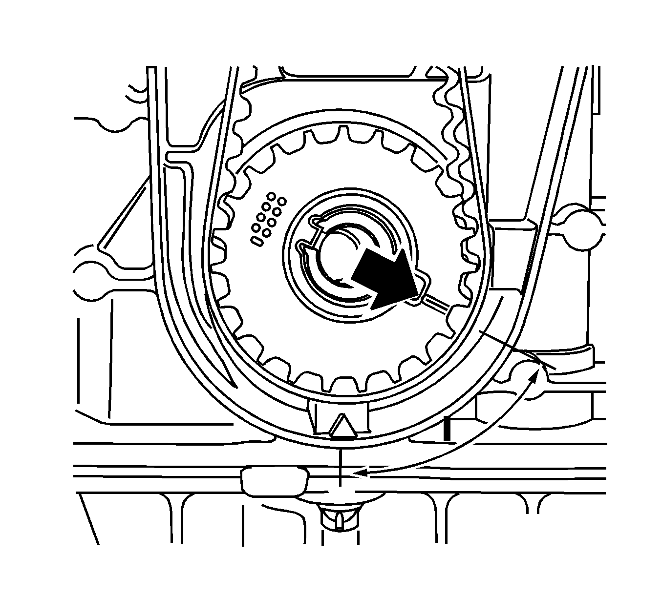
- Turn the crankshaft 60 degrees against the direction of engine rotation.
- Place the collecting basin underneath.
- Remove the closure bolt, exhaust camshaft adjuster.
- Remove the intake camshaft closure bolt.
- Remove MK-6340 .
- Loosen the exhaust camshaft adjuster.
- Remove the exhaust camshaft adjuster.
- Loosen the intake camshaft adjuster.
- Remove the intake camshaft adjuster.
- Remove the rear toothed belt cover.
| 2.1. | Disconnect the negative connection from the ground terminal. |
| 2.2. | Loosen the nut. |
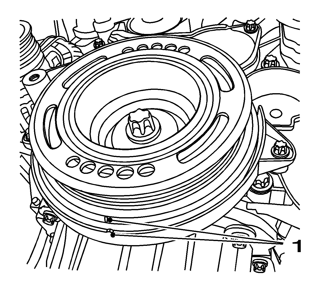
Turn the crankshaft in the direction of engine rotation by the bolt of the torsional vibration damper to cylinder 1 TDC of combustion stroke.
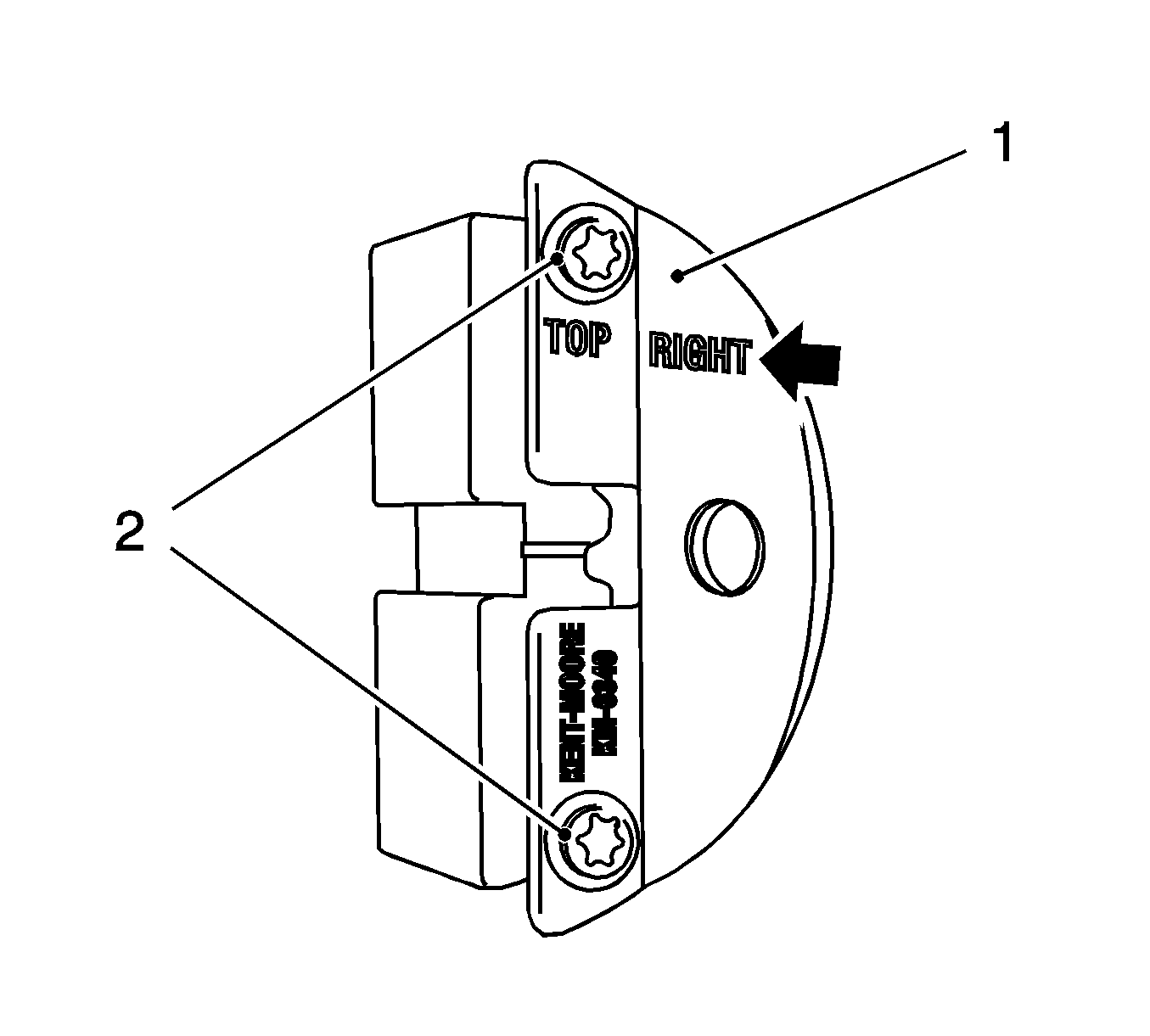
Note: Recognizable from the lettering "Right" (arrow).
| 10.1. | Detach the front panel (1) from MK-6340 . |
| 10.2. | Remove the 2 bolts (2). |
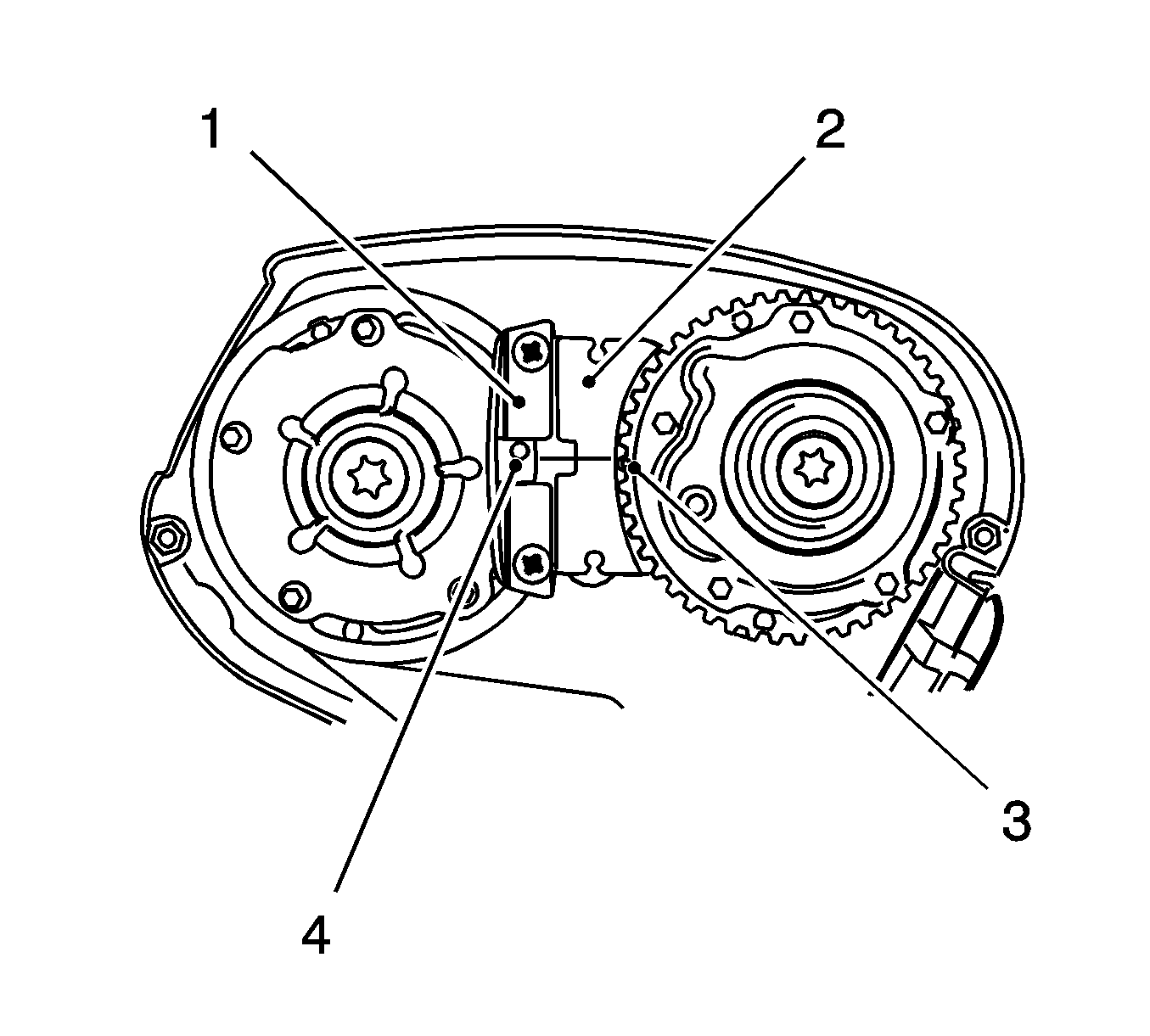
| 11.1. | Insert MK-6340 (1, 2) in the camshaft adjuster as shown. |
| Note: The spot-type marking (4) on the intake camshaft adjuster does not correspond to the groove of MK-6340 during this process but must be somewhat above as shown. |
| 11.2. | The spot type marking (3) on the exhaust camshaft adjuster must correspond to the groove on MK-6340 . |
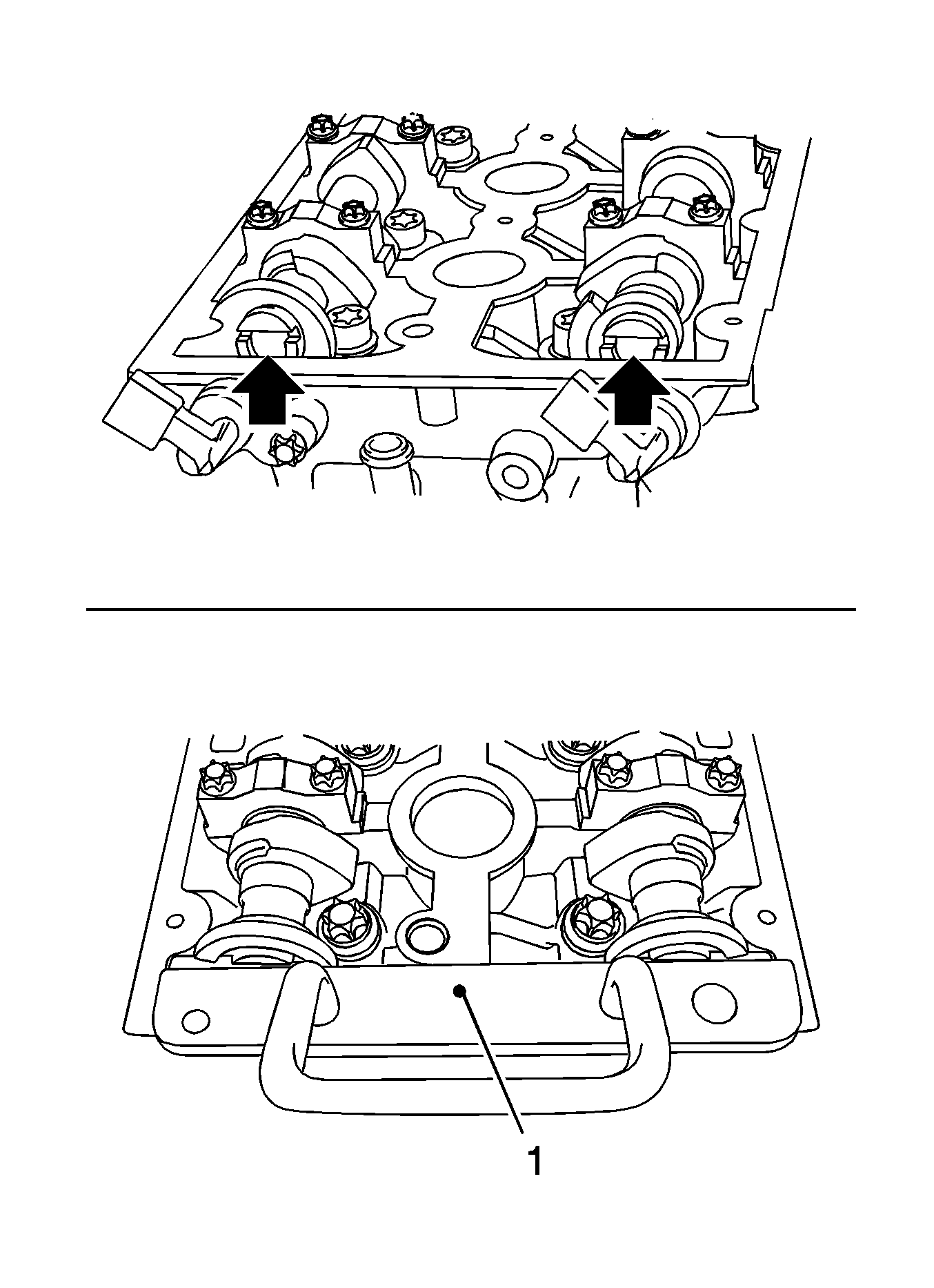
Note: If MK-6628 cannot be inserted, the timing must be set.
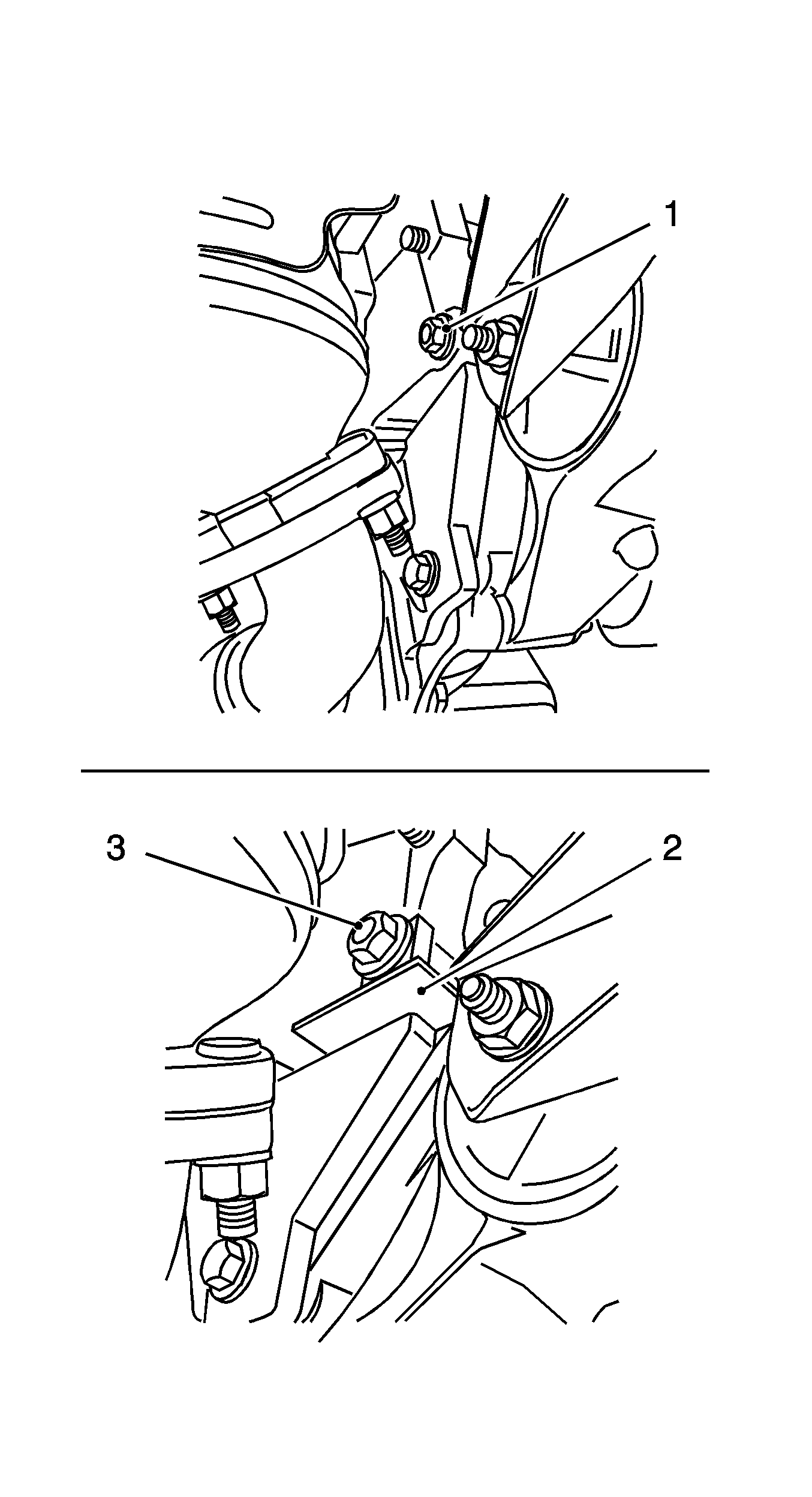
Attach KM-6625 .
| 14.1. | Detach the screwed connection (1). |
| 14.2. | Insert KM-6625 (2). |
| 14.3. | Tighten the screwed connection (3). |
Remove the bolt.
Remove the 4 bolts.
Detach the screwed connection.
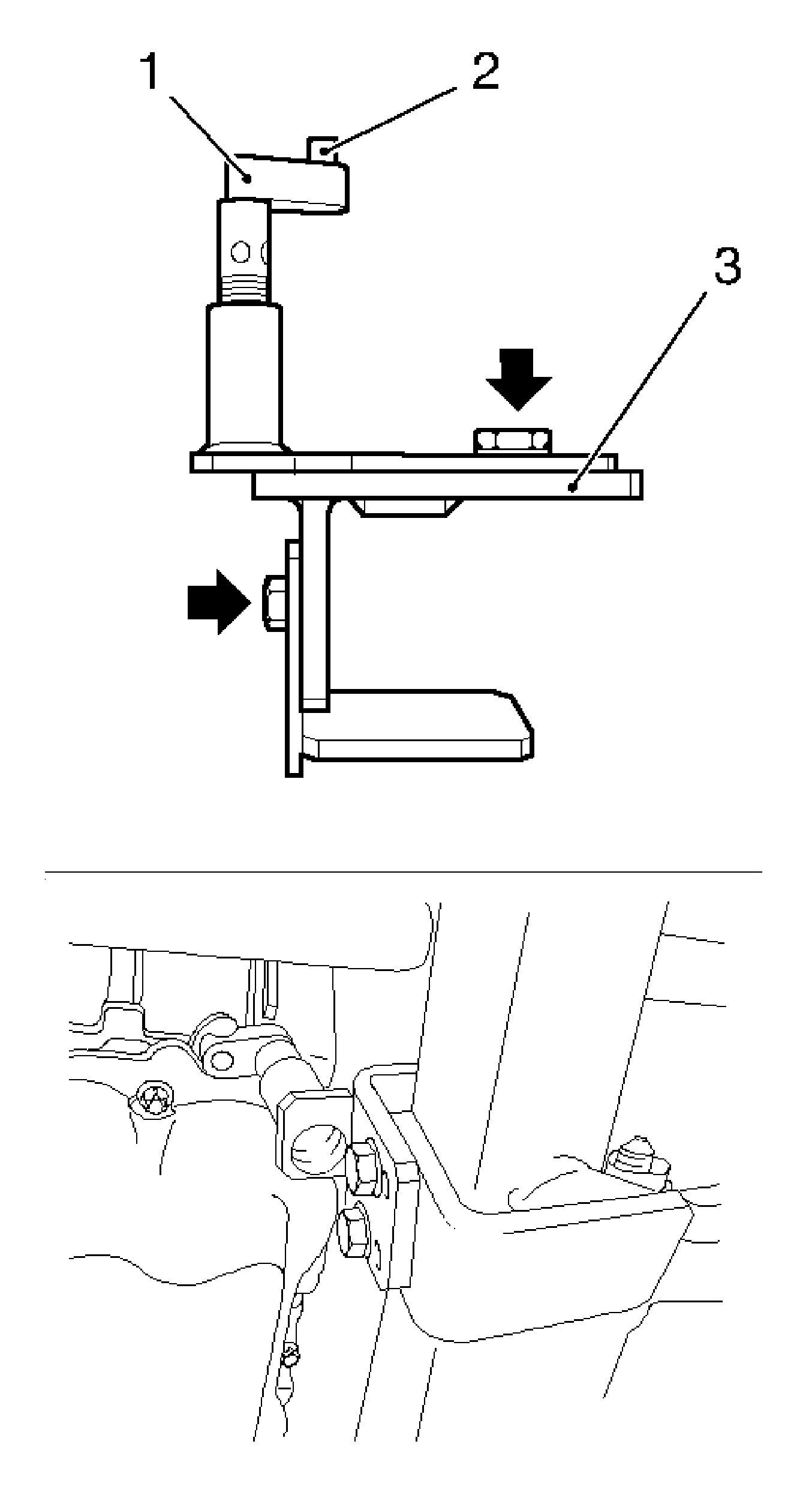
| 18.1. | Loosen the 4 bolts (arrows) and hand-tighten. |
| 18.2. | Align KM-6173 at the frame. |
| 18.3. | Position the support bearing (1). |
| 18.4. | Journal (2) must sit in the mount at the cylinder block. |
| 18.5. | Tighten the 4 bolts. |
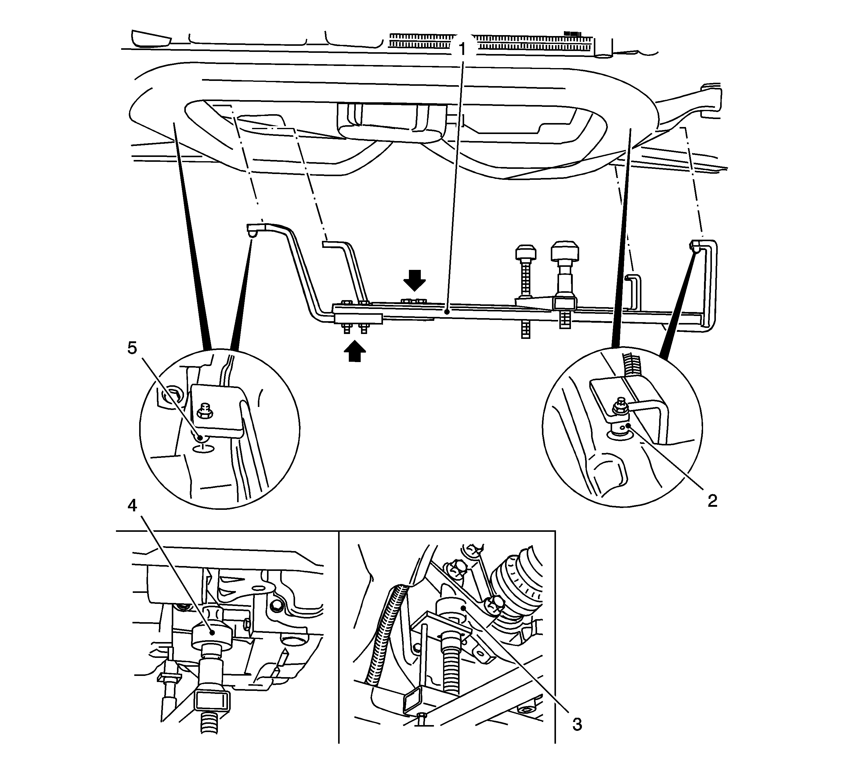
Note: Attaching KM-6001-A guarantees perfect alignment of the drive unit with the frame.
| 19.1. | Loosen the 3 bolts (arrows) in the adjusting rails. |
| 19.2. | Insert KM-6001-A . |
The journals (2, 5) must sit in the guide holes of the frame.
| 19.3. | Tighten the 3 bolts in the adjusting rails. |
| 19.4. | Adjust the support bearings, front (4) and rear (3). |
| Note: The guide journals must be seated free from play in the support bearings. |
| 19.5. | Raise the support bearings up to the stop on the guide journals. |
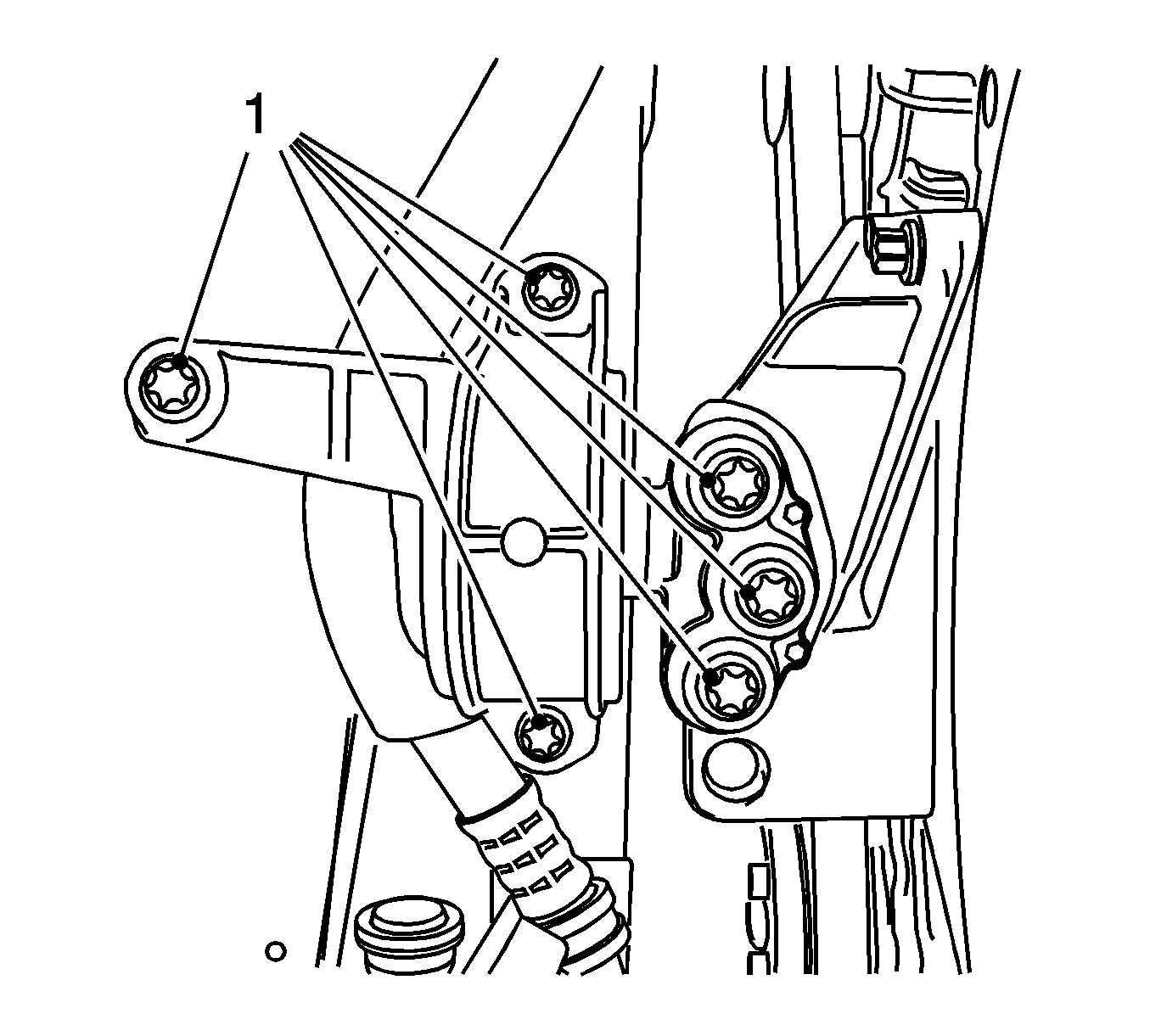
Remove the 6 bolts.
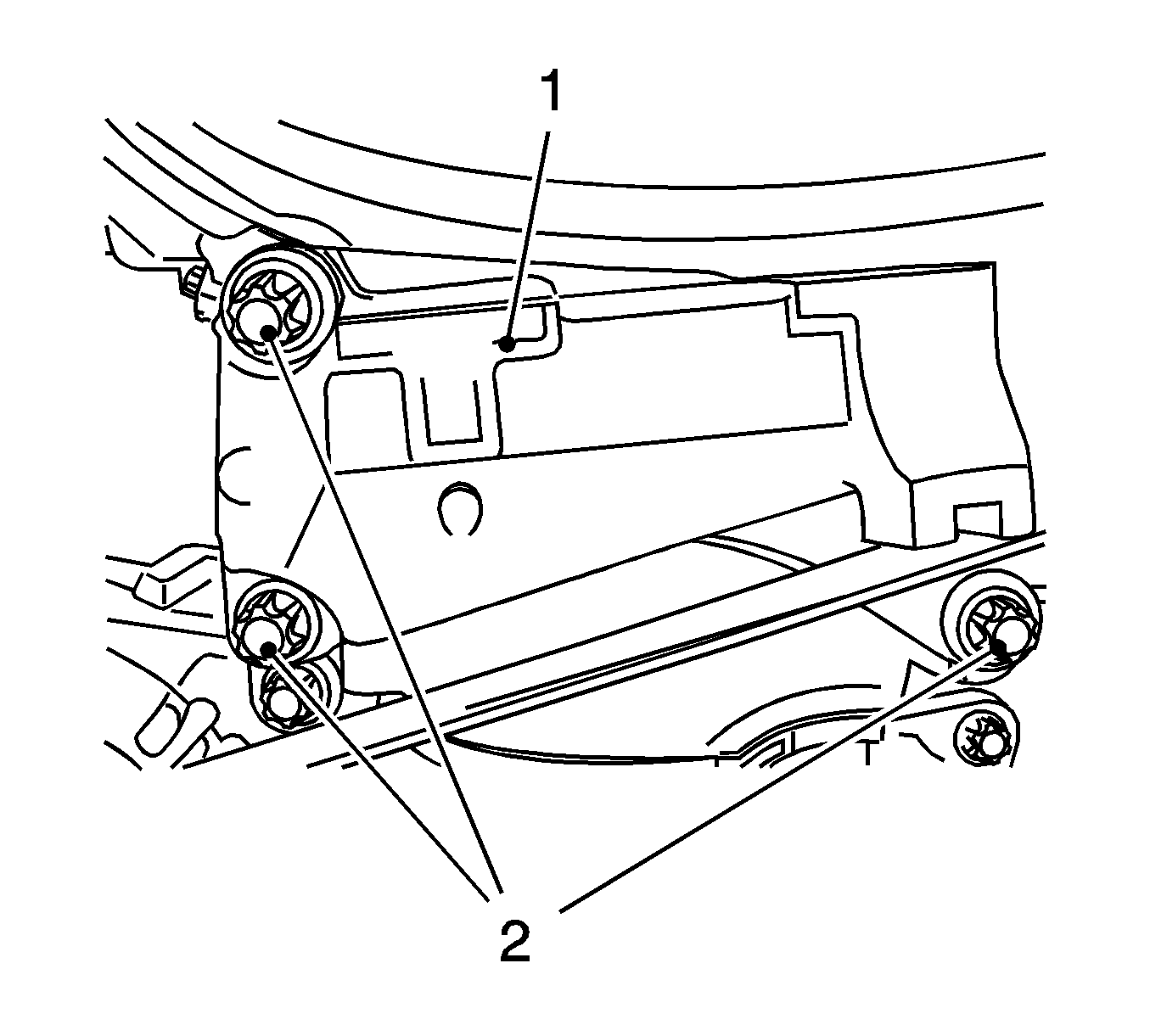
Remove the 3 bolts (2).
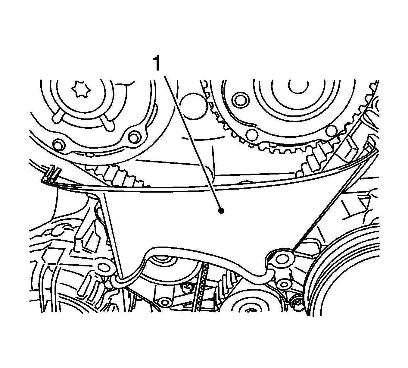
Release 2x from the rear of the toothed belt cover.
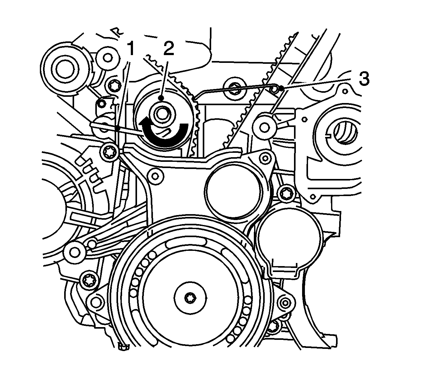
Apply tension to the toothed belt tension roller (2) in the direction of the arrow, using an Allen key (1). Install using KM-6333 (3).
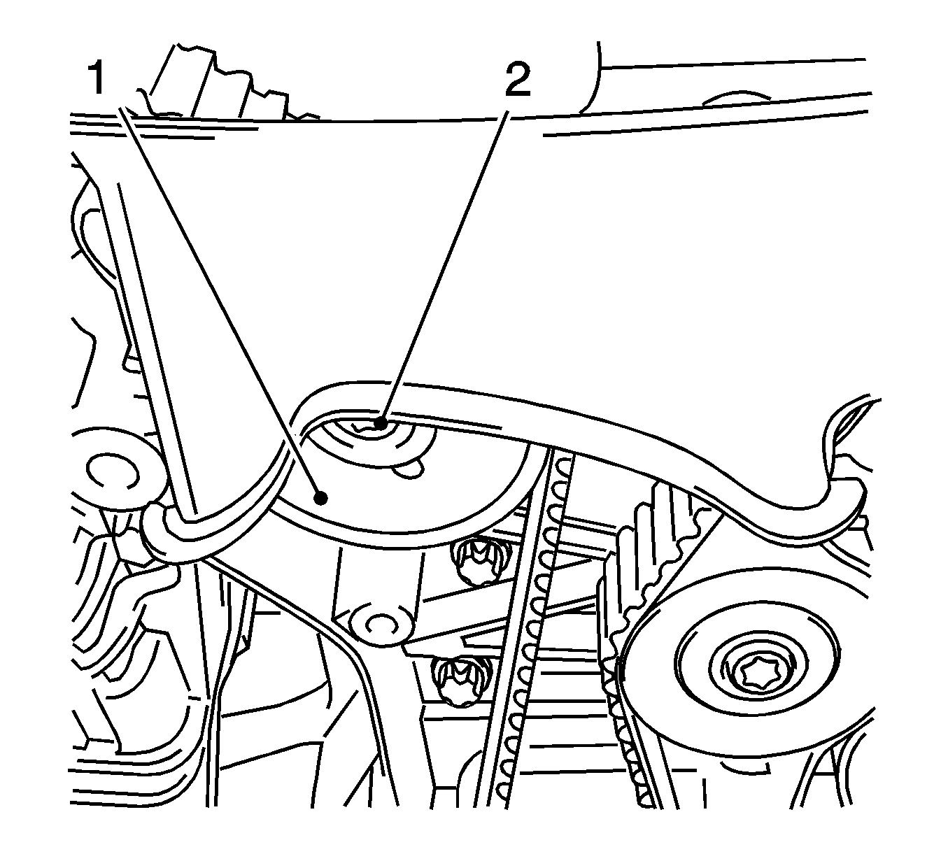
Remove the bolt (2).
Detach the screwed connection.
Counterhold at camshaft hexagon.
Remove the bolt.
Counterhold at camshaft hexagon.
Remove the bolt.
| 39.1. | Release the wiring trough cover. |
| 39.2. | Remove the 4 bolts. |
Installation Procedure
- Clean the 4 threads, rear toothed belt cover.
- Install the rear toothed belt cover.
- Install the intake camshaft adjuster.
- Install the exhaust camshaft adjuster.
- Insert MK-6340 .
- Tighten the exhaust camshaft adjuster.
- Counterhold at camshaft hexagon.
- Tighten the intake camshaft adjuster.
- Counterhold at camshaft hexagon
- Tighten the exhaust camshaft adjuster closure bolt.
- Replace the seal ring.
- Tighten the closure bolt, intake camshaft adjuster.
- Replace the seal ring.
- Remove MK-6628 .
- Raise the vehicle by its full height.
- Position the crankshaft to cylinder number 1 ignition TDC.
- Lower the vehicle by its full height.
- Intake toothed belt tensioner.
- Insert the toothed belt.
- Release tension on the toothed belt tensioner.
- Install the center toothed belt cover.
- Install the support for the engine damping block.
- Install the engine damping block.
- Raise the vehicle by its full height.
- Block the crankshaft.
- Install the front toothed belt cover (lower).
- Install the torsional vibration damper.
- Remove KM-6625 .
- Lower the vehicle by its full height.
- Remove MK-6340 .
- Inspect position of the camshaft sprockets.
- Inspect the camshaft positions.
- Raise the vehicle by its full height.
- Inspect the crankshaft position.
- Install the drive belt tensioner. Refer to Drive Belt Tensioner Replacement.
- Lower the vehicle by its full height.
- Remove MK-6628 .
- Install the camshaft cover. Refer to Camshaft Cover Replacement.
- Remove MK-6340 .
- Install the front toothed belt cover (top). Refer to Drive Belt Replacement.
- Install the air cleaner housing. Refer to Air Cleaner Assembly Replacement.
- Connect the battery.
- For programming procedures, refer to Control Module References.
- Close the hood.
Caution: Refer to Fastener Caution in the Preface section.
| 2.1. | Tighten the 4 new bolts. |
Tighten
Tighten the 4 new bolts to 6 N·m (53 lb in).
| 2.2. | Coat the 4 bolts with locking compound (red). |
| 2.3. | Clip in the wiring trough cover. |
Note: Do not tighten the bolt.
Install the bolt.
Note: Do not tighten the bolt.
Install the bolt.
Note: Note markings on the camshaft sprockets.
Tighten
Tighten the exhaust camshaft adjuster to 65 N·m (48 lb ft) plus 120 degrees plus 15 degrees.
Tighten
Tighten the intake camshaft adjuster to 65 N·m (48 lb ft) plus 120 degrees plus 15 degrees.
Tighten
Tighten the exhaust camshaft adjuster closure bolt to 30 N·m (22 lb ft).
Tighten
Tighten the closure bolt, intake camshaft adjuster to 30 N·m (22 lb ft).
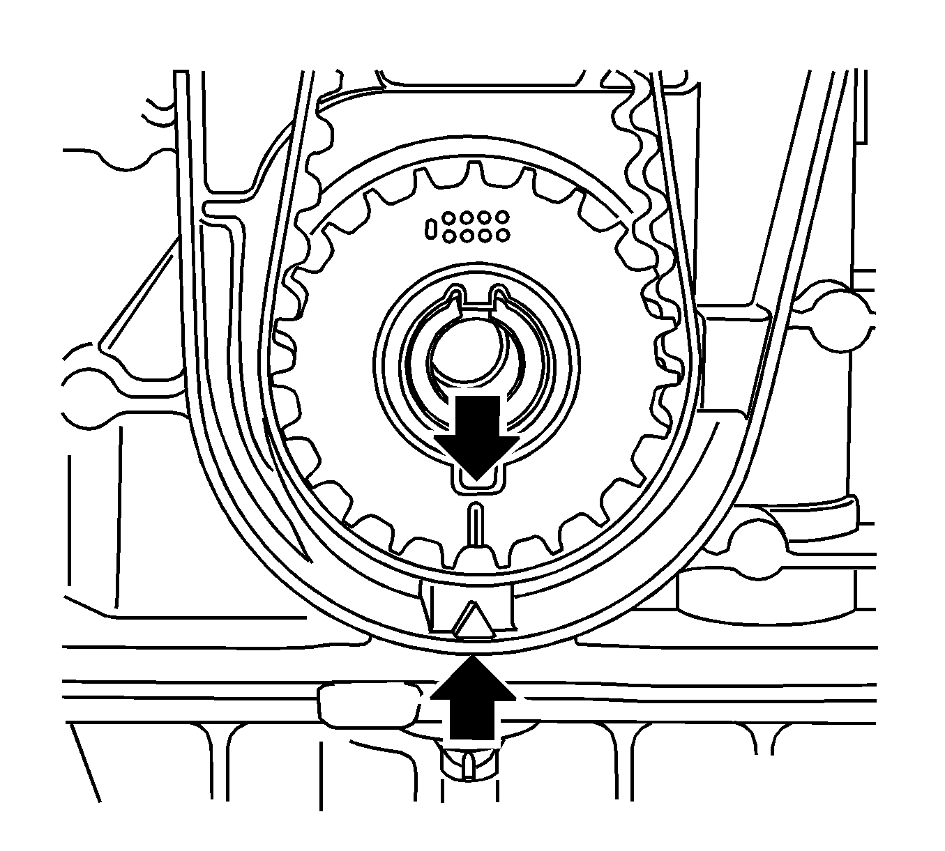
Marking, toothed belt drive gear and oil pump housing adapter must align.
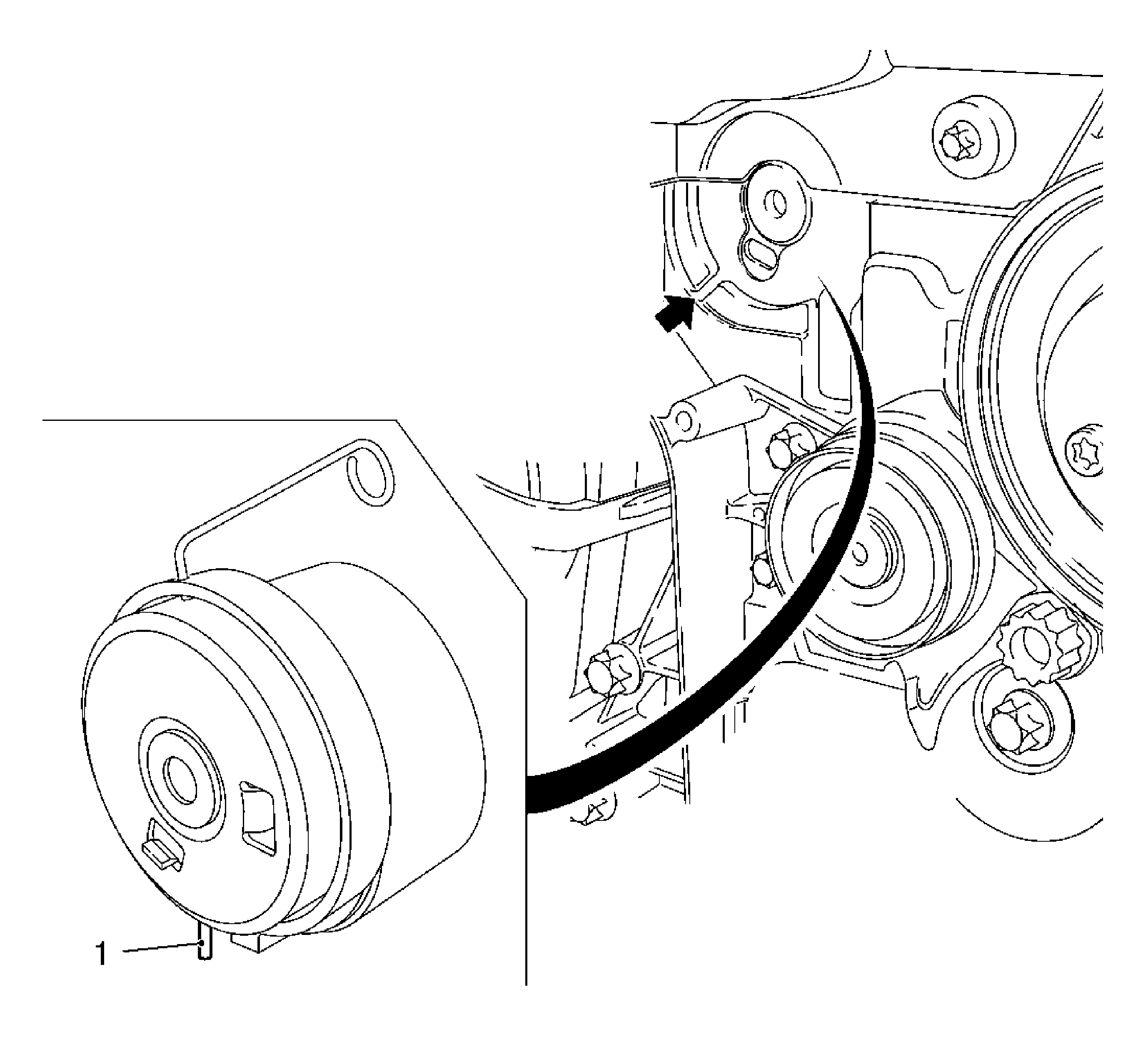
| 14.1. | Insert the toothed belt tension roller. |
| 14.1.1. | Use a new bolt. |
| 14.1.2. | Released leg of spring (1) of the toothed belt tension roller must engage in the cut-out (arrow) of the pump module. |
| 14.2. | Tighten the bolt. |
Tighten
Tighten the bolt to 20 N·m (15 lb ft).
Note: Use assembly tool.
| 16.1. | Apply preliminary tension clockwise to the toothed belt tension roller. |
| 16.2. | Remove KM-6333 . |
Clip on 2x to the toothed belt cover (rear).
Tighten
Tighten the 3 bolt to 50 N·m (37 lb ft).
| 19.1. | Install to the support. |
Tighten
Tighten the 3 bolt to 55 N·m (40 lb ft).
| 19.2. | Install to the side member. |
Tighten
Tighten the 3 bolts to 55 N·m (40 lb ft).
| 21.1. | Insert KM-6625 . |
| 21.2. | Install the bolted connection. |
Tighten
Tighten the 4 bolts to 6 N·m (53 lb in).
Note: New bolt must be coated with screw locking compound (red).
Tighten
Tighten the new bolt to 95 N·m (70 lb ft) plus 30 degrees plus 15 degrees.
| 24.1. | Detach the screwed connection. |
| 24.2. | Tighten the bolted connection. |
Use the new nuts.
| Note: Note marking, camshaft sprockets. |
| 27.1. | Turn the crankshaft 720 degrees in the direction of engine rotation by the bolt on the torsional vibration damper. |
| 27.2. | Insert MK-6340 into the camshaft timing gears. |
Insert MK-6628 in camshafts, align camshafts by hexagon until MK-6628 can be inserted in both camshafts, marking on torsional vibration damper must align with marking on lower part of toothed belt cover.
Attach the bracket.
Tighten
Tighten the 2 bolts.
Connect the negative connection to the ground terminal.
Tighten
Tighten the nut to 5 N·m (44 lb in).
