- Remove all cup tappets. Refer to
Valve Lifter Replacement.
- Remove the spark plugs. Refer to
Spark Plug Replacement.
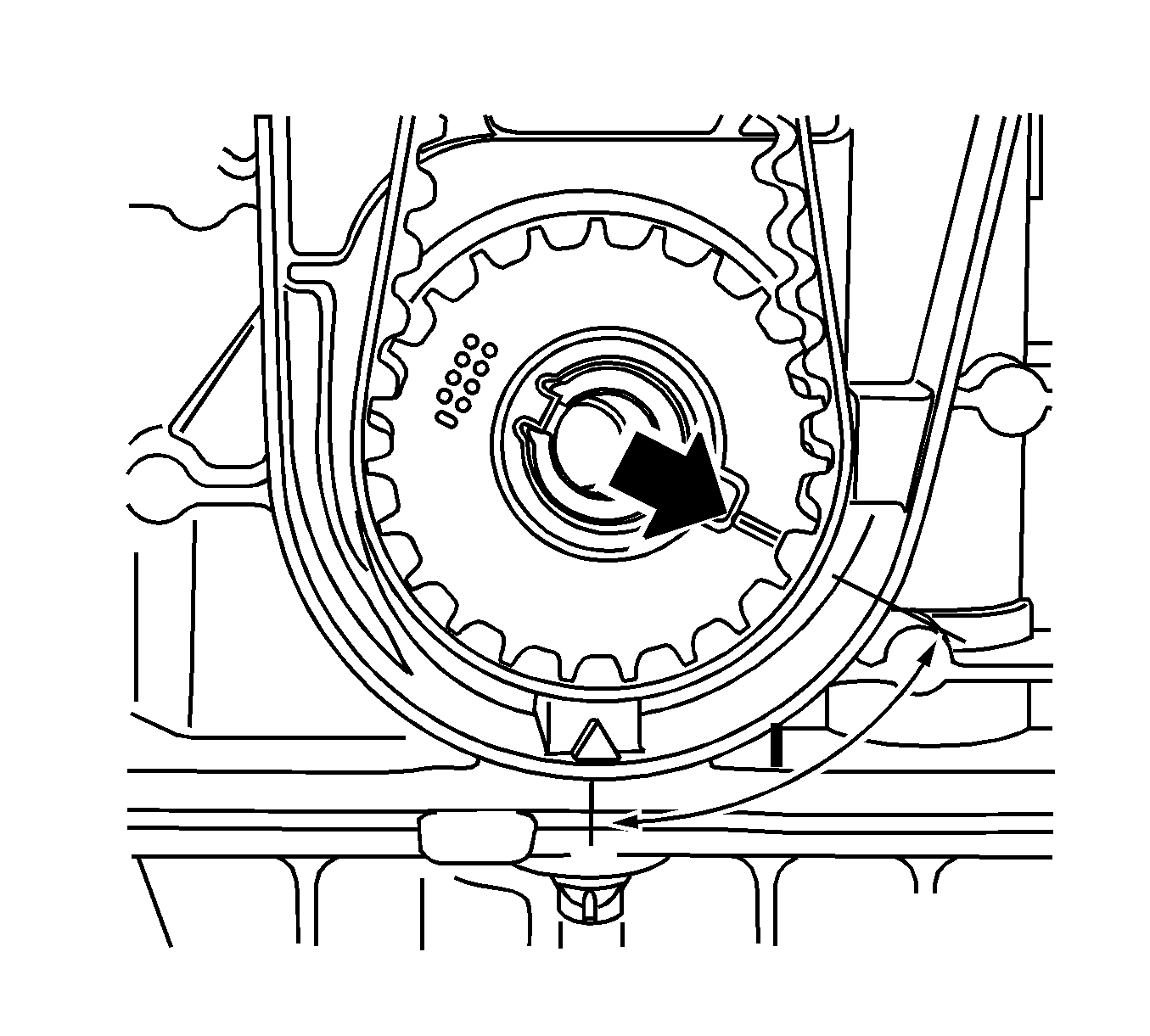
Note: 180 degrees offset to marking ignition TDC cylinder number 1.
- Make alignment mark on the toothed belt drive belt.
- Turn the crankshaft to ignition TDC marking, cylinder number 1.
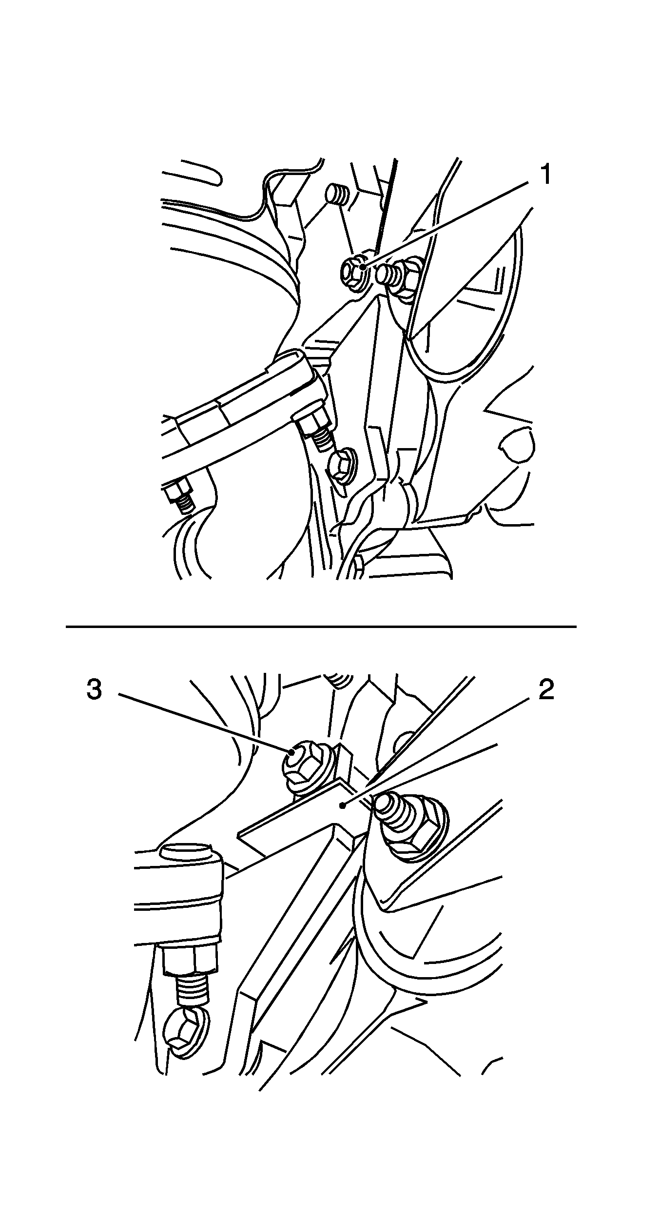
- Block the crankshaft.
Attach
KM-6625 .
| • | Detach the screwed connection (1). |
| • | Tighten the screwed connection (3). |
- Lower the vehicle by its full height.
Caution: Refer to Fastener Caution in the Preface section.
- Install the supports (1).
| • | Adjust the MKM-6086-6 supports. |
| | Adjust the support heads so that they are centered in respect of the support feet (3) and tighten. |
| • | Push the MKM-6086-3 installation shaft (2) into the supports. |
| • | Place both supports with installation shaft onto the cylinders 2 and 3, align in the center over the spark plug bores and bolt on. |
| • | Secure installation shaft. |
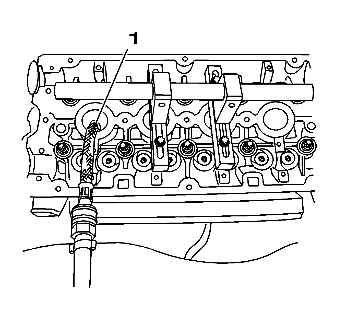
- Attach the MKM-6086-15 pneumatic adapter (1).
| • | Attach the adapter to cylinder number 1. |
| • | Apply compressed air to cylinder number 1. |
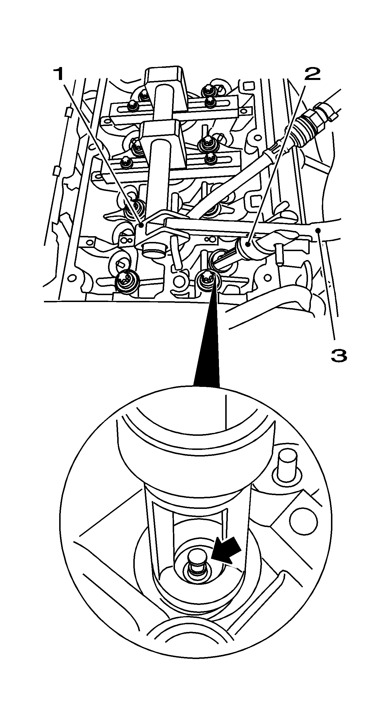
- Attach the MKM-6086-7 lever arm (3).
| • | Complete the lever arm with the MKM-6086-8 joint (1) and the MKM-6086-11 removal head (2). |
| | Note: Removal head must point toward the intake side.
|
| • | Slide assembly on installation shaft over the 1st cylinder |
- Remove the intake valve springs, 1st cylinder.
| | Note: Removal head must be positioned vertically over the valve stem.
|
| • | Carefully push the valve springs down using the lever arm MKM-6086-7. |
| | Note: Observe correct assignment.
|
| • | Remove the valve keepers. |
| • | Remove the valve head and the valve springs. |
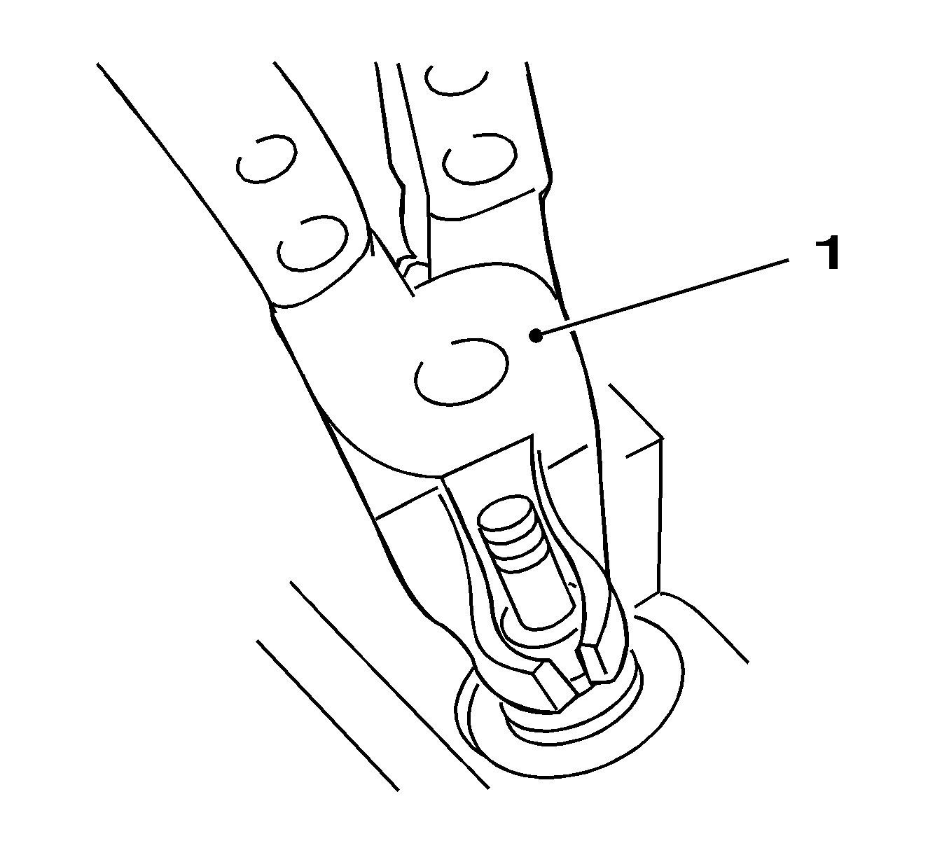
- Remove the valve stem seals.
Pull off with the
SA9102E-A /KM-840 (1) remover.
- Install the valve stem seals.
| • | Coat the valve stem with engine oil. |
| • | Connect the new valve stem seals onto valve stem. |
| • | Using the
KM-958 installer, drive home to limit stop. |
Note: Note manufacturer provisions.
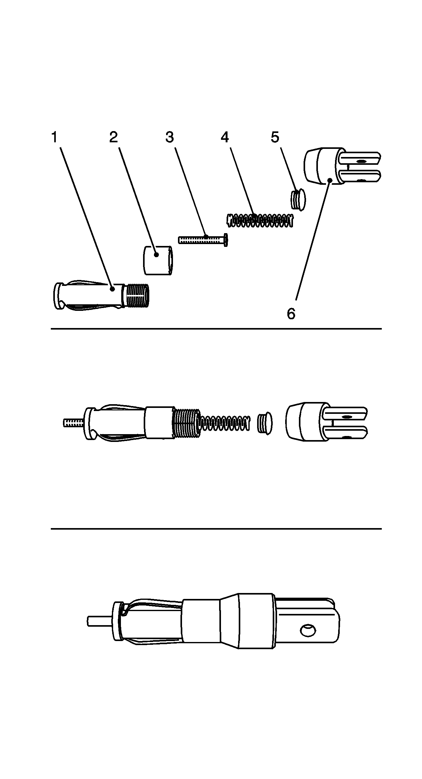
- Complete the MKM-6086-200-1 assembly head.
| • | Use the thrust piece MKM-6086-200-10. |
| • | Put together the assembly head consisting of mount (1), fixing sleeve (2), thrust piece (3), spring (4), screw fixing (5) and lever mount (6). |
- Install the intake valve springs, 1st cylinder.
| • | Insert the valve springs and valve head. |
| | Note: Insert the valve cotters with the tapered end toward the valve.
|
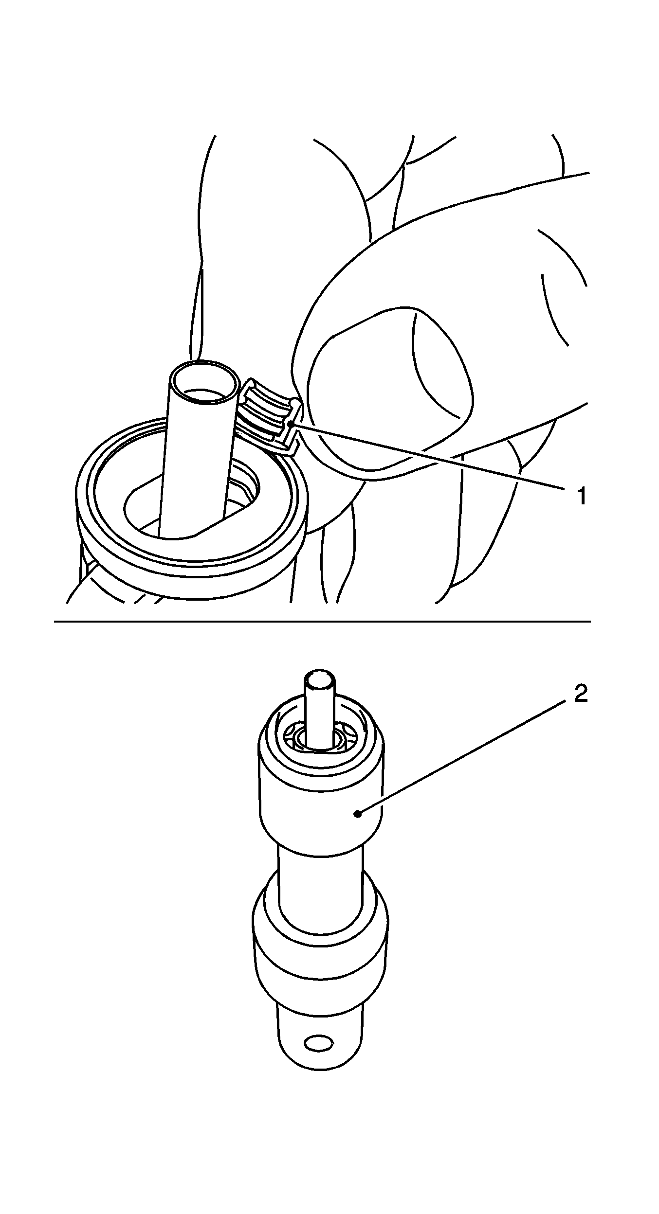
| • | Insert the valve cotters (1) in the assembly head MKM-6086-200-1. |
| - | Slide the plastic clamping sleeve (2) in the direction of the lever arm mount. |
| - | Push the plastic clamping sleeve toward the valve. |
| | Note: Assembly head must stand vertically above the valve stem. Valve cotters must engage audibly.
|
| • | Attach the assembly head to the lever arm. |
| • | Carefully push the valve spring down using the lever arm MKM-6086-7. |
Note: Do not make 2nd attempt without inspecting that both valve cotters are seated in the assembly head.
- Inspect installation position.
Inspect seating of the valve keepers (visual inspection).
- Transfer the lever arm MKM-6086-7.
| • | Detach the assembly head. |
| | Note: Removal head must point toward the exhaust side.
|
| • | Attach the removal head. |
- Remove the exhaust valve springs, 1st cylinder.
| • | Carefully push the valve springs down using the lever arm MKM-889-12. |
| | Note: Removal head must be positioned vertically over the valve stem.
|
| • | Remove the valve keepers |
| | Note: Observe correct assignment.
|
| • | Remove the valve head and valve springs. |
- Replace the valve stem seals.
| • | Pull off with the
SA9102E-A /KM-840 remover. |
| • | Coat the valve stem with engine oil. |
| • | Connect the new valve stem seals onto the valve stem. |
| • | Using the
KM-958 installer, drive home to limit stop. |
- Attach the MKM-6086-7 lever arm.
| • | Insert the valve springs and valve head. |
| • | Insert the valve wedges in the MKM-889-2 assembly head. |
| | Note: Insert the valve cotters with the tapered end toward the valve.
|
| - | Push the plastic clamping sleeve toward the lever arm mounting |
| - | Push the plastic clamping sleeve toward the valve. |
| | Note: Assembly head must stand vertically above the valve stem. Valve cotters must engage audibly.
|
| • | Attach the assembly head to the lever arm. |
| | Note: Do not make 2nd attempt without inspecting that both valve cotters are seated in the assembly head.
|
| • | Carefully push the valve spring down using the lever arm MKM-889-12. |
- Inspect installation position.
Inspect seating of the valve keepers (visual inspection).
- Transfer the pneumatic adapter MKM-6086-15.
| • | Interrupt the compressed air feed. |
| • | Remove the adapter from cylinder number 1. |
| • | Install the adapter to cylinder number 4. |
| • | Apply compressed air to cylinder number 4. |
- Replace the valve stem seal of cylinder 4 by analogy with step 7-20.
- Remove the pneumatic adapter MKM-6086-15.
| • | Interrupt the compressed air feed. |
| • | Remove the adapter from cylinder number 4. |
- Raise the vehicle by its full height.
- Remove
KM-6625 .
Detach the screwed connection.
- Set the crankshaft to ignition TDC of cylinder 3.
Note: Alignment marking on toothed belt drive wheel must align with marking on rear toothed belt cover.
- Turn crankshaft evenly by 180 degrees.
- Block the crankshaft.
Install
KM-6625 . Tighten the bolted connection.
- Lower the vehicle by its full height.
- Replace the valve stem seal of cylinders 2 and 3 by analogy with Step 7 to Step 21.
- Remove the pneumatic adapter MKM-6086-15.
| • | Interrupt the compressed air feed. |
| • | Remove the adapter from cylinder number 3. |
- Remove the automatic valve spring lever
MKM-6086 .
| • | Release the installation shaft. |
| • | Remove both supports with the installation shaft. |
| • | Remove the installation head from the lever arm. |


