Special Tools
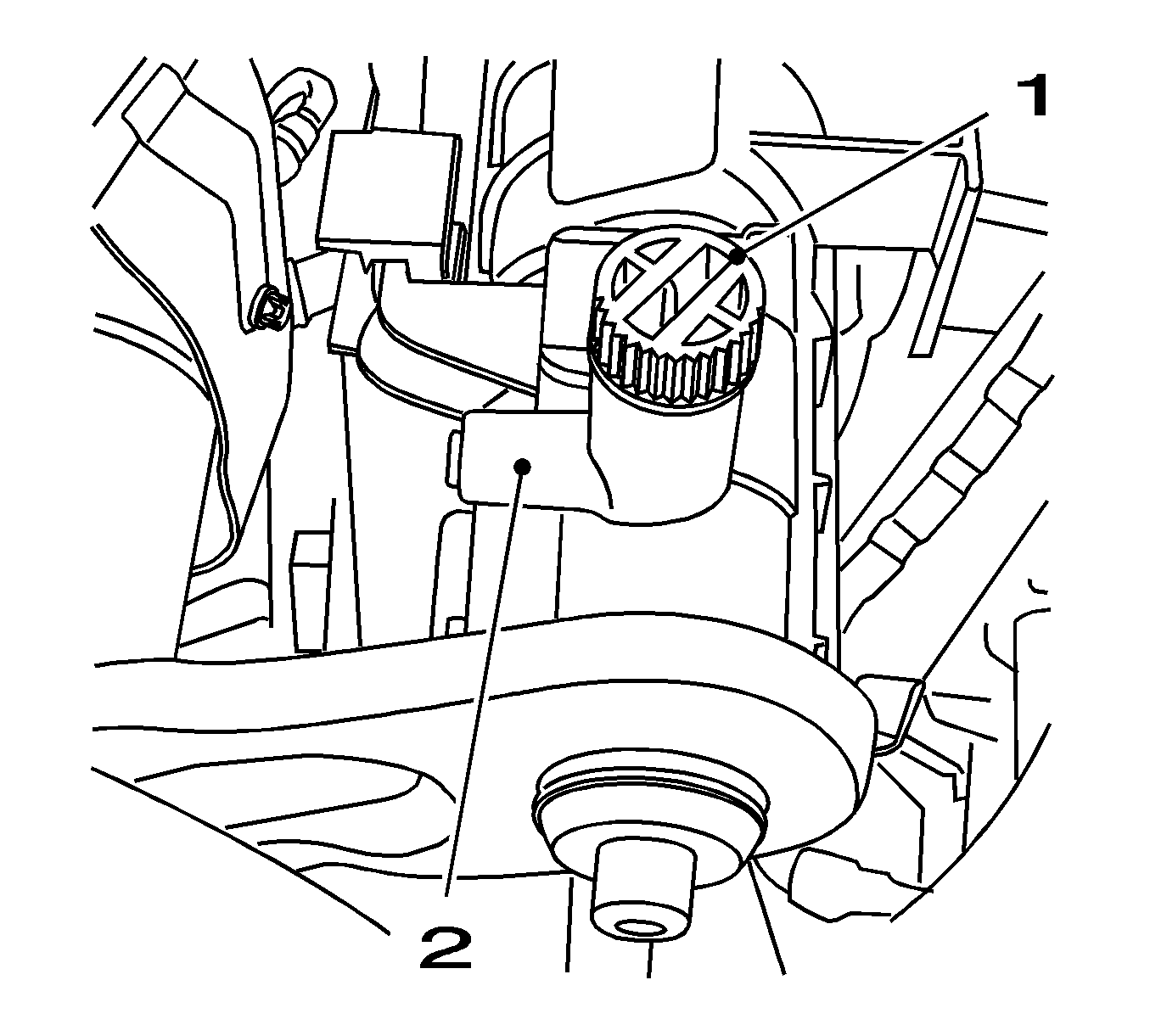
- Drain the coolant.
| 1.1. | Place a drip pan underneath. |
| 1.2. | Connect a suitable hose to the drain connection (2). |
| 1.3. | Open the coolant drain screw (1). |
| 1.5. | Close the coolant drain screw. |
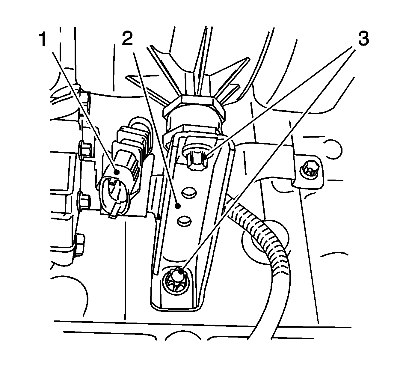
- Remove the intake manifold support (2).
| 2.1. | Disconnect the catalytic converter control oxygen sensor wiring harness plug. |
| 2.2. | Remove the wiring harness plug (1) from the bracket. |
| 2.3. | Remove the 2 bolts (3). |
- Remove the wiring harness from the intake manifold.
- Remove the air cleaner housing. Refer to
Air Cleaner Assembly Replacement.
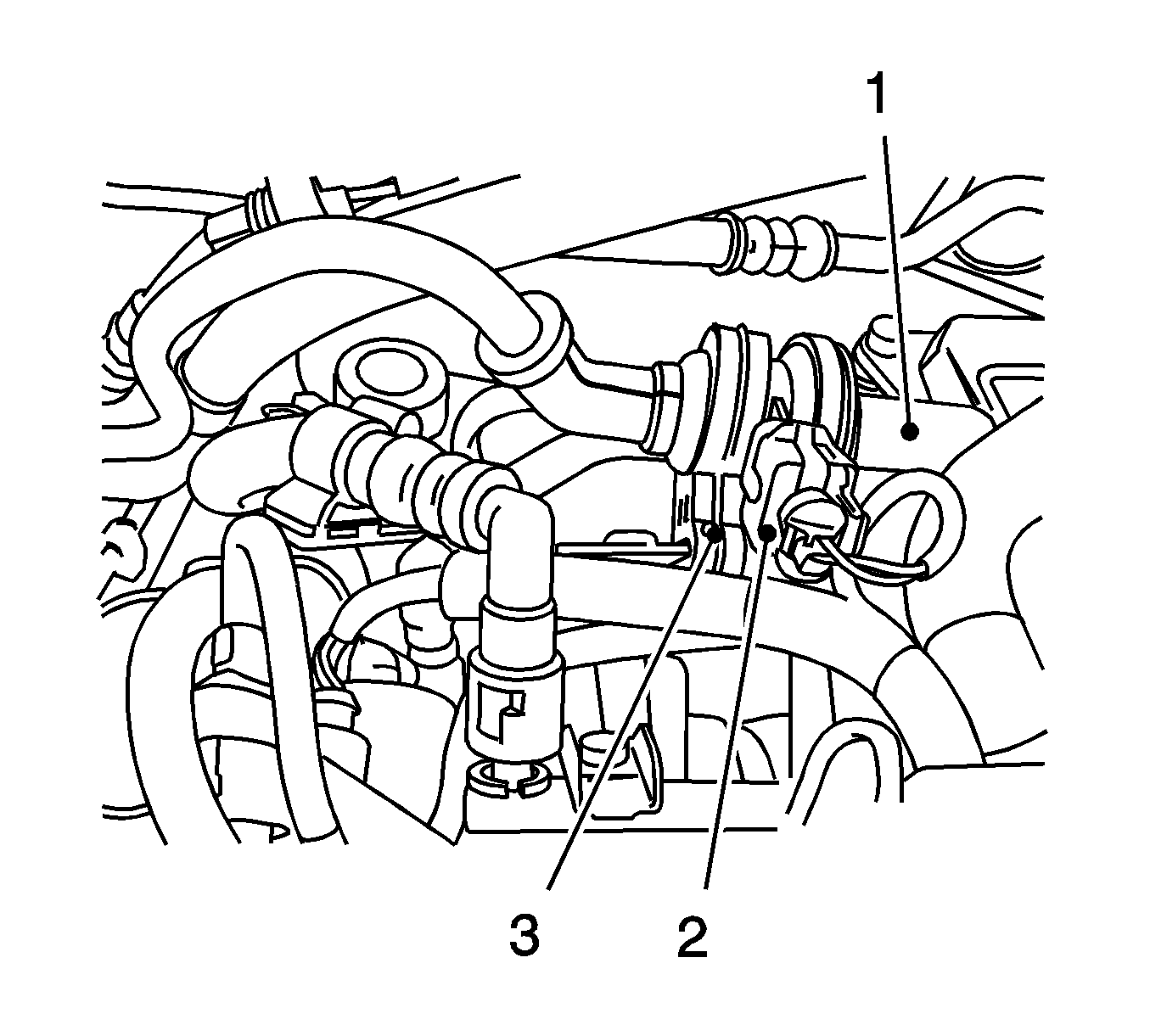
- Disconnect the tank vent valve from the intake manifold.
| 5.1. | Disconnect the wiring harness plug (2). |
| 5.2. | Disconnect the rubber mounting (3) from the bracket. |
| 5.3. | Disconnect the line (1) from the intake manifold. |
| 5.4. | Set the tank vent valve aside. |
- Place a drip pan underneath.
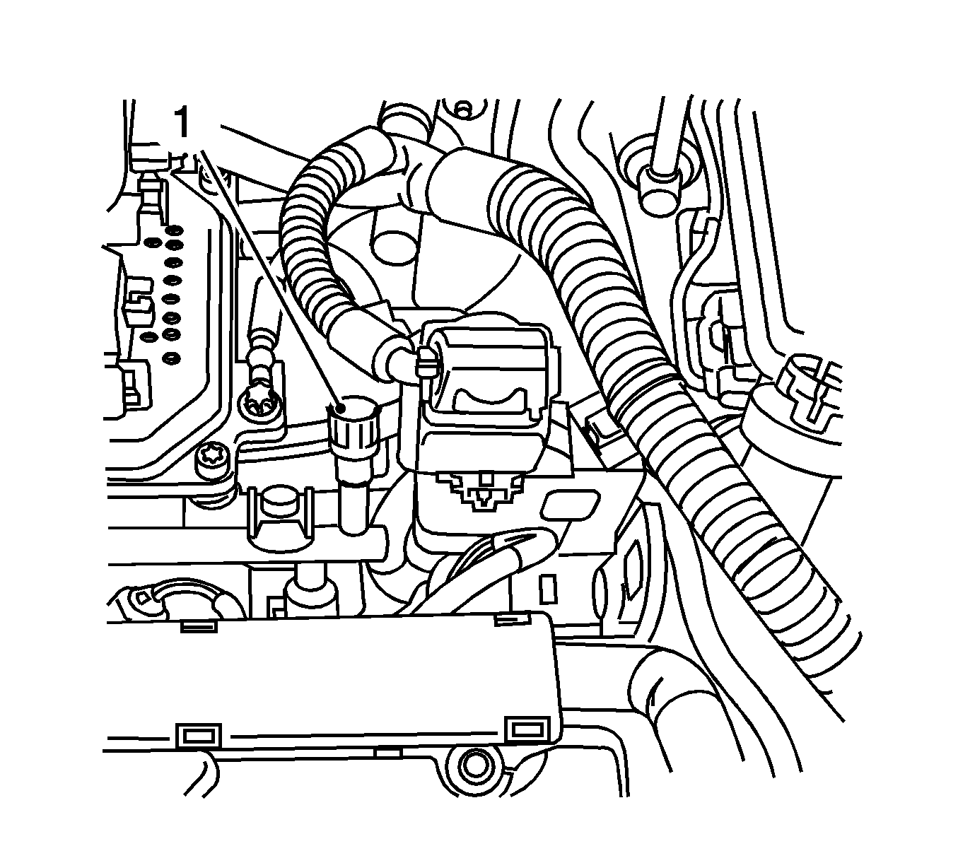
- Using the
KM-J-34730-91
, release the fuel pressure via the test connection (1).
Collect the fuel in a suitable container -
observe safety regulations and national legislation.
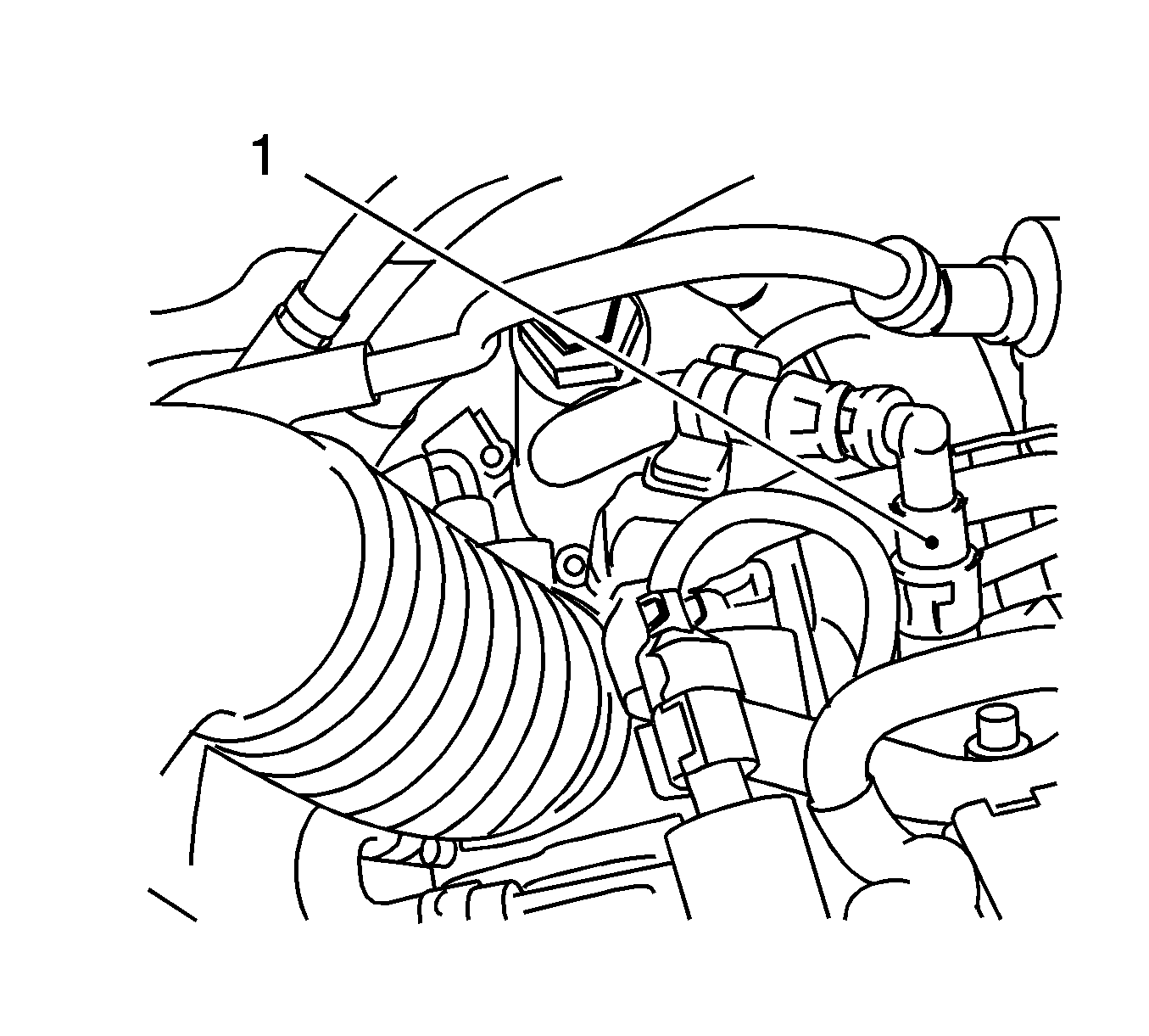
- Remove the fuel return line (1).
| 8.1. | Using the
J 37088-A
, remove the quick-release fitting. |
| 8.2. | Seal the fuel line and fuel rail with
KM-807
. |
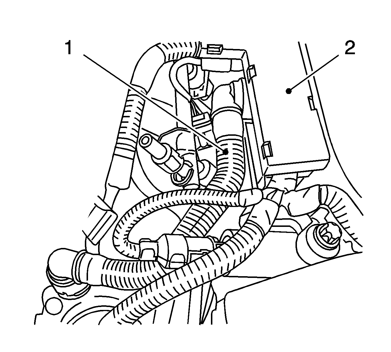
- Remove the engine venting pipe (1).
| 9.1. | Remove the wiring trough (2) from the cylinder head cover. |
| 9.2. | Disconnect the 2 quick-release fittings. |
- Remove the engine control module. Refer to
Engine Control Module Replacement.
- Remove the engine management wiring harness.
| 11.1. | Disconnect the 7 wiring harness plugs: |
| • | The air mass flow meter |
| • | The throttle valve module |
| • | The valve, intake camshaft adjustment |
| 11.2. | Remove the 2 wiring harness brackets. |
| 11.3. | Place the wiring harness to the side. |
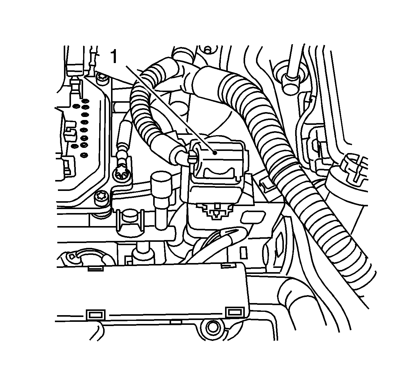
- Disconnect the wiring harness plug (1).
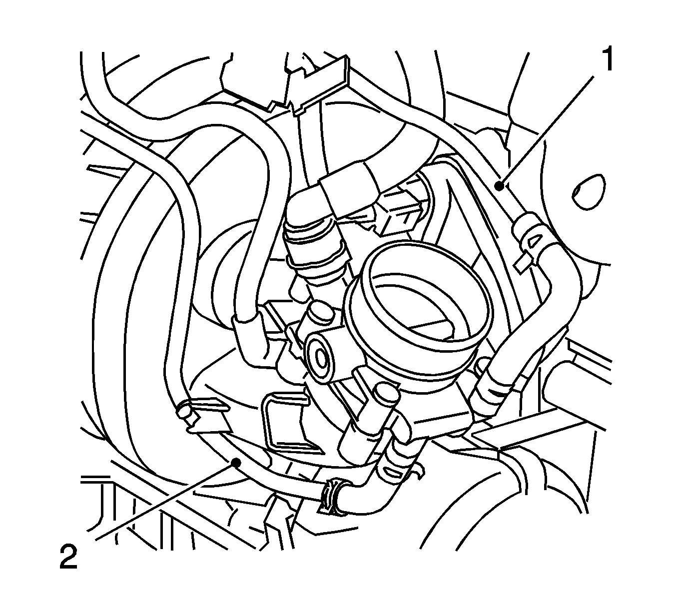
- Remove the supply line, fuel/air mixture preheating (1).
| 13.1. | Disconnect from the thermostat housing. |
| 13.2. | Disconnect the quick-release fitting. |
| 13.3. | Disconnect from the throttle valve module. |
| 13.5. | Disconnect from the intake manifold. |
| 13.6. | Remove 4 from bracket. |
- Remove the return line, fuel/air mixture preheating (2).
| 14.1. | Remove from the throttle valve module. |
| 14.3. | Remove from the coolant expansion tank. |
| 14.5. | Remove from the intake manifold. |
| 14.6. | Remove the 3 brackets. |

- Unclip the wiring trough (2) from the cylinder head cover.
- Disconnect the 2 quick-release fittings.
- Remove the engine venting pipe (1).

- Remove the engine management wiring harness.
| 18.1. | Disconnect the following 9 wiring harness plugs: |
| - | Valve, intake camshaft adjustment |
| 18.2. | Unclip 2 wiring harness brackets. |
| 18.3. | Put the wiring harness to the side. |
- Place a collecting basin underneath.
- Using the
KM-J-34730-91
, release fuel pressure via the test connection (1).
Collect exiting fuel in a suitable container. Observe safety regulations and national legislation.

- Using the
KM-796-A
, undo the quick-release fitting.
- Using the
KM-807
, seal the fuel line and fuel rail.
- Remove the fuel return line (1).
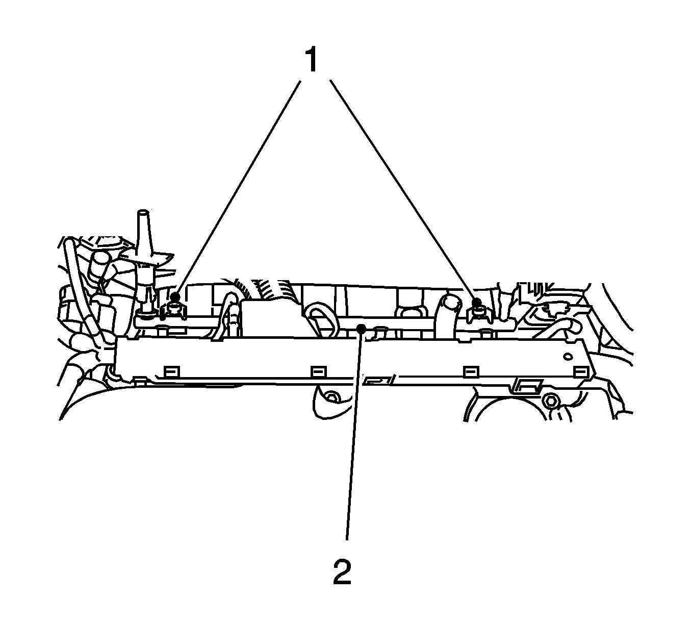
- Remove the 2 fuel rail bolts (1) and the fuel rail (2).
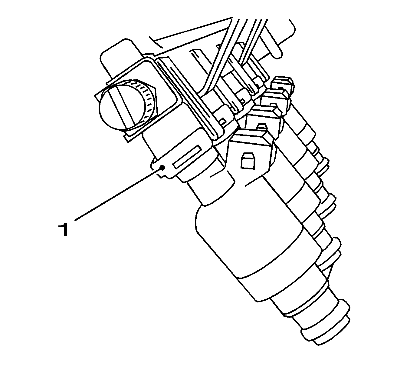
- Remove the 4 retaining clamps (1) and the injectors.
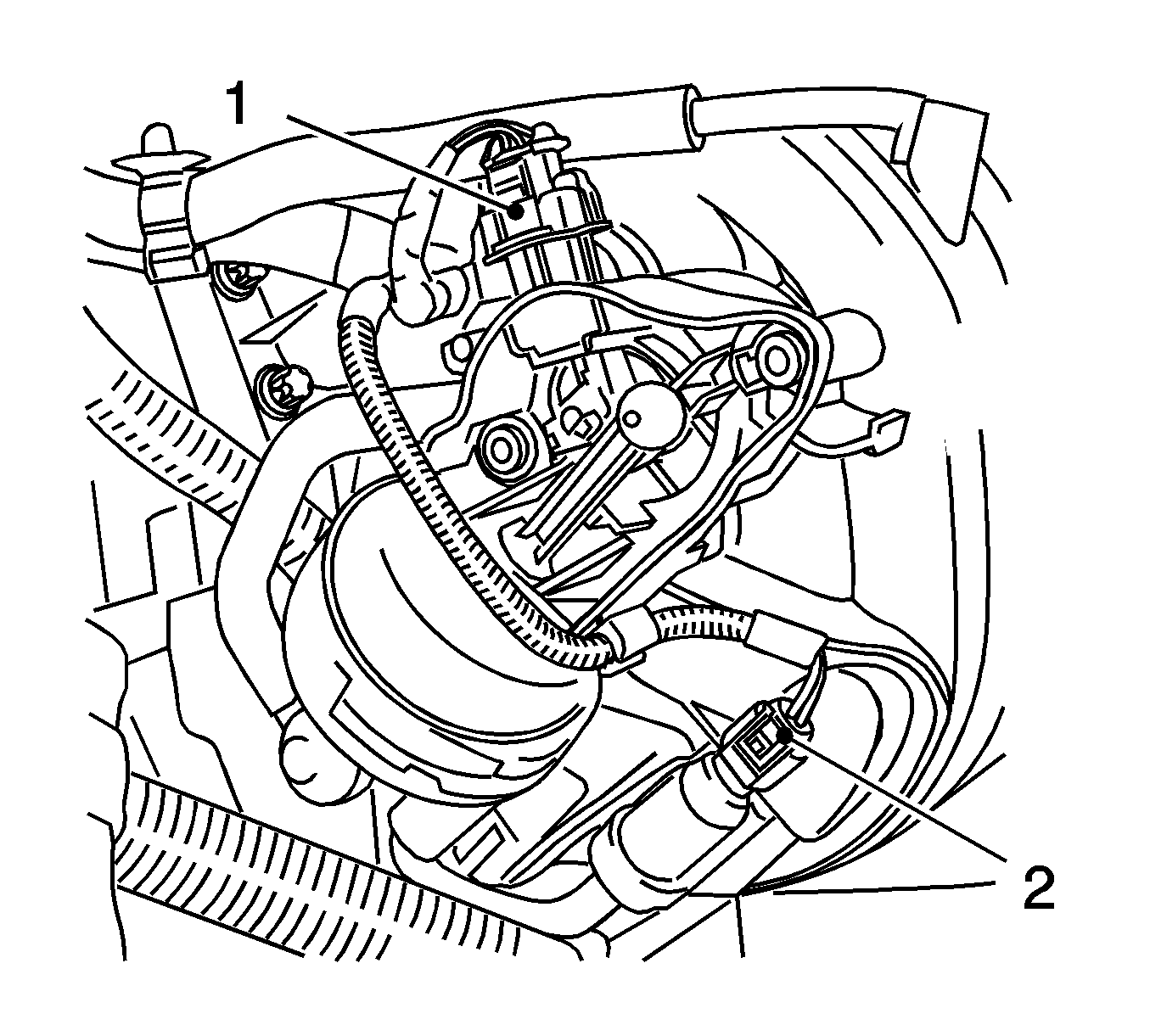
- Disconnect the 2 wiring harness plugs.
| • | Wiring harness plug, vacuum unit change-over valves (1) |
| • | Wiring harness plug, change-over valves for solenoid valve (2) |
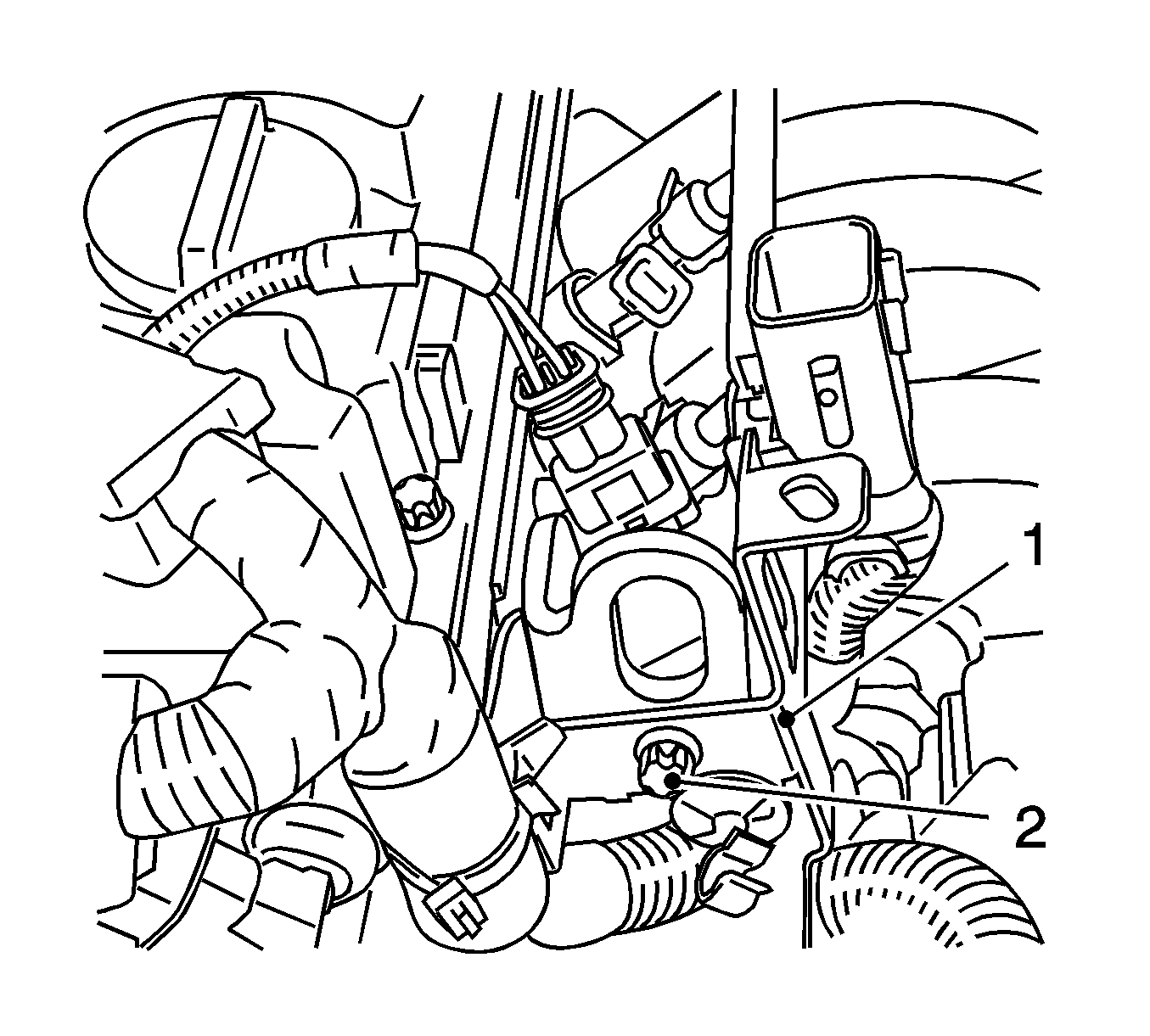
- Disconnect the wiring harness bracket (1) from the engine transport shackle.
- Remove the bolt (2).
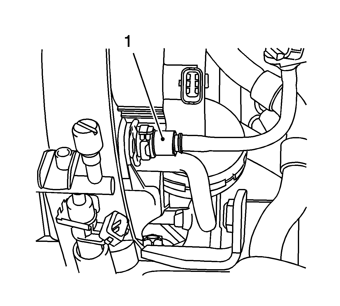
- Disconnect the brake servo vacuum line (1) from the intake manifold.
Disconnect the quick-release fitting.
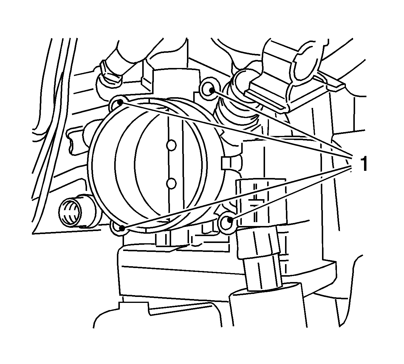
- Remove the 4 throttle valve module bolts (1).
- Remove the throttle valve module.
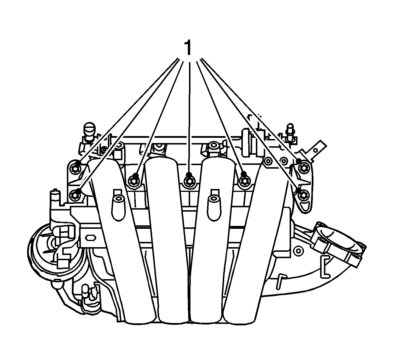
- Remove the 7 intake manifold bolts (1).
- Remove the intake manifold.
- Remove the 2 wiring harness bracket bolts.
- Remove the wiring harness bracket.
- Remove the fuel rail system.


