- Open the hood.
- Disconnect the battery.
| • | Detach the ground connection from the ground terminal. |
- Remove the air cleaner housing. Refer to
Air Cleaner Assembly Replacement.
- Remove the front toothed belt cover (top). Refer to
Timing Belt Upper Front Cover Replacement.
- Remove the camshaft cover. Refer to
Camshaft Cover Replacement.
- Raise the vehicle by its full height.
- Remove the drive belt tensioner. Refer to
Drive Belt Tensioner Replacement.
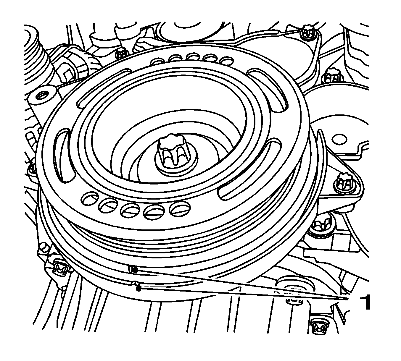
- Set the engine to TDC.
Turn the crankshaft in the direction of engine rotation by the bolt of the torsional vibration damper to cylinder 1 TDC of combustion stroke.
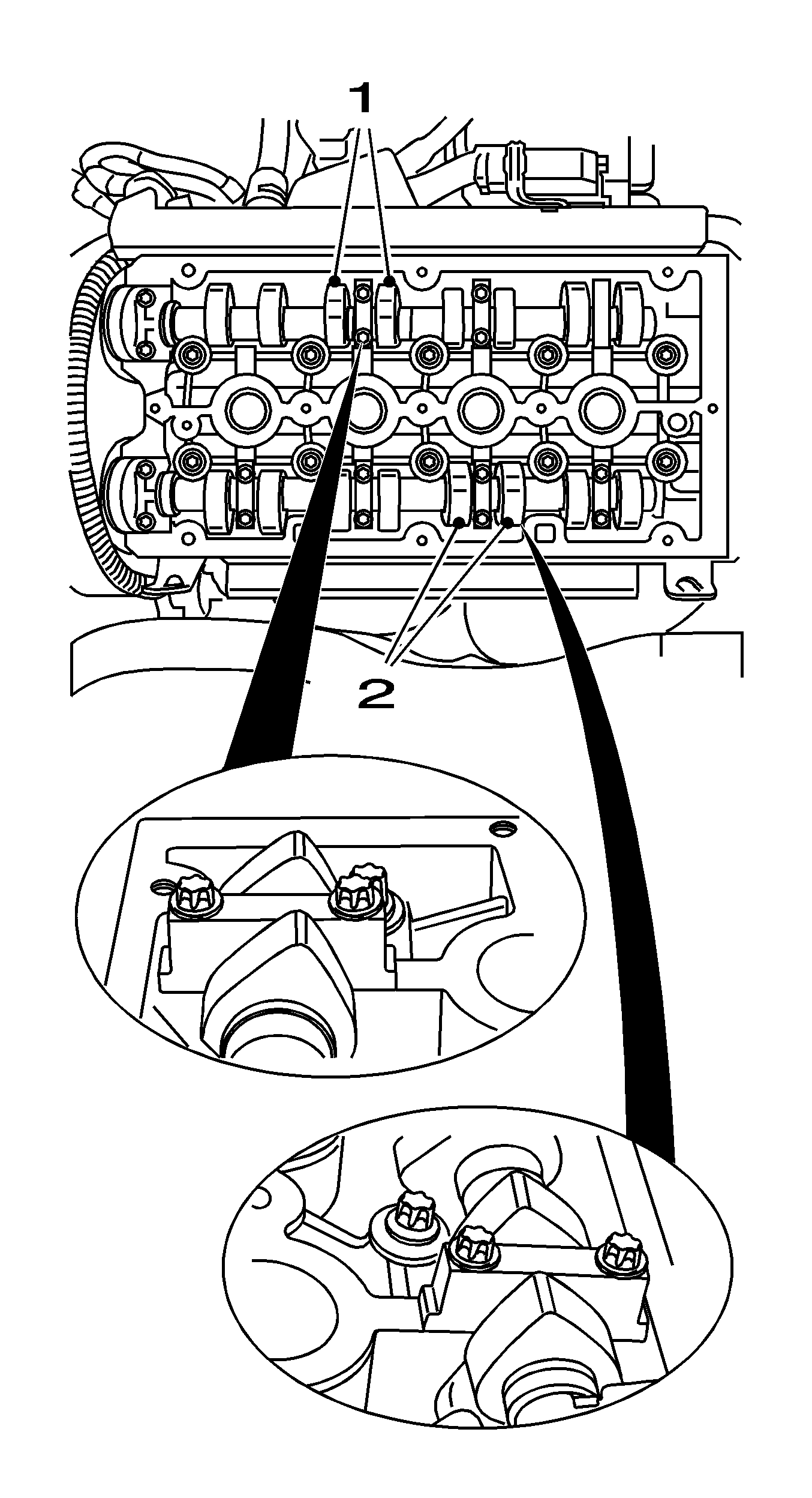
- Cams at the intake side of cylinder number 2 (1) and the exhaust side of cylinder number 3 (2) are on top and tilted slightly towards the inside to the same extent.
- Inspect valve lash.
Prescribed Valve Lash
| • | Intake valves - 0.21-0.29 (nominal value 0.25 mm) |
| • | Exhaust valves - 0.27-0.35 mm (nominal value 0.30 mm) |
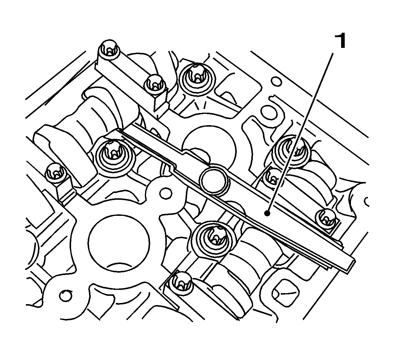
- Inspect the 4 valves.
| • | Inspect valve lash with
KM-6361 (1). |
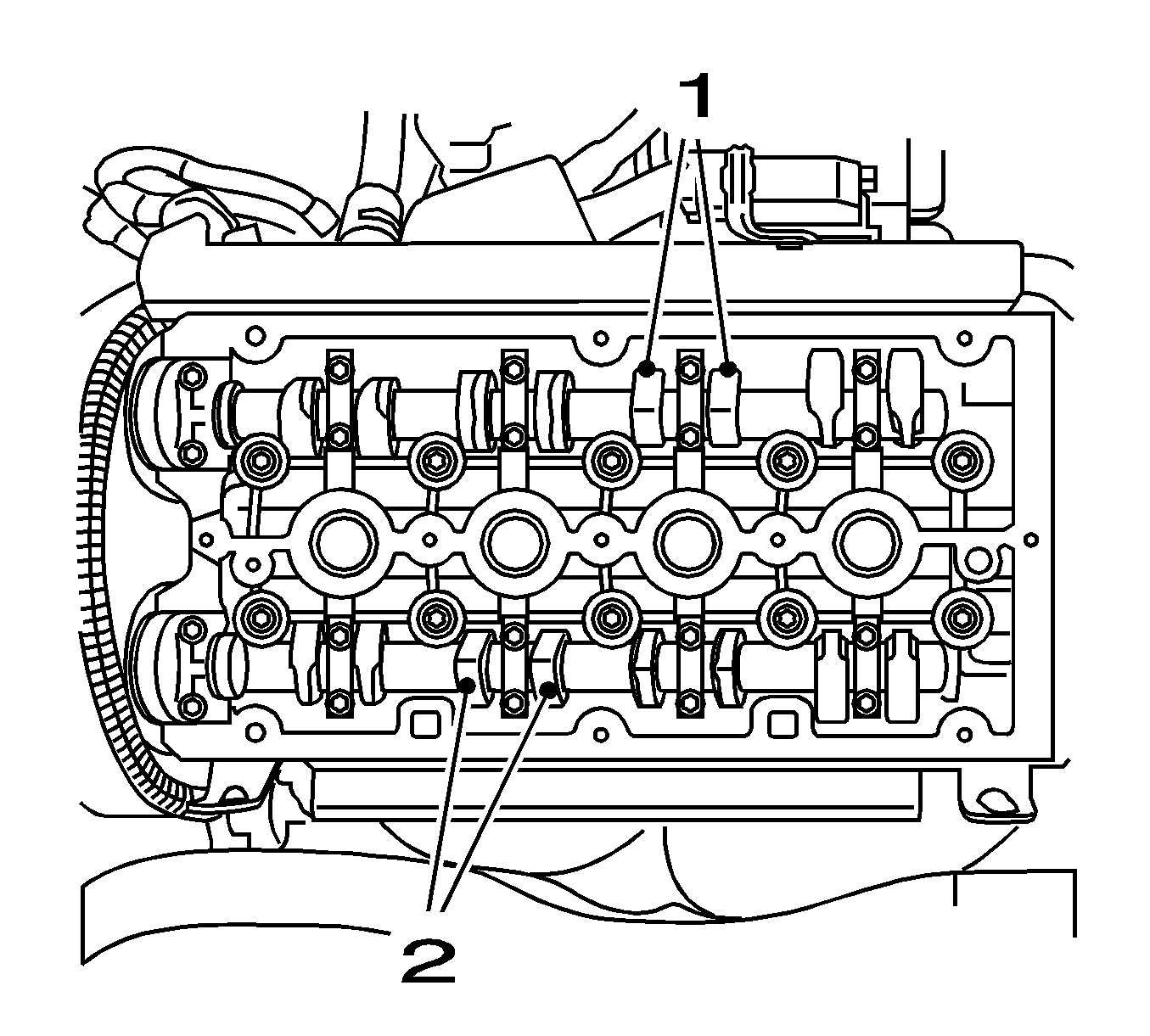
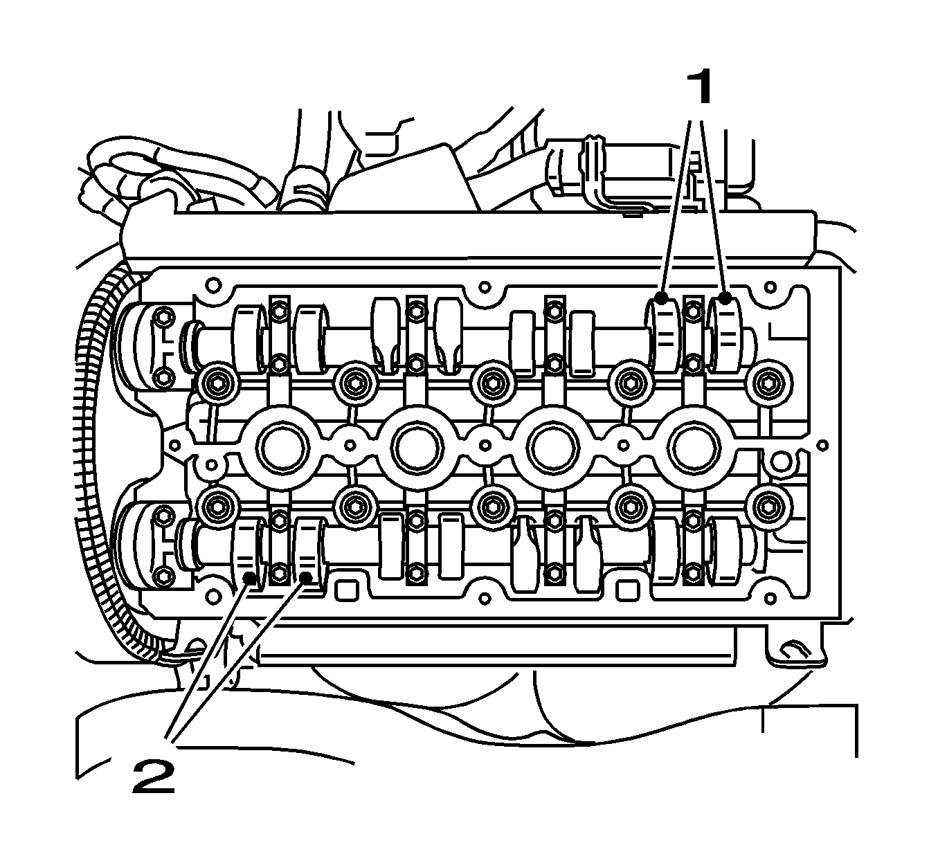
- Turn the crankshaft through 180 degrees.
| • | In the direction of the engine rotation |
| • | Pairs of cams (1) and (2) point upwards at an angle. |

- Inspect the 4 valves.
| • | Inspect valve lash with
KM-6361 (1). |
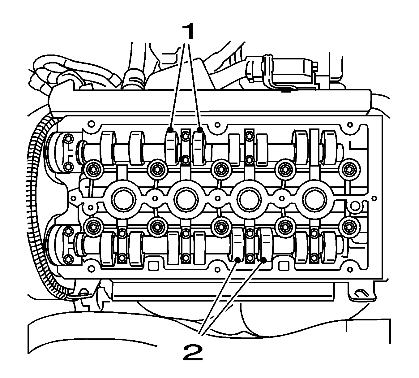
- Turn the crankshaft through 180 degrees.
| • | In direction of engine rotation |
| • | Pairs of cams (1) and (2) point upwards at an angle. |

- Inspect the 4 valves.
| • | Inspect valve lash with
KM-6361 (1). |
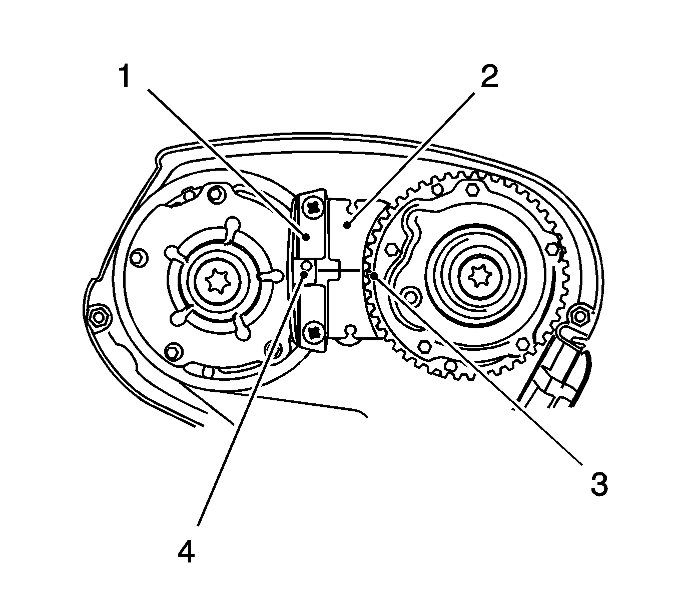
- Turn the crankshaft through 180 degrees.
| • | In direction of engine rotation |
| • | Pairs of cams (1) and (2) point upwards at an angle. |

- Inspect the 4 valves.
| • | Inspect valve lash with
KM-6361 (1). |
- Insert
MK-6340 into camshaft timing gears.
| • | Insert
MK-6340 (1, 2) in the camshaft adjuster as shown. |
| | Note: The spot-type marking (4) on the intake camshaft adjuster does not correspond to the groove of
MK-6340 during this process but must be somewhat above as shown.
|
| • | The spot type marking (3) on the exhaust camshaft adjuster must correspond to the groove on
MK-6340 . |
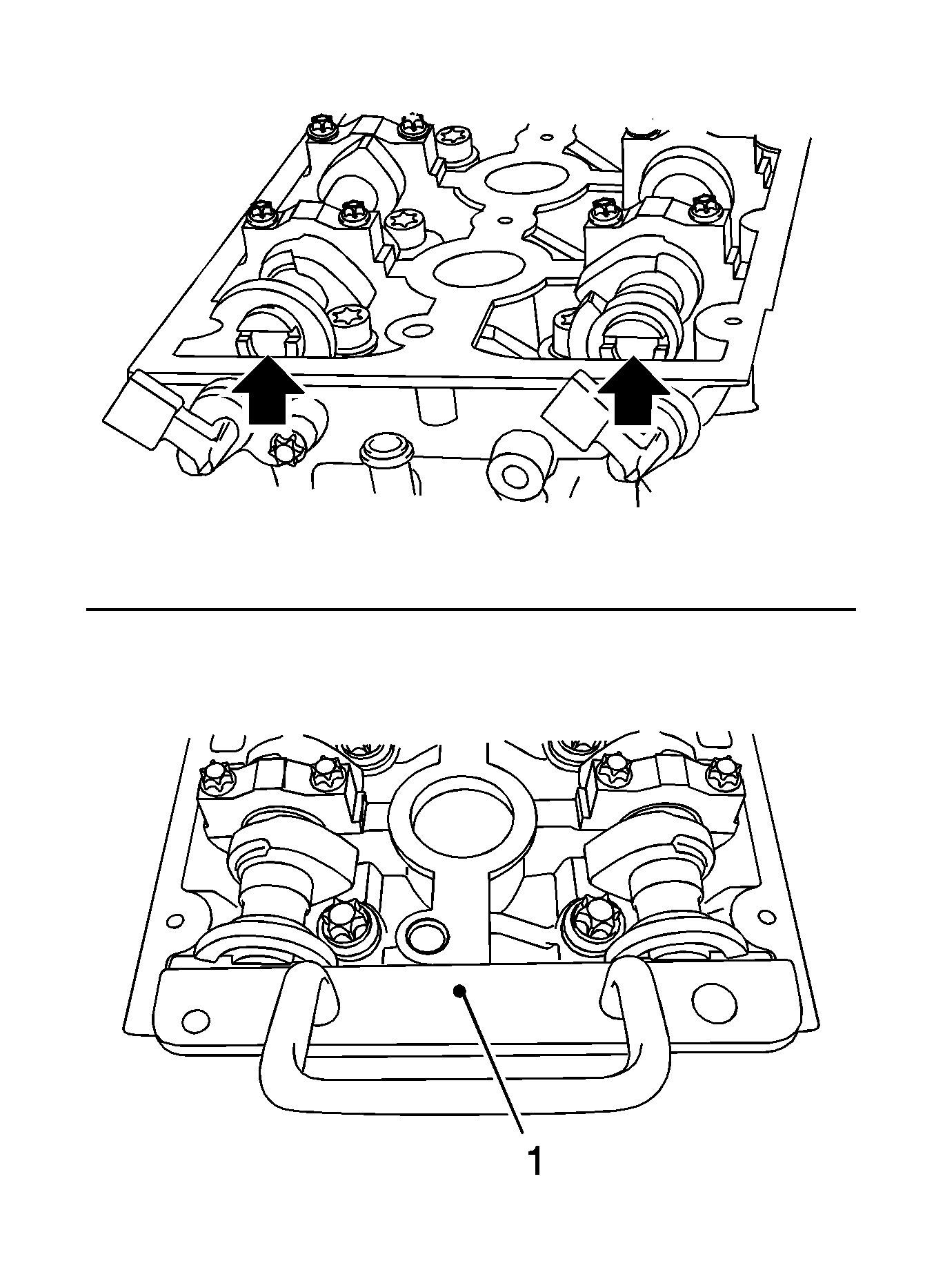
Note: If
MK-6628 cannot be inserted, the timing must be set.
- Insert
MK-6628 (1) into the camshafts.
Align the camshafts horizontally by the hexagon (arrows) until
MK-6628 can be inserted in both camshafts.
- Raise the vehicle by its full height.
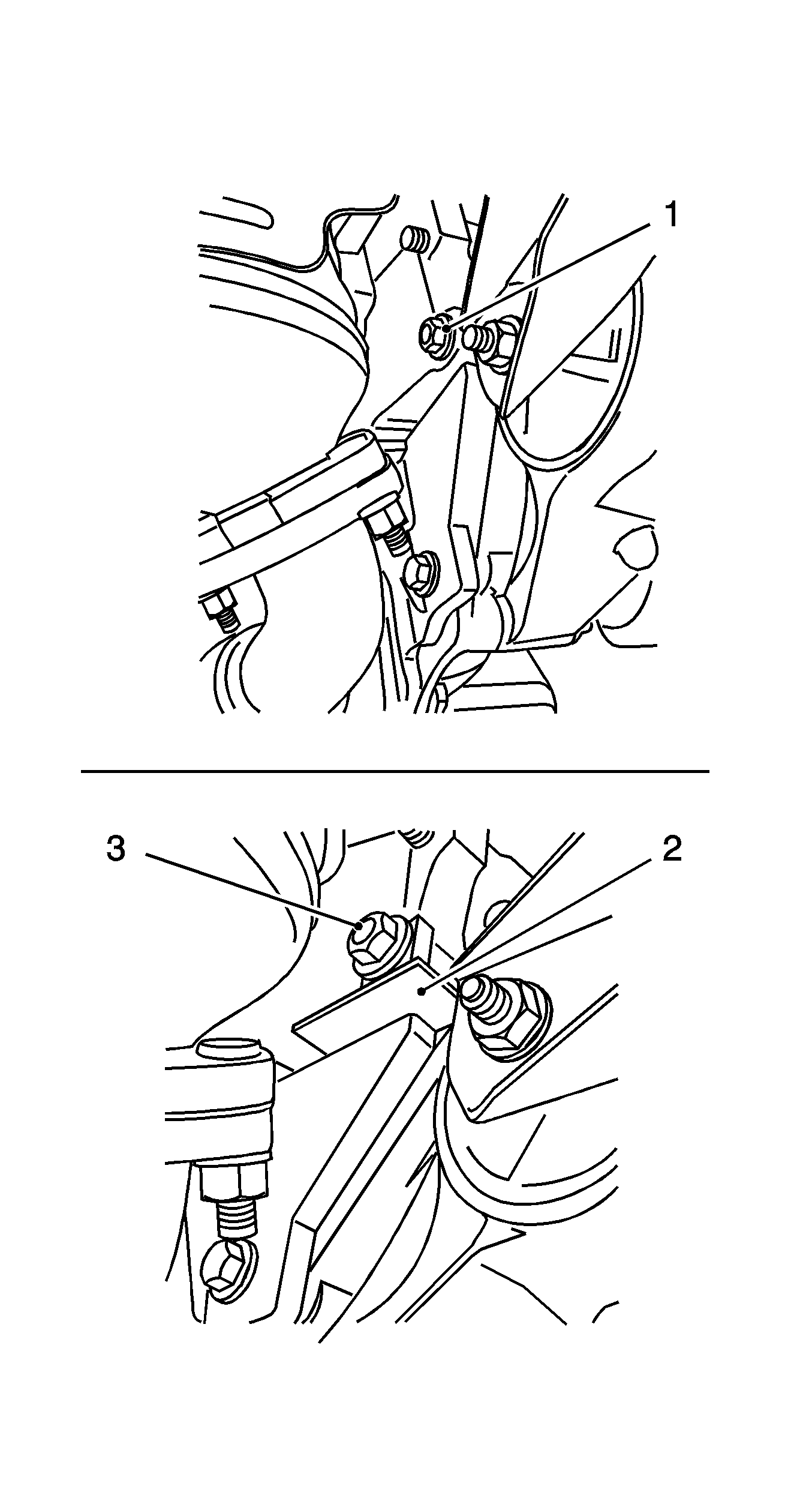
- Block the crankshaft.
Attach
KM-6625 .
| • | Detach the screwed connection (1). |
| • | Tighten the screwed connection (3). |
- Remove the torsional vibration damper.
Remove the bolt.
- Remove the front toothed belt cover (bottom).
Remove the 4 bolts.
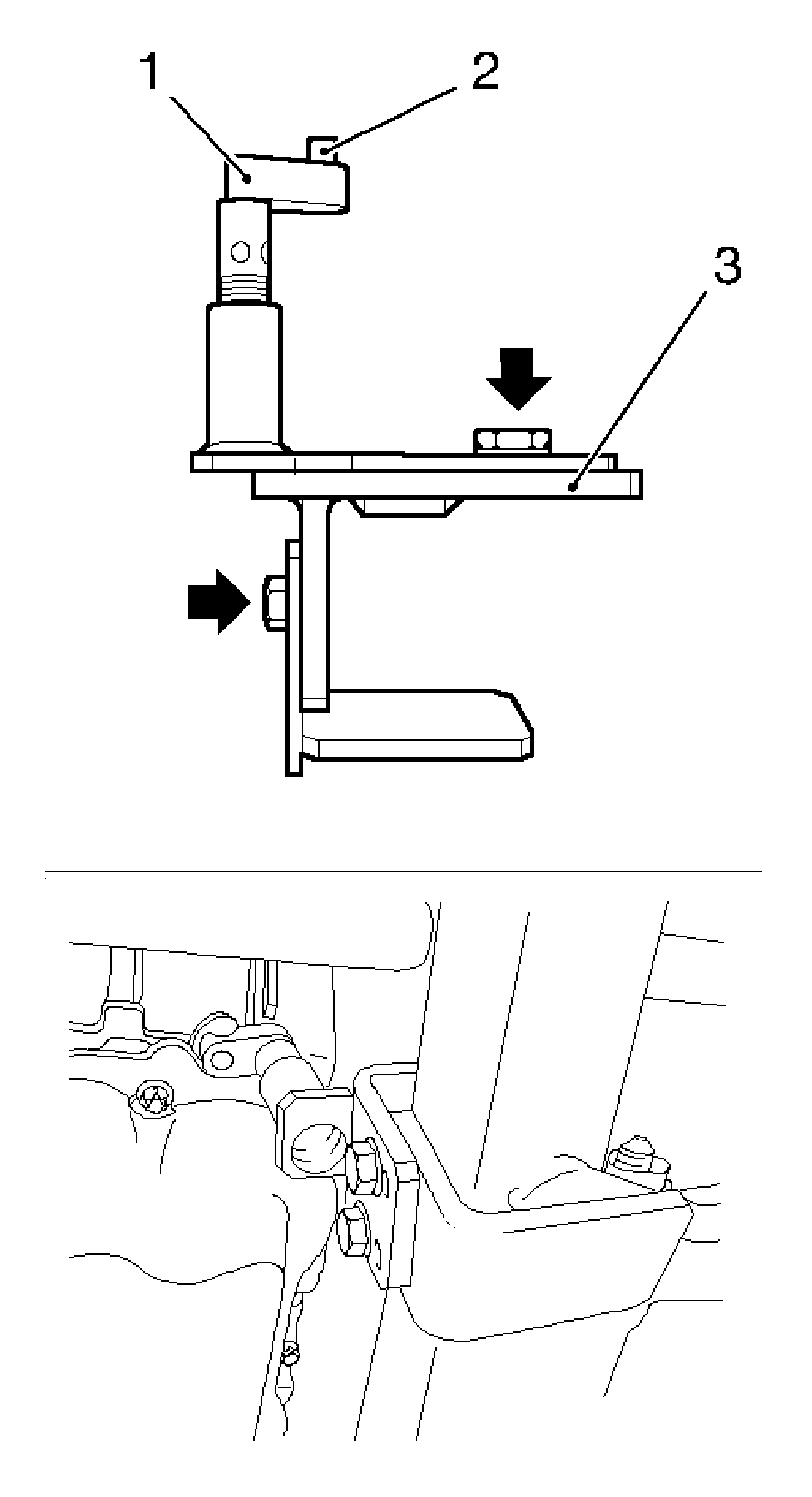
- Insert KM-6173 (3).
| • | Loosen the 4 bolts (arrows) and hand-tighten. |
| • | Align KM-6173 at the frame. |
| • | Position the support bearing (1). |
| • | Journal (2) must sit in the mount at the cylinder block. |
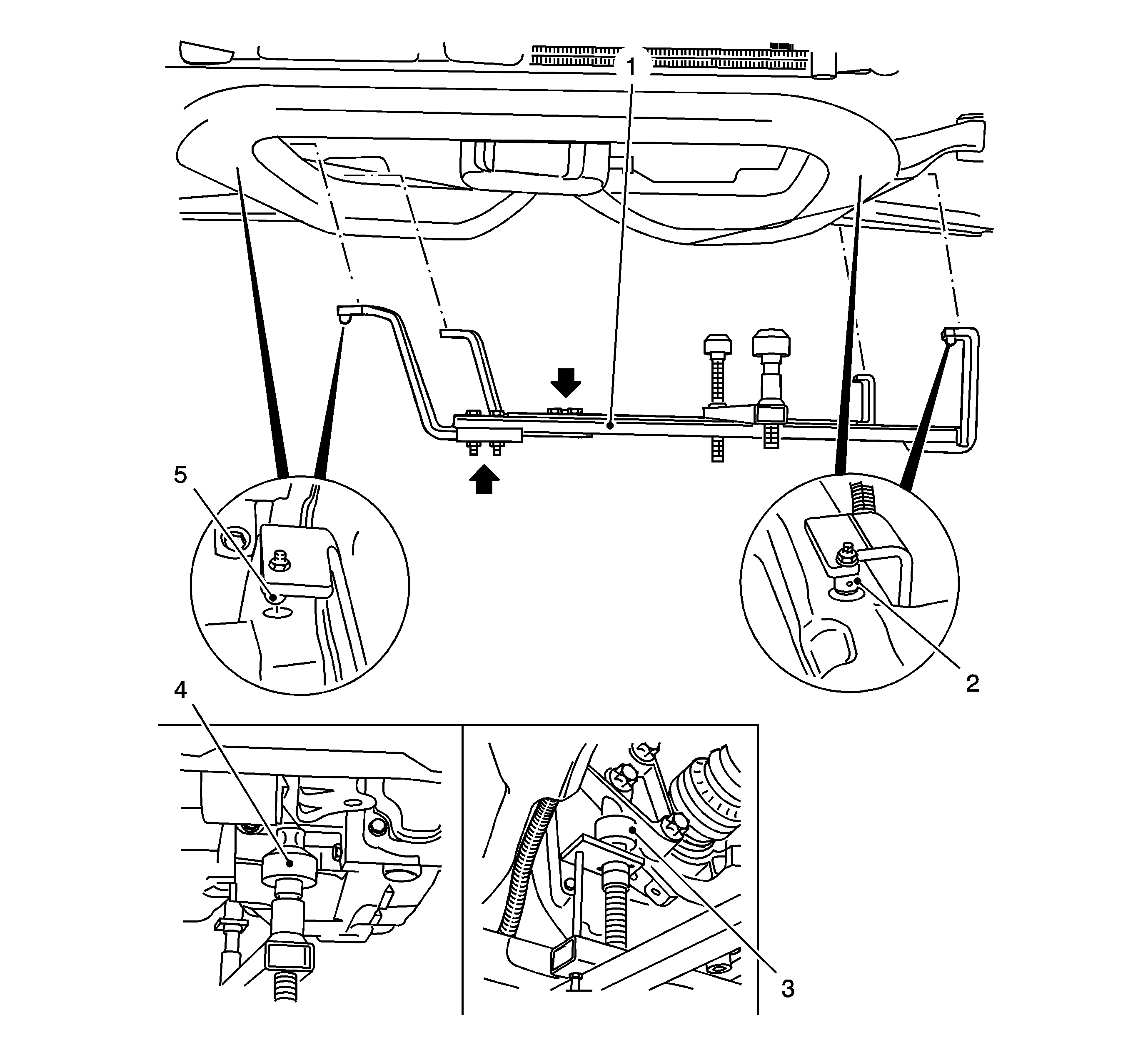
- Attach
KM-6001-A (1).
| • | Loosen the 3 bolts (arrows) in adjusting rails. |
| • | The journals (2, 5) must sit in the guide holes of the frame. |
| • | Tighten the 3 bolts in adjusting rails. |
| • | Adjust the support bearings, front (4) and rear (3). |
| | Note: The guide journals must be seated free from play in the support bearings.
|
| • | Raise the support bearings up to the stop on the guide journals. |
- Lower the vehicle by its full height.
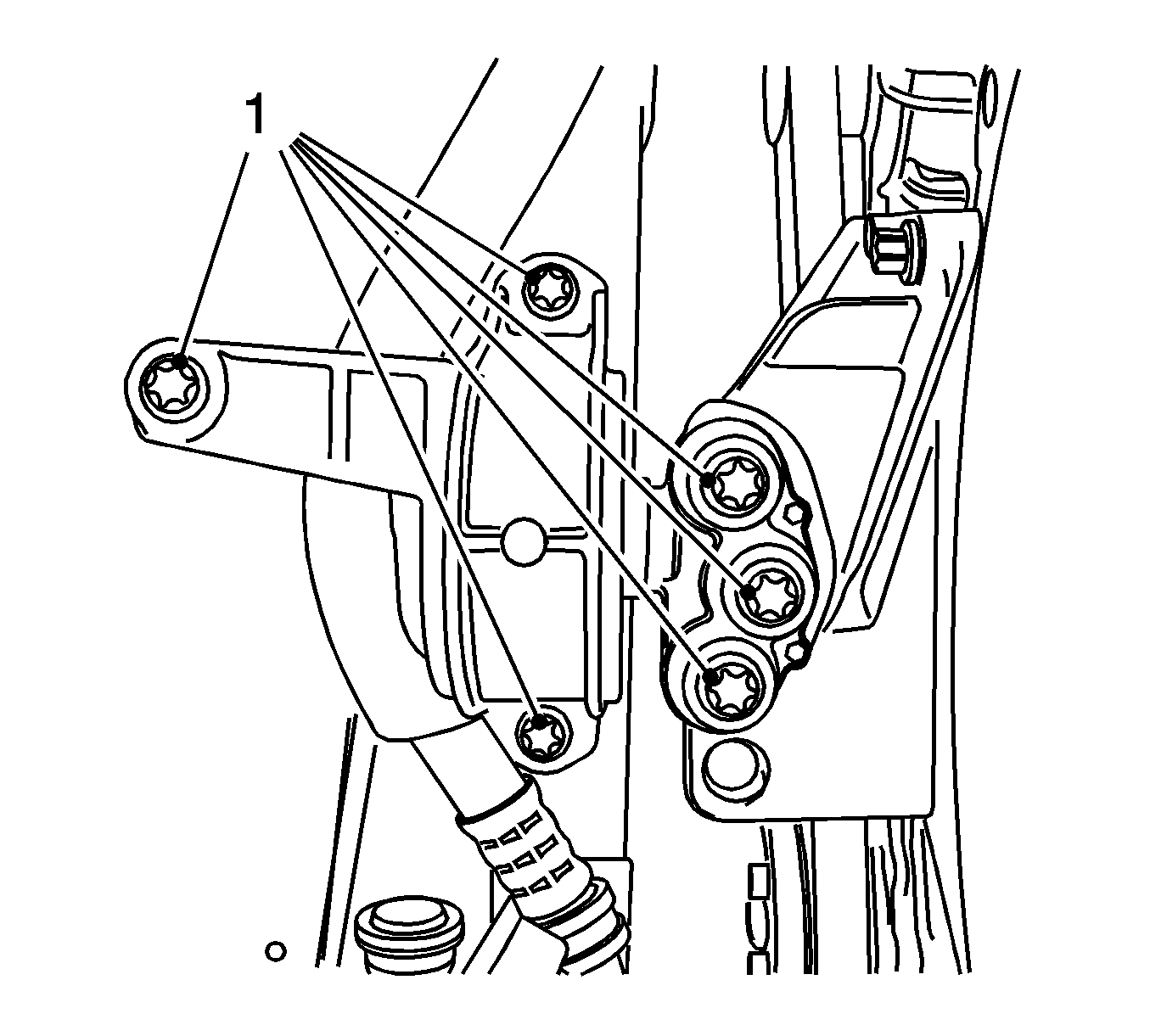
- Remove the engine damping block, right hand side.
Remove the 6 bolts (1).
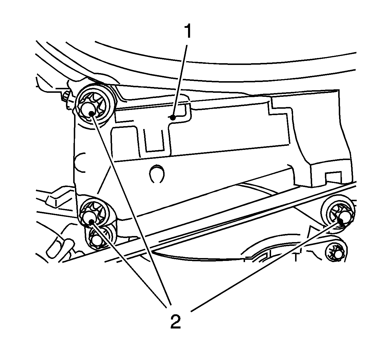
- Remove the engine damping block support (1).
Remove the 3 bolts (2).
- Remove the front toothed belt cover (center).
Disconnect 2x from rear of toothed belt cover.
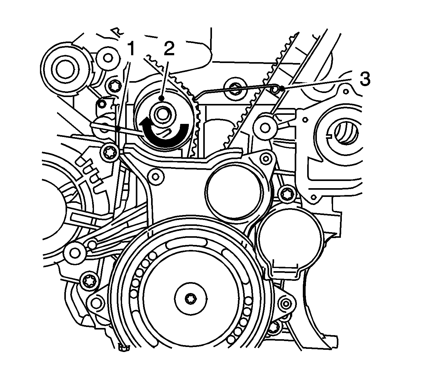
- Block the toothed belt tensioner.
Apply tension to the toothed belt tension roller (2) in the direction of the arrow, using an Allen key (1) and fix using
KM-6333
(3).
- Remove the toothed belt.
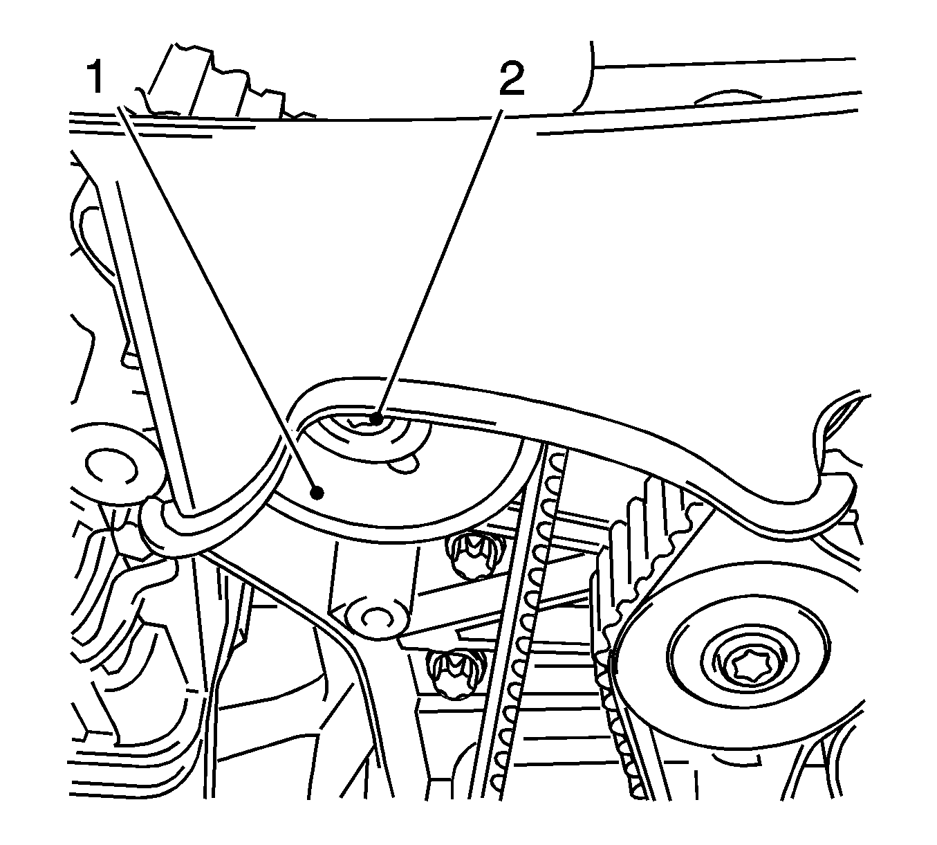
- Remove the toothed belt tensioner (1).
Remove the bolt (2).
- Raise the vehicle by its full height.
- Remove
KM-6625 .
Detach the screwed connection.
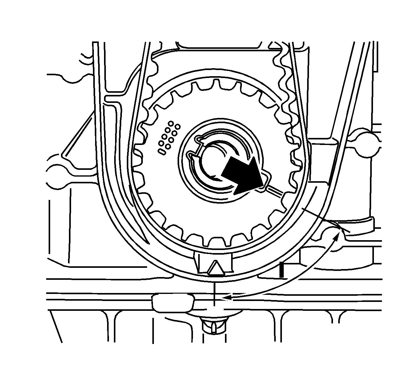
- Turn the crankshaft 60 degrees against the direction of engine rotation.
- Lower the vehicle by its full height.
- Place the collecting basin underneath.
- Remove the closure bolt, exhaust camshaft adjuster.
- Remove the intake camshaft closure bolt.
- Remove
MK-6340 .
- Loosen the exhaust camshaft adjuster.
Counterhold at camshaft hexagon.
- Remove the exhaust camshaft adjuster.
Remove the bolt.
- Loosen the intake camshaft adjuster.
Counterhold at camshaft hexagon.
- Remove the intake camshaft adjuster.
Remove the bolt.
- Remove the rear toothed belt cover.
| • | Disconnect the wiring trough cover. |
- Remove
MK-6628 .
Counterhold at hexagon of camshafts.
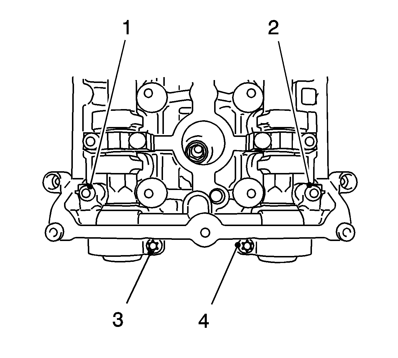
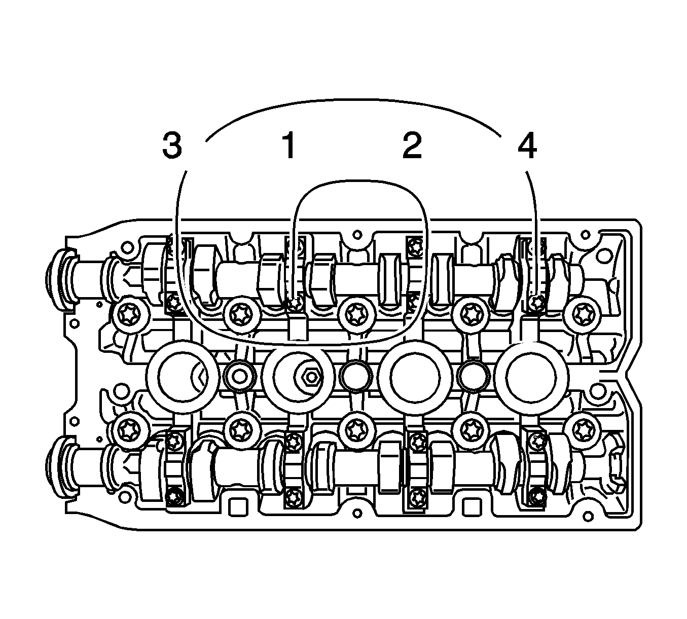
- Remove the 1st camshaft bearing support.
| • | Note removal sequence 1-4. |
| • | Release the bearing support by striking it gently with a plastic hammer. |
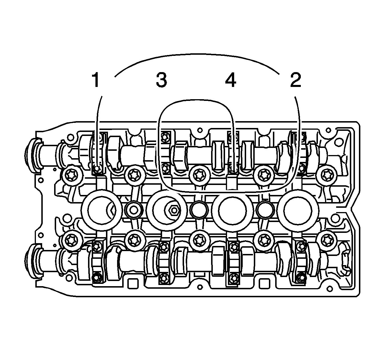
Note: Mark the camshaft bearing caps before removing them.
- Remove the intake camshaft.
| • | Detach camshaft bearing caps 2-5 working from outside to inside in a spiral in steps of 1/2 up to 1 turn. |
| | Note: Note the marking on the camshaft bearing cover with stamped numbers from 1 to 0 (there is a dot at bottom left before each number to avoid mistakes)
|
| • | Remove the camshaft bearing cover from the cylinder head and take out the camshaft. |
Note: Mark the camshaft bearing caps before removing them.
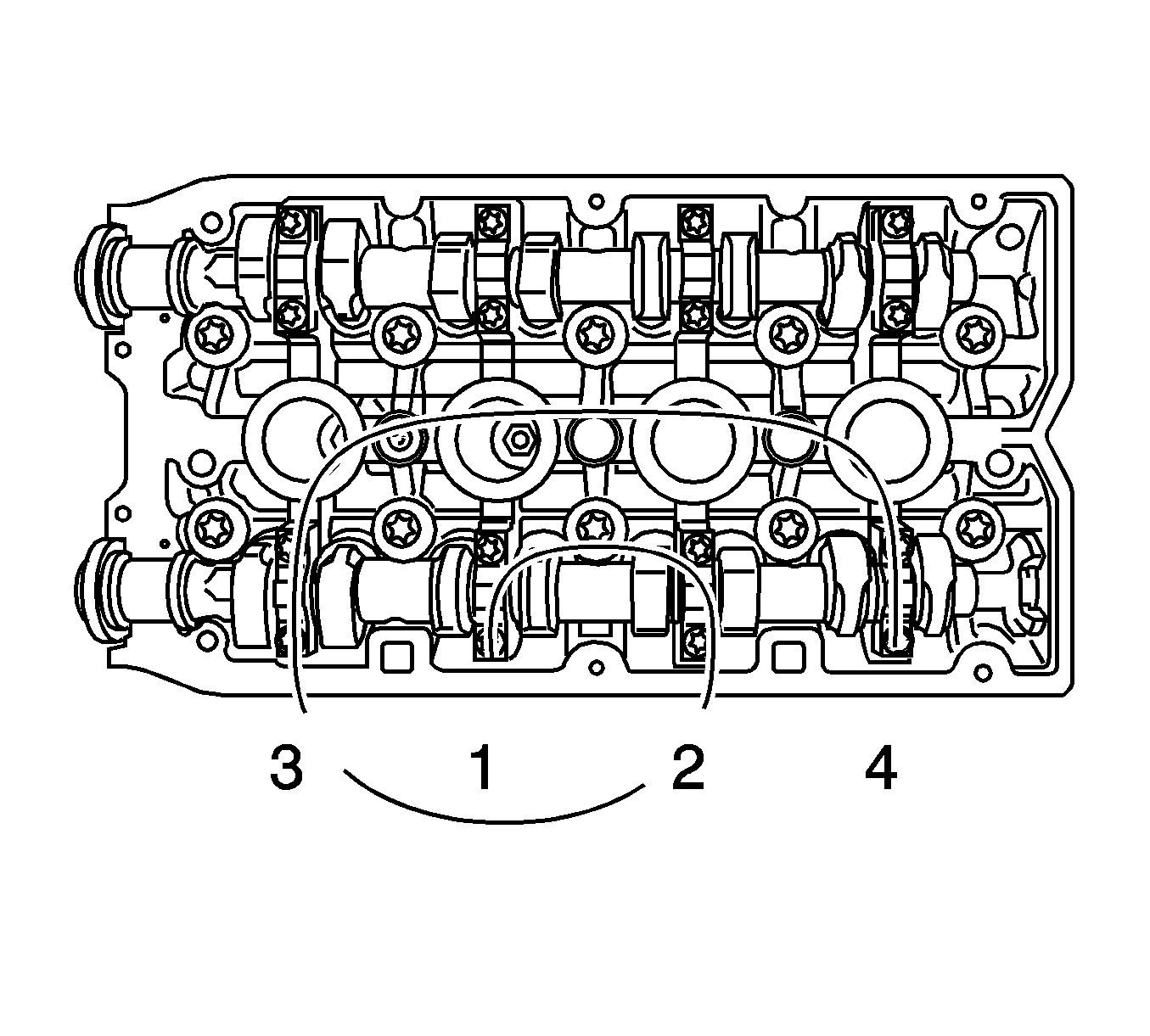
- Remove the exhaust camshaft.
| • | Detach camshaft bearing caps 2-5 working from outside to inside in a spiral in steps of 1/2 up to 1 turn. |
| | Note: Note the marking on the camshaft bearing cover with stamped numbers from 1 to 0 (there is a dot at bottom left before each number to avoid mistakes).
|
| • | Remove the camshaft bearing cover from the cylinder head and take out the camshaft. |
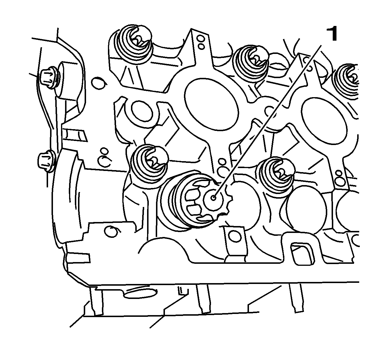
- Remove the cup tappet with
KM-845 (1).
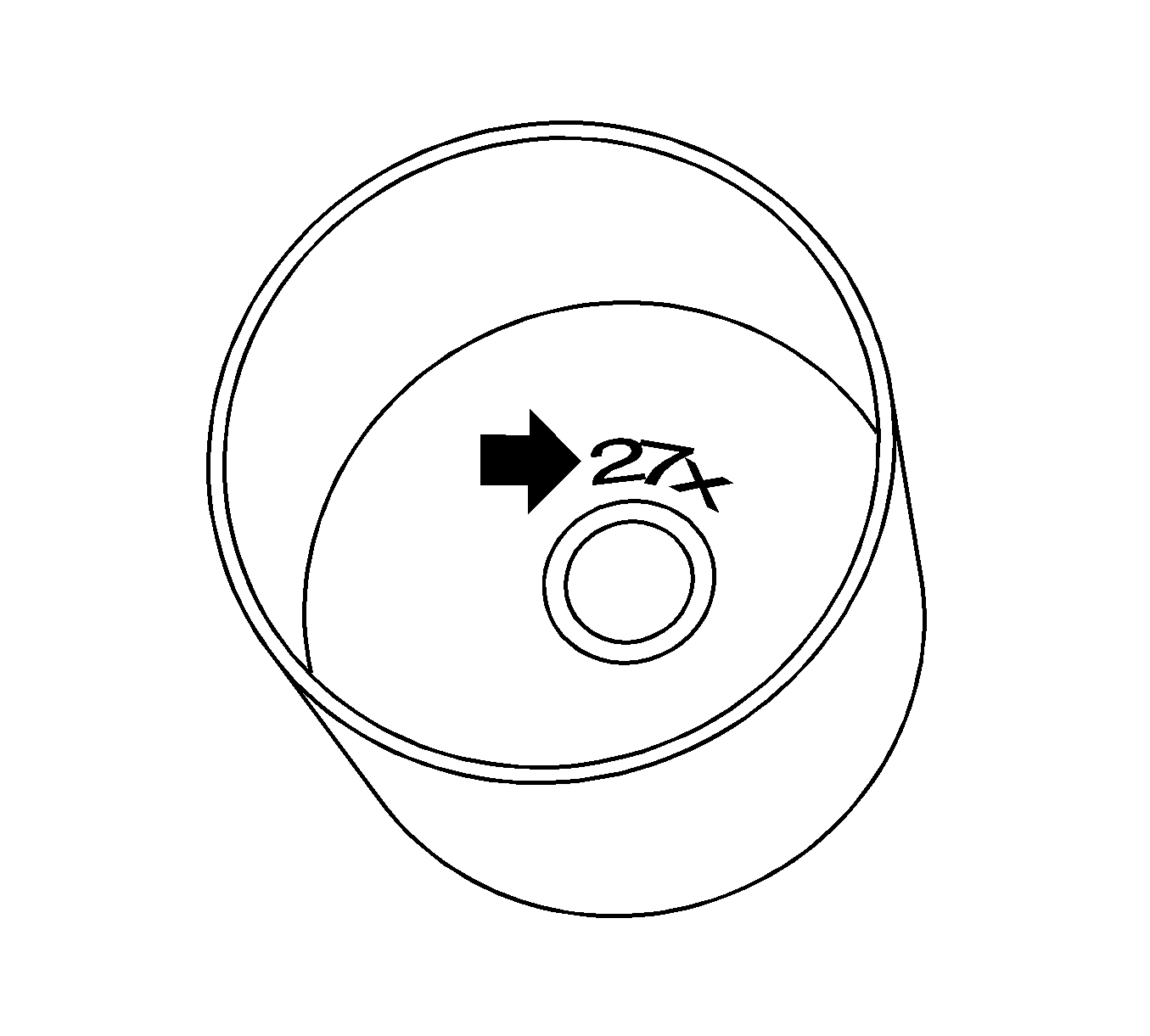
- Determine cup tappet size.
Example of determining the size of a cup tappet, intake side:
| • | Dimension of fitted cup tappet 3.20 mm (Identification number 20) |
| • | Measurement between cams and cup tappets + 0.31 mm = 3.51 mm |
| • | Required value, valve lash, intake side -0.25 mm |
| | Note: The identification number (arrow) is on the inside of the cup tappet.
|
| • | Nominal dimension of the new cup tappet 3.265 mm (Identification number 27x) |
| • | Now use a cup tappet with this dimension or one that is nearest to it. |
- Insert the cup tappet with
KM-845 .
Lightly coat sliding surfaces with oil.
Caution: Refer to Fastener Caution in the Preface section.
- Install the intake camshaft.
| • | Coat with MoS 2 lubricating paste. |
| | Note: Note the identification marking on the camshaft bearing cover.
|
| • | Install the camshaft bearing cover. |
| • | Tighten the camshaft bearing caps 2-5 in a spiral from the inside to the outside. |
Tighten
Tighten the camshaft bearing caps to 8 N·m (70 lb in).
- Install the exhaust camshaft.
| • | Coat with MoS 2 lubricating paste. |
| | Note: Note the identification marking on the camshaft bearing cover.
|
| • | Install the camshaft bearing cover. |
| • | Tighten the camshaft bearing caps 2-5 in a spiral from the inside to the outside. |
Tighten
Tighten the camshaft bearing caps to 8 N·m (70 lb in).
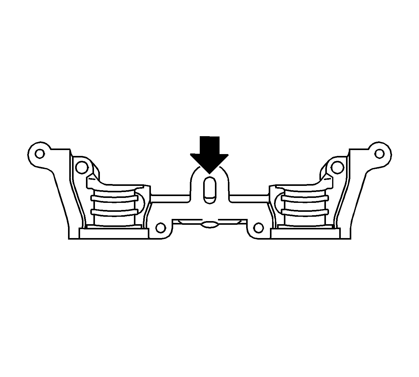
Note: Sealing surfaces must be free from oil and grease.
- Clean sealing surfaces of 1st camshaft bearing support and the cylinder head with a suitable tool, e.g. plastic wedge.
Clean the oil duct (arrow) from any sealant residue.
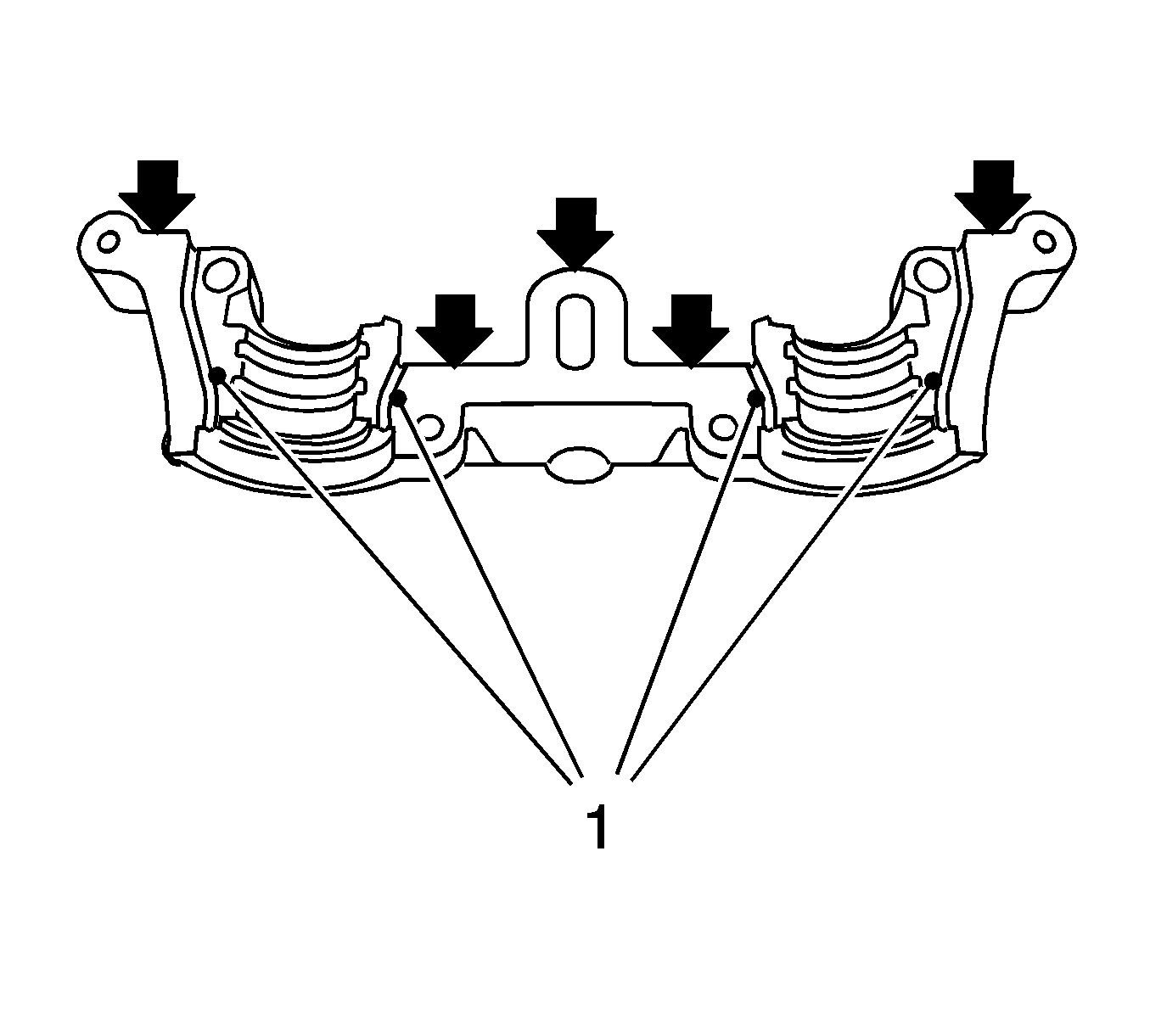
Note:
| • | It is essential to ensure that no sealant is applied outside the marked sealing areas. |
| • | The grooves (1) adjacent to the sealing surfaces must remain free from sealant. |
- Apply surface sealant (green) to the sealing surfaces (arrows) of the 1st camshaft bearing support thinly and evenly.
- Position the camshaft bearing bridge on the cylinder block and tighten the bolts hand tight, approximately 2 N·m (18 lb in).
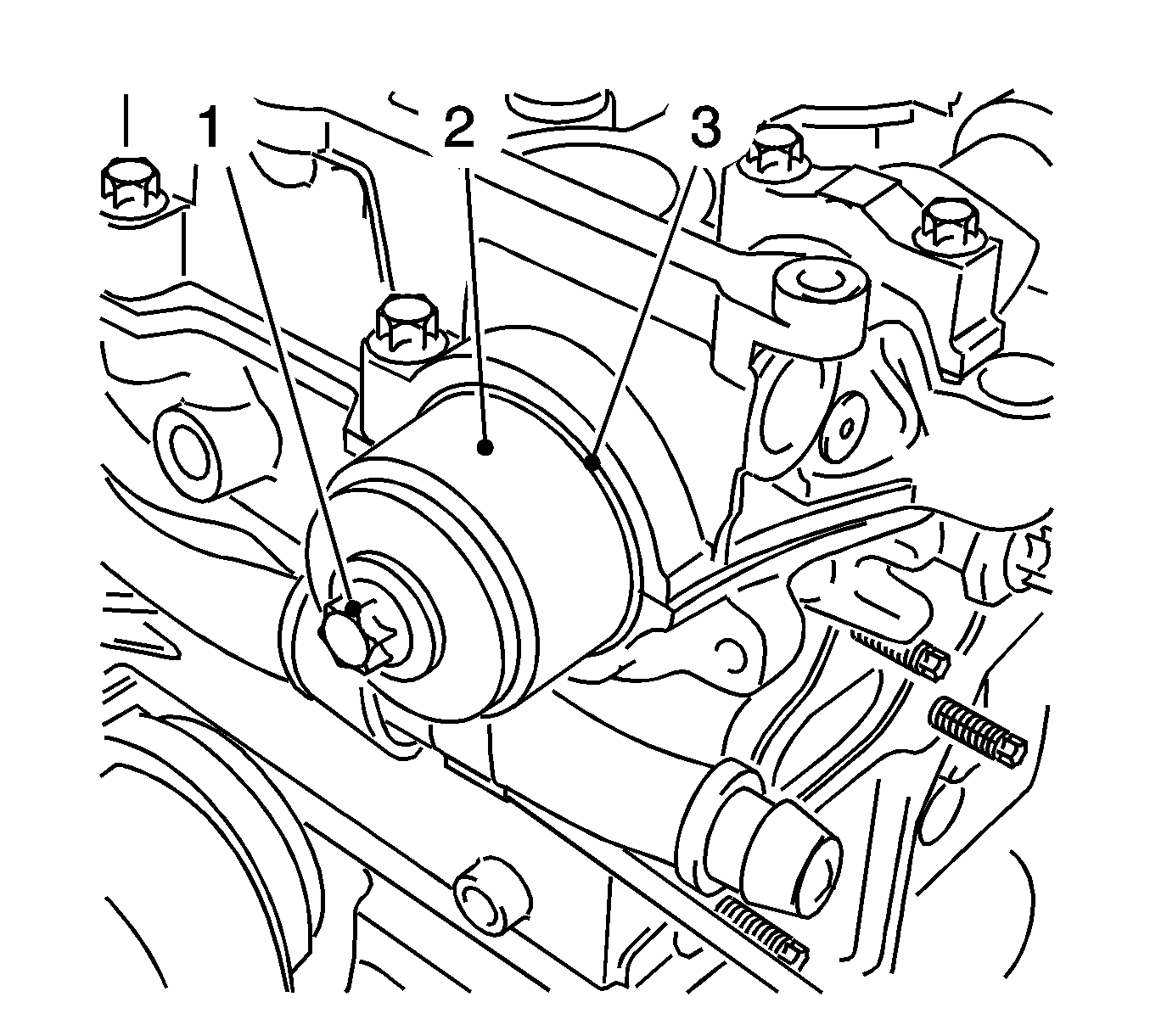
- Install the 2 camshaft seal rings.
| • | Tighten the seal ring with
KM-422 (4) on the camshaft until this is in contact with the cylinder head (arrow). |
| | To install, use a camshaft sprocket bolt (1) in conjunction with shims (2)
with a total thickness of approximately 10 mm. |
Note: No sealant may reach the camshafts.
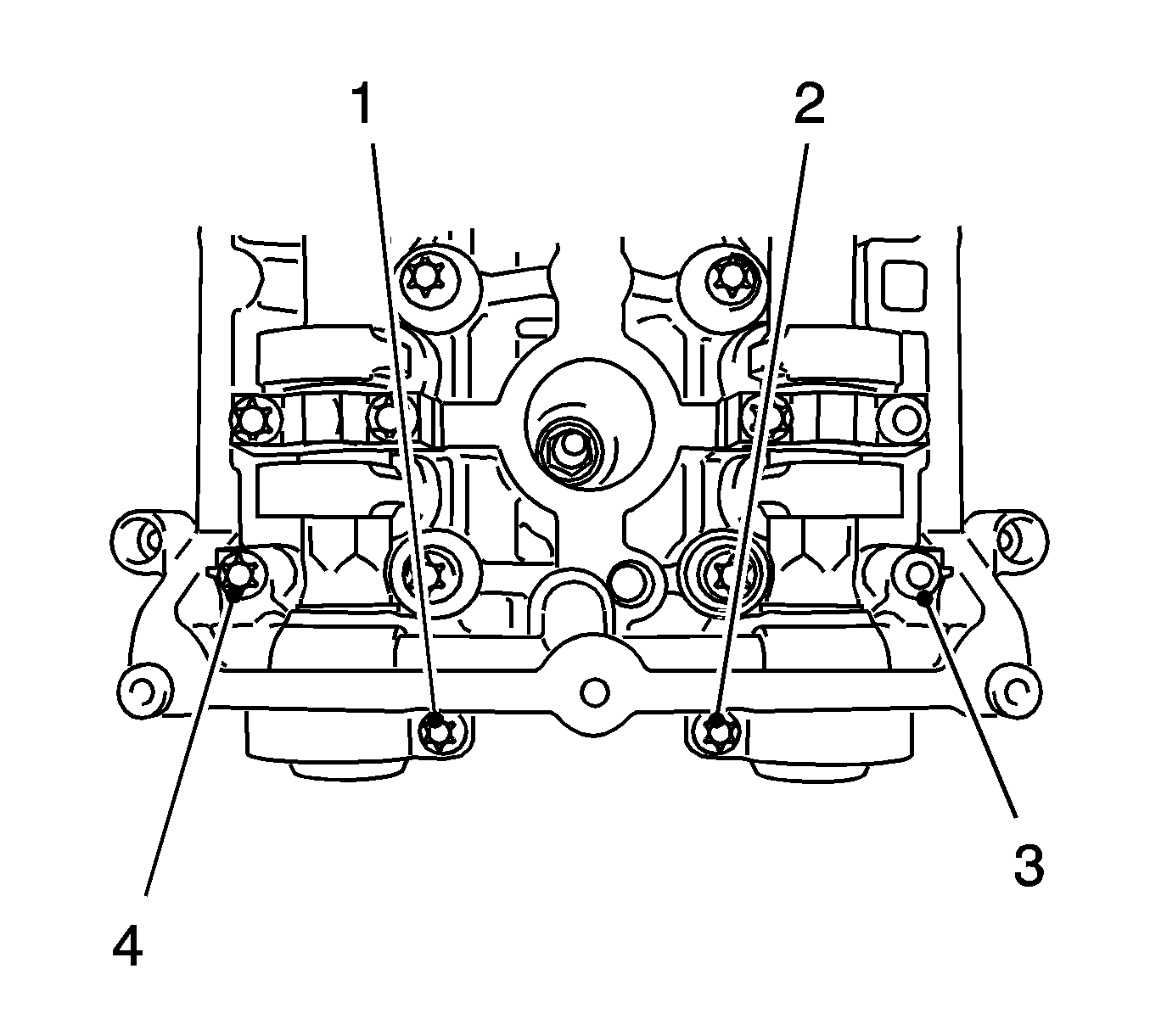
- Attach 1st camshaft bearing support.
| • | Place the bearing support in position. |
Tighten
Tighten the 4 bolts to 8 N·m (70 lb in).
| • | Note installation sequence 1-4. |
- Install the intake camshaft seal ring with
KM-422 .
| • | Push the seal ring into the camshaft bearing cover with
KM-422 (1). |
| • | Use the bolt (2) and the washer (3) of the camshaft adjuster. |
- Clean the 4 threads, rear toothed belt cover.
- Install the rear toothed belt cover.
| • | Tighten the 4 new bolts. |
Tighten
Tighten the 4 new bolts to 6 N·m (53 lb in).
| • | Coat the 4 bolts with locking compound (red). |
| • | Clip in the wiring trough cover. |
- Attach the exhaust camshaft adjuster.
| • | Insert the new sealing sleeve in the adjuster. |
- Attach the intake camshaft adjuster.
| • | Insert the new sealing sleeve in adjuster. |
Note: Note markings on the camshaft sprockets.
- Insert
MK-6340 .
- Fasten the exhaust camshaft adjuster.
Tighten
Tighten the bolt to 65 N·m (48 lb ft) plus 125 degrees plus 15 degrees.
- Counterhold at camshaft hexagon.
- Fasten the intake camshaft adjuster.
Tighten
Tighten the bolt to 65 N·m (48 lb ft) plus 125 degrees plus 15 degrees.
- Counterhold at camshaft hexagon.
- Tighten the exhaust camshaft adjuster closure bolt.
Tighten
Tighten the exhaust camshaft adjuster closure bolt to 30 N·m (22 lb ft).
- Replace seal ring.
- Tighten the closure bolt, intake camshaft adjuster.
Tighten
Tighten the closure bolt, intake camshaft adjuster to 30 N·m (22 lb ft).
- Replace seal ring.
- Remove
MK-6628 .
- Raise the vehicle by its full height.
- Set the crankshaft to cylinder number 1 ignition TDC (1).
Marking, toothed belt drive gear and oil pump housing adapter must align.
- Block the crankshaft.
| • | Install the bolted connection. |
- Lower the vehicle by its full height.
- Clean the thread, toothed belt tensioner.
- Insert
KM-6625 .
| • | Install the bolted connection. |
| • | Released leg of spring (1) of the toothed belt tension roller must engage in the cut-out (arrow) of the pump module. |
Tighten
Tighten the bolt to 20 N·m (15 lb ft).
Note: Use the assembly tool.
- Insert the toothed belt.
- Release tension on the toothed belt tensioner.
| • | Apply preliminary tension clockwise to the toothed belt tension roller. |
- Raise the vehicle by its full height.
- Install the front toothed belt cover (lower).
Tighten
Tighten the 4 bolts to 6 N·m (53 lb in).
Note: New bolt must be coated with screw locking compound (red).
- Install the torsional vibration damper.
Tighten
Tighten the new bolt to 95 N·m (70 lb ft) plus 30 degrees plus 15 degrees.
- Remove
KM-6625 .
| • | Detach the screwed connection. |
| • | Tighten the bolted connection. |
- Lower the vehicle by its full height.
- Remove
MK-6340 .
- Inspect position of the camshaft sprockets.
| | Note: Note marking, camshaft sprockets.
|
| • | Turn the crankshaft 720 degrees in the direction of engine rotation by the bolt on the torsional vibration damper. |
| • | Insert
MK-6340 into the camshaft timing gears. |
- Inspect the camshaft positions.
- Insert the front toothed belt cover (center).
Insert
MK-6628 in the camshafts, align the camshafts by hexagon until
MK-6628 can be inserted in both
camshafts, clip in 2x to the rear toothed belt cover.
- Install the support for engine damping block.
Tighten
Tighten the 3 bolts to 50 N·m (37 lb ft).
- Install the engine damping block.
| • | Fasten the engine bracket adapter. |
Tighten
Tighten the 3 bolts to 55 N·m (40 lb ft).
| • | Fasten the engine damping block. |
Tighten
| • | Tighten the 2 bolts to 55 N·m (40 lb ft). |
| • | Tighten the nut to 55 N·m (40 lb ft). |
- Raise the vehicle by its full height.
- Inspect the crankshaft position.
Marking on the torsional vibration damper must align with the marking on the lower part of the toothed belt cover.
- Remove
KM-6001-A .
Loosen the 3 screwed connections.
- Remove KM-6173.
Remove the 4 bolts.
- Clean the thread of bolt, drive belt tensioner.
- Install the drive belt tensioner. Refer to
Drive Belt Tensioner Replacement.
- Lower the vehicle by its full height.
- Remove
MK-6628 .
- Install the camshaft cover. Refer to
Camshaft Cover Replacement.
- Remove
MK-6340 .
Attach the bracket.
Tighten
Tighten the 2 bolts to 2.5 N·m (22 lb in).
- Install the front toothed belt cover (top). Refer to
Timing Belt Upper Front Cover Replacement.
- Install the air cleaner housing. Refer to
Air Cleaner Assembly Replacement.
- Connect the battery.
Attach the negative connection to the ground terminal.
Tighten
Tighten the nut to 5 N·m (44 lb in).
- For programming procedures, refer to
Control Module References.
- Close the hood.


