Special Tools
| • | J 45722 /KM-J-45722 Fuel Sender Lock Ring Wrench |
| • | SA9805E /KM-796-A Fuel Line Separator |
Removal Procedure
Note:
| • | The fuel tank must be drained with a suitable, commercially-available fuel removal unit and suction hose - follow safety regulations and national legislation. The fuel tank is fitted with a refill limit float valve. This is located on the filler
neck in the fuel tank. To prevent damaging the refill limit float valve, a suitable suction hose must be used. |
| • | In the presence of fuel vapors or escaping fuel - observe safety regulations and national legislation. Store drained fuel in a suitable, sealable container. |
- Open the hood.
Warning: Refer to Battery Disconnect Warning in the Preface section.
- Remove the battery.
| • | Disconnect the ground clamp from ground terminal. |
- Loosen the nuts on the right rear wheel.
- Raise the vehicle halfway.
- Remove the right rear wheel.
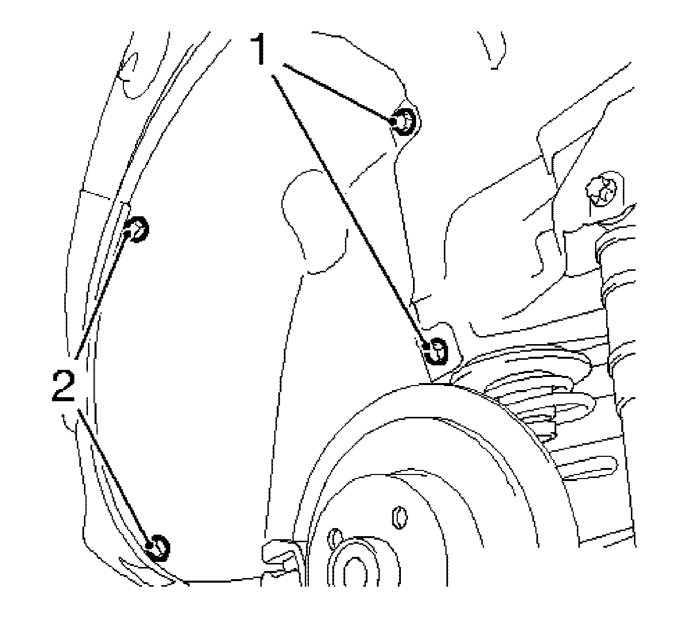
- Remove the wheel housing inner paneling, right rear.
| • | Remove the 2 bolts (2). |
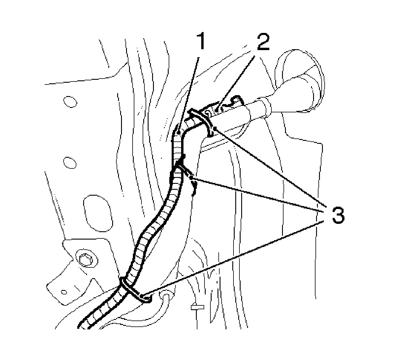
- Disconnect the wiring harness of the pressure sensor (atmospheric pressure) (1).
| • | Remove the wiring harness plug (2). |
| • | Remove the 3 cable ties (3). |
- Raise the vehicle halfway.
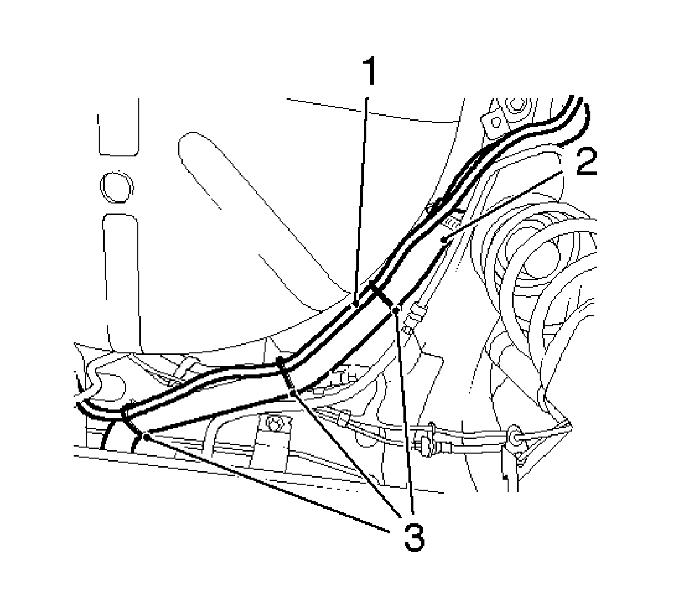
- Remove the wiring harness of the pressure sensor (atmospheric pressure) (1) from the fuel filler tube (2).
Remove the 3 cable ties (3).
- Remove the complete exhaust system. Refer to
Exhaust System Replacement.
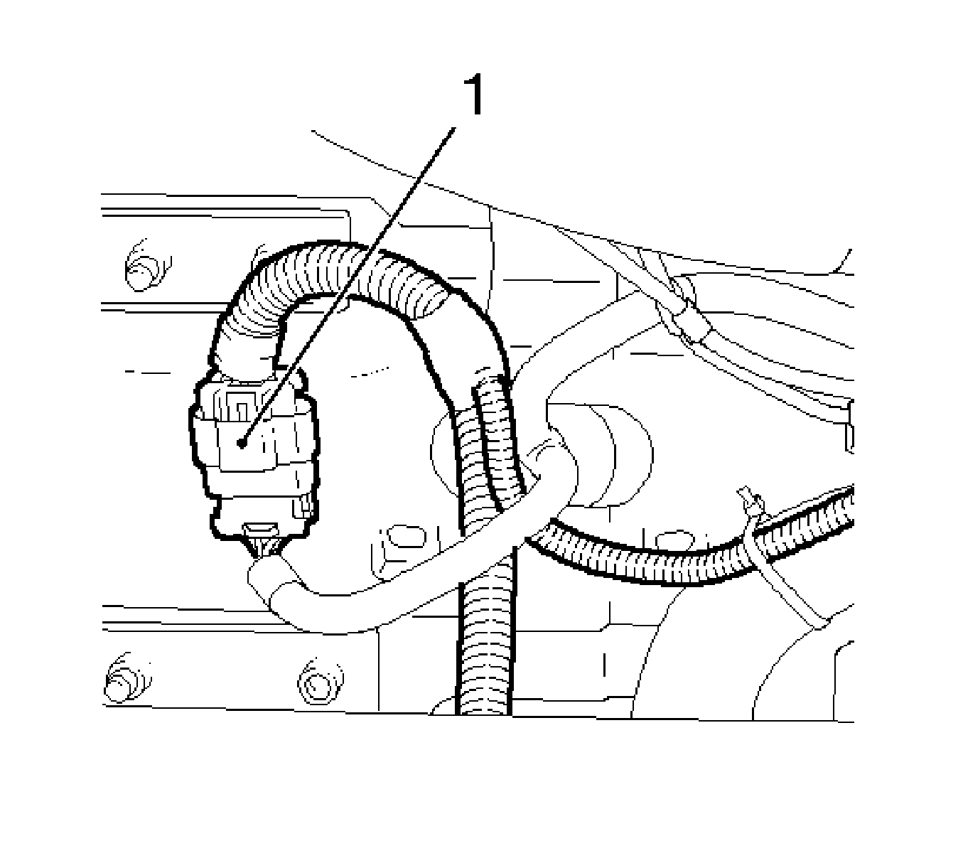
- Remove the wiring harness plug of the fuel tank fuel pump module (1).
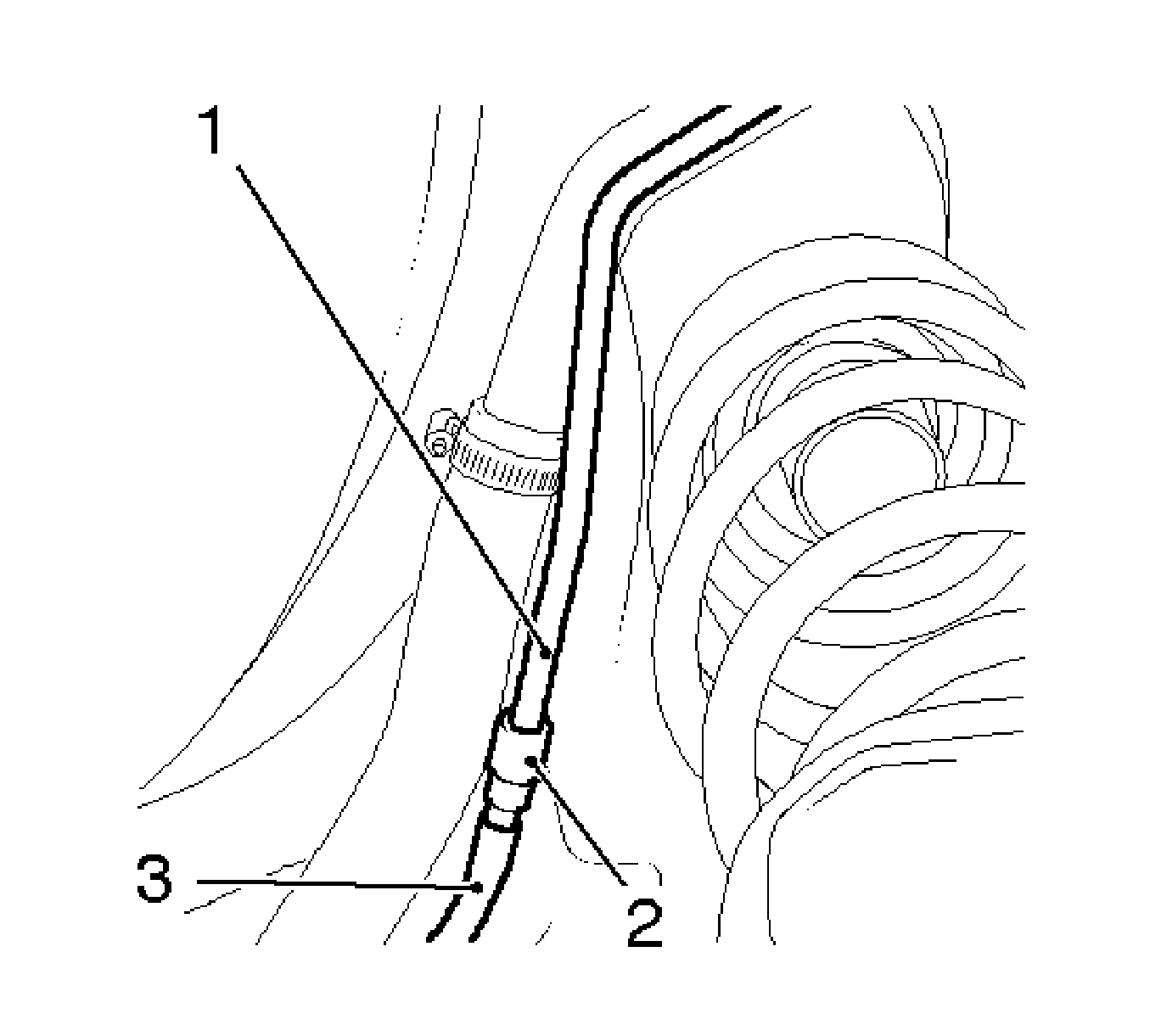
- Remove the vent hose (3) from the vent pipe (1).
Disconnect the quick-release fitting (2) using
SA9805E /KM-796-A.
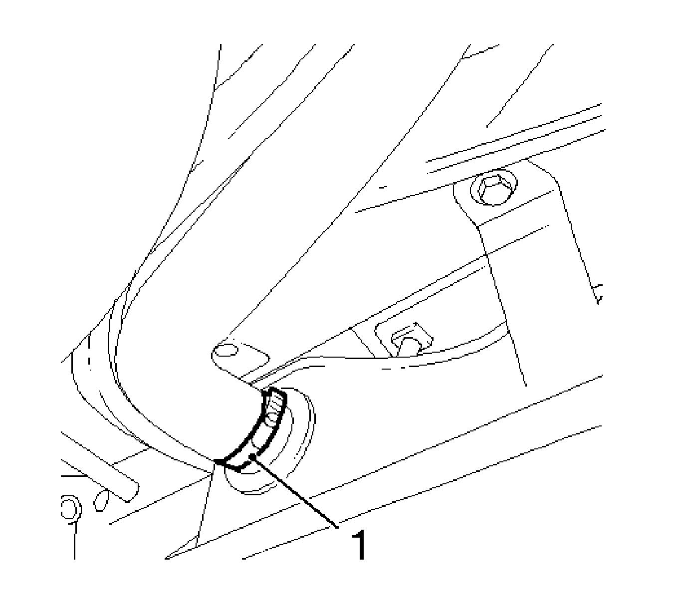
- Remove the fuel filler tube from the fuel tank.
Release the clamp (1).
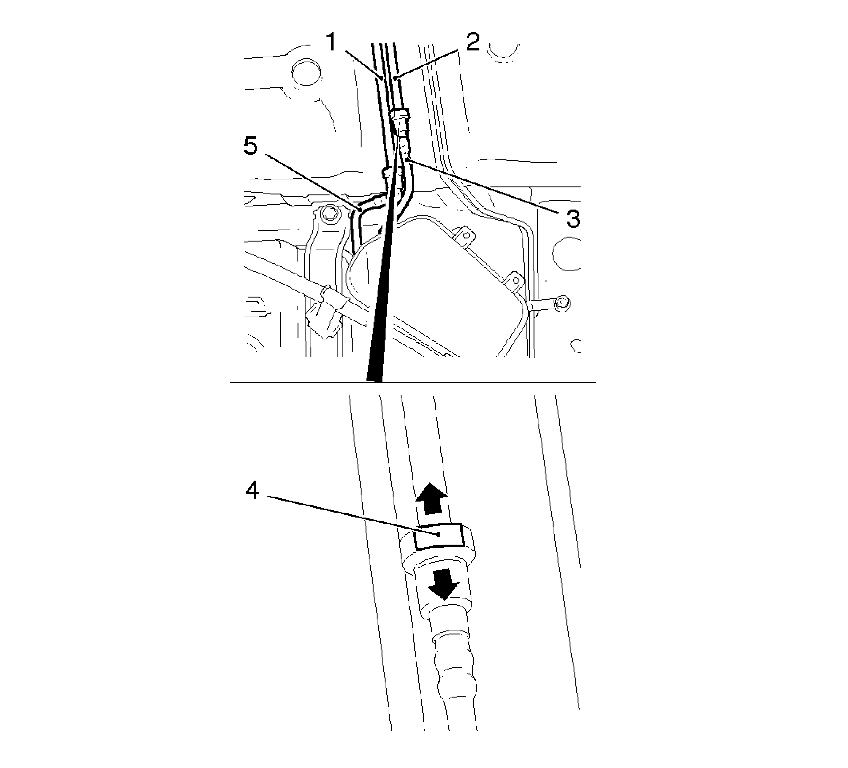
- Remove the rear fuel lines (3, 5) from the middle fuel lines (1, 2)
| • | Disconnect the 2 quick-release fittings. |
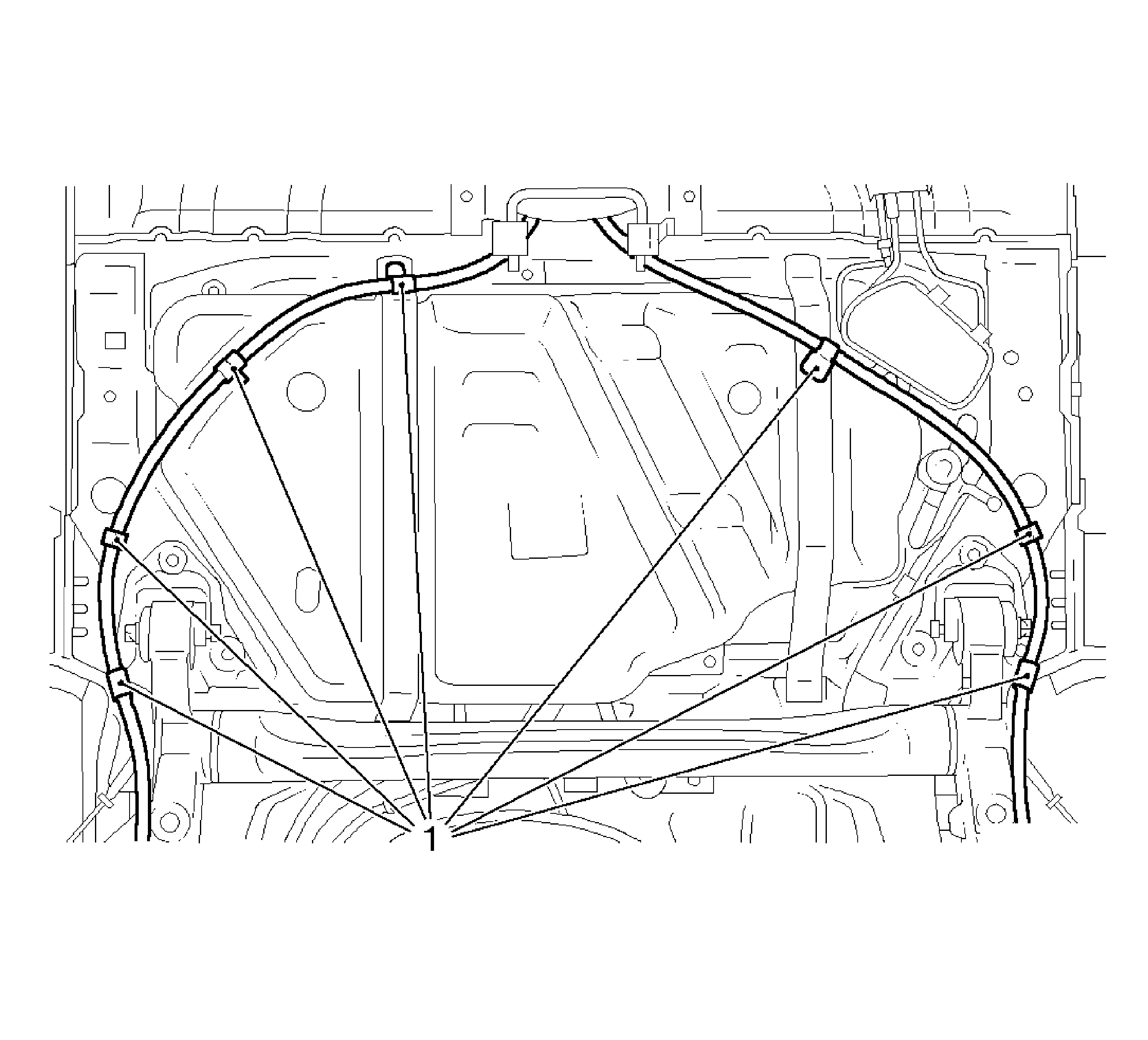
- Remove the parking brake cable from the bracket (1) in 7 places.
- Retract the jack.
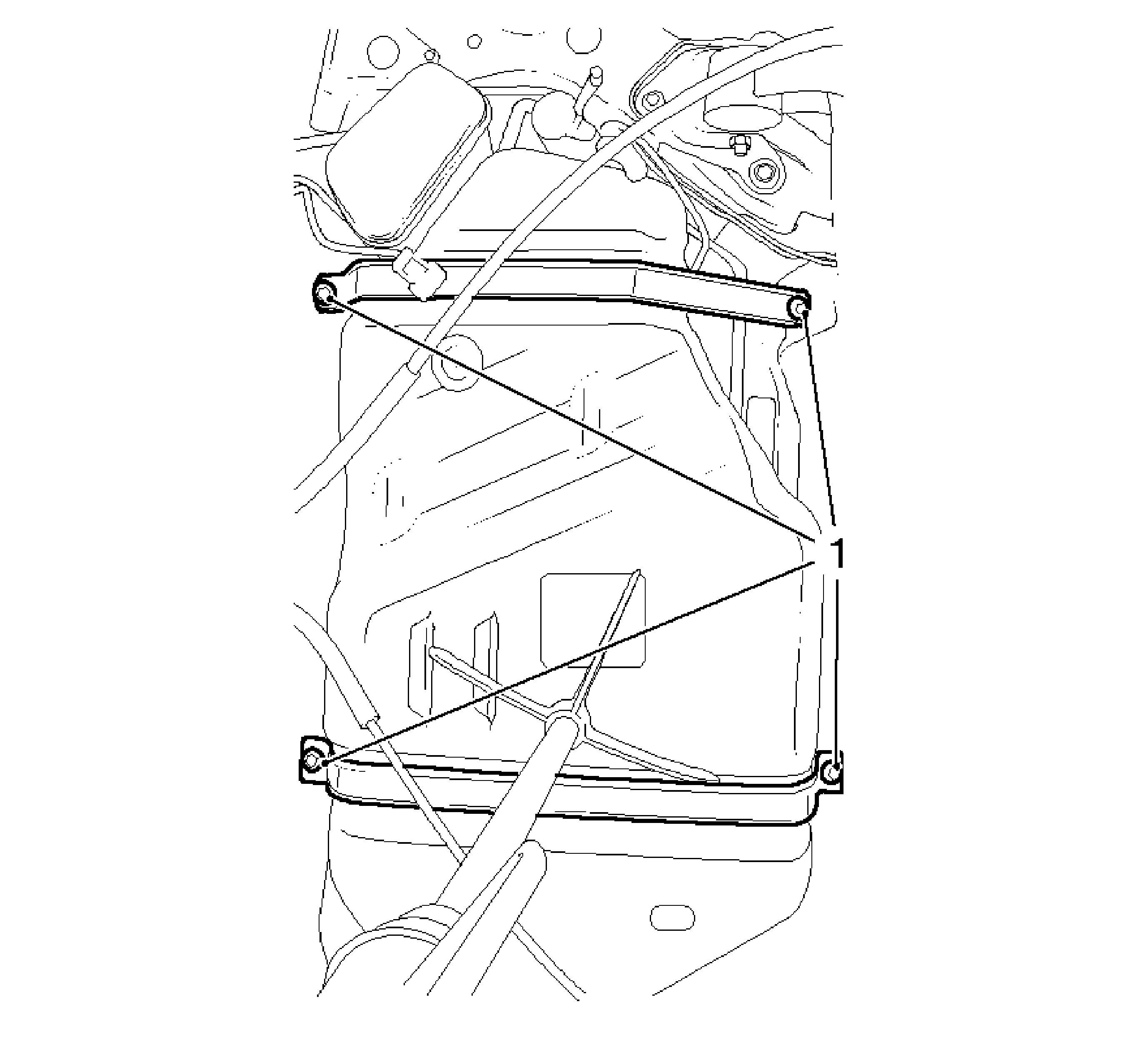
- Remove the 2 fuel tank holding straps.
Remove the 4 bolts (1).
Note: The wiring harness must be passed over the rear axel.
- With the aid of an assistant, remove fuel tank.
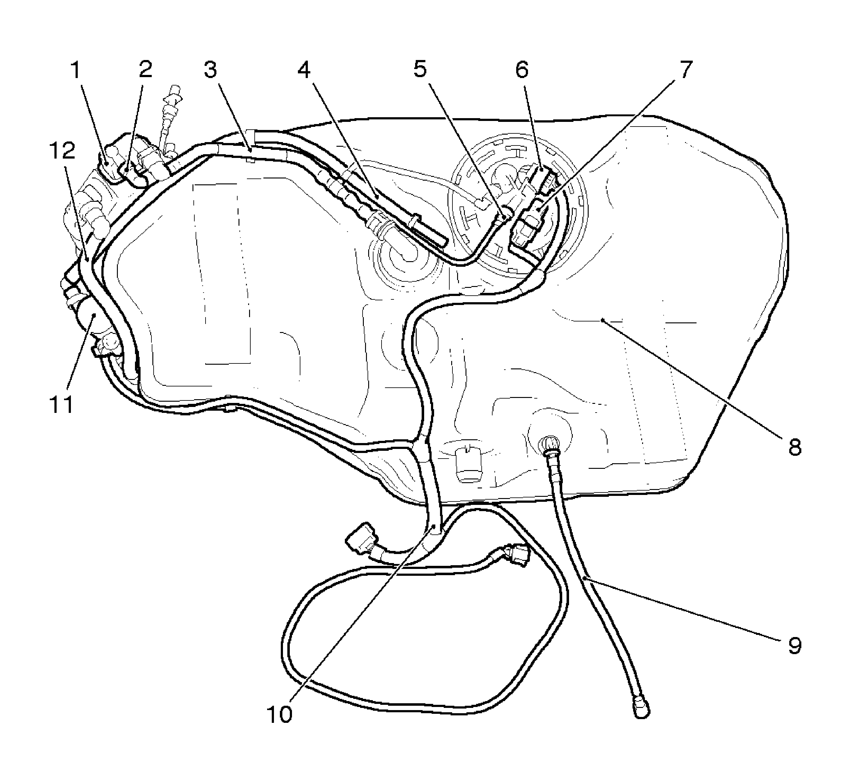
- fuel tank attaching parts:
| • | Evaporative emission canister (1) |
| • | Vent line from fuel tank to carbon canister (3) |
| • | Vent line from rear purge valve (4) |
| • | Rear fuel supply line (5) |
| • | Fuel tank fuel pump module (6) |
| • | Pressure sensor fuel tank (7) |
| • | Vent line to fuel filler pipe (9) |
| • | Vent line from evaporative emission canister to rear purge valve (12) |
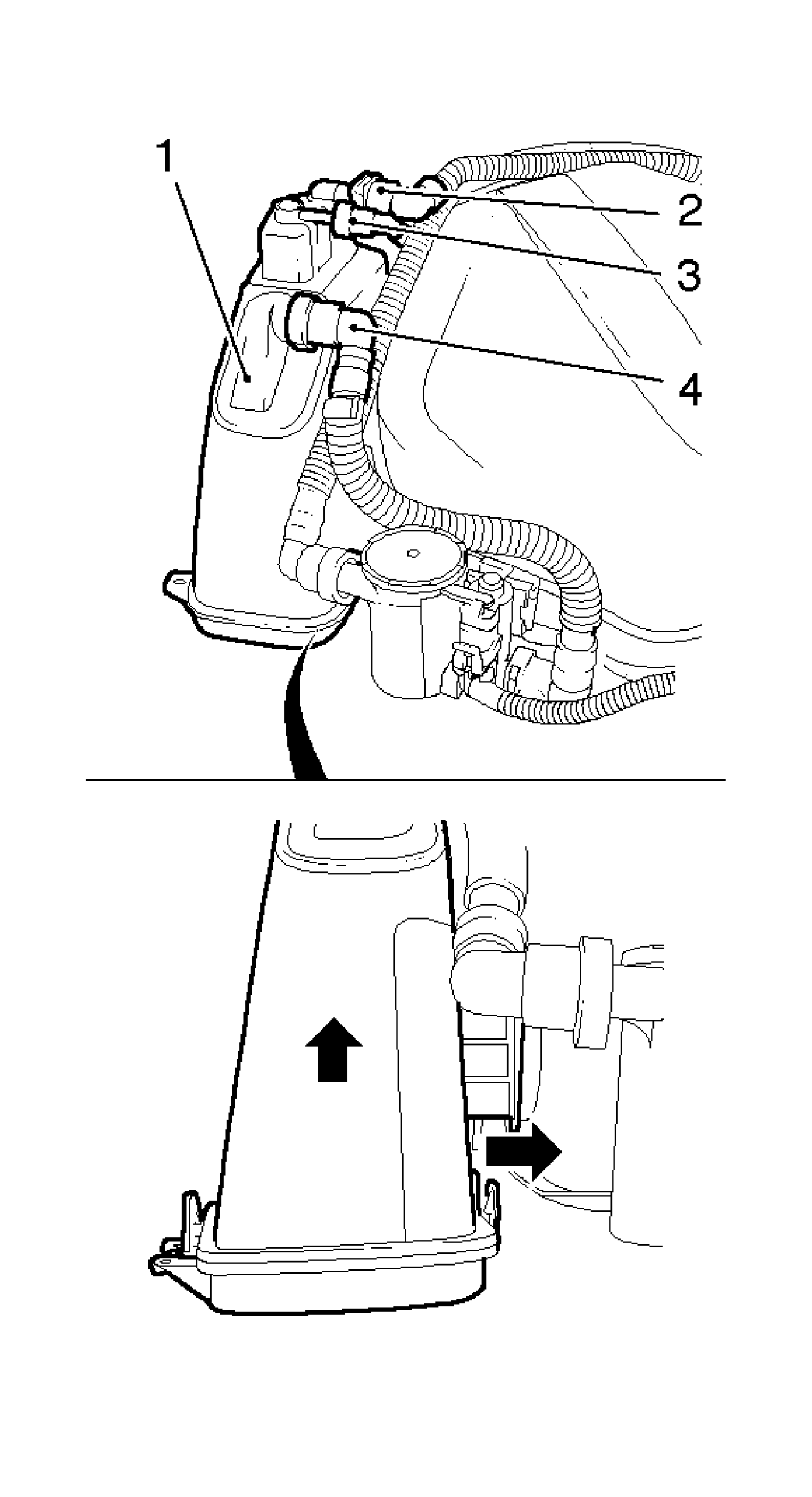
- Remove the evaporative emission canister (1).
| • | Remove the vent line from the fuel tank to the evaporative emission canister (2). |
| | Disconnect the quick-release fitting. |
| • | Remove the vent line from the evaporative emission canister to the rear purge valve (4). |
| | Disconnect the quick-release fitting. |
| • | Remove the rear vent line (3). |
| | Disconnect the quick-release fitting. |
| • | Release the bracket and remove the evaporative emission canister (arrows). |
- Remove the rear vent line from the bracket.
- Remove the rear purge valve (1).
| • | Remove the vent line from the evaporative emission canister to the rear purge valve (2). |
| | Disconnect the quick-release fitting. |
| • | Remove the vent line from the rear purge valve. |
| | Disconnect the quick-release fitting. |
| • | Remove the wiring harness from the rear purge valve (3). |
| | Remove the wiring harness plug. |
| • | Release the bracket and remove the rear purge valve (arrows). |
- Remove the 2 vent lines (2, 4) from the bracket.
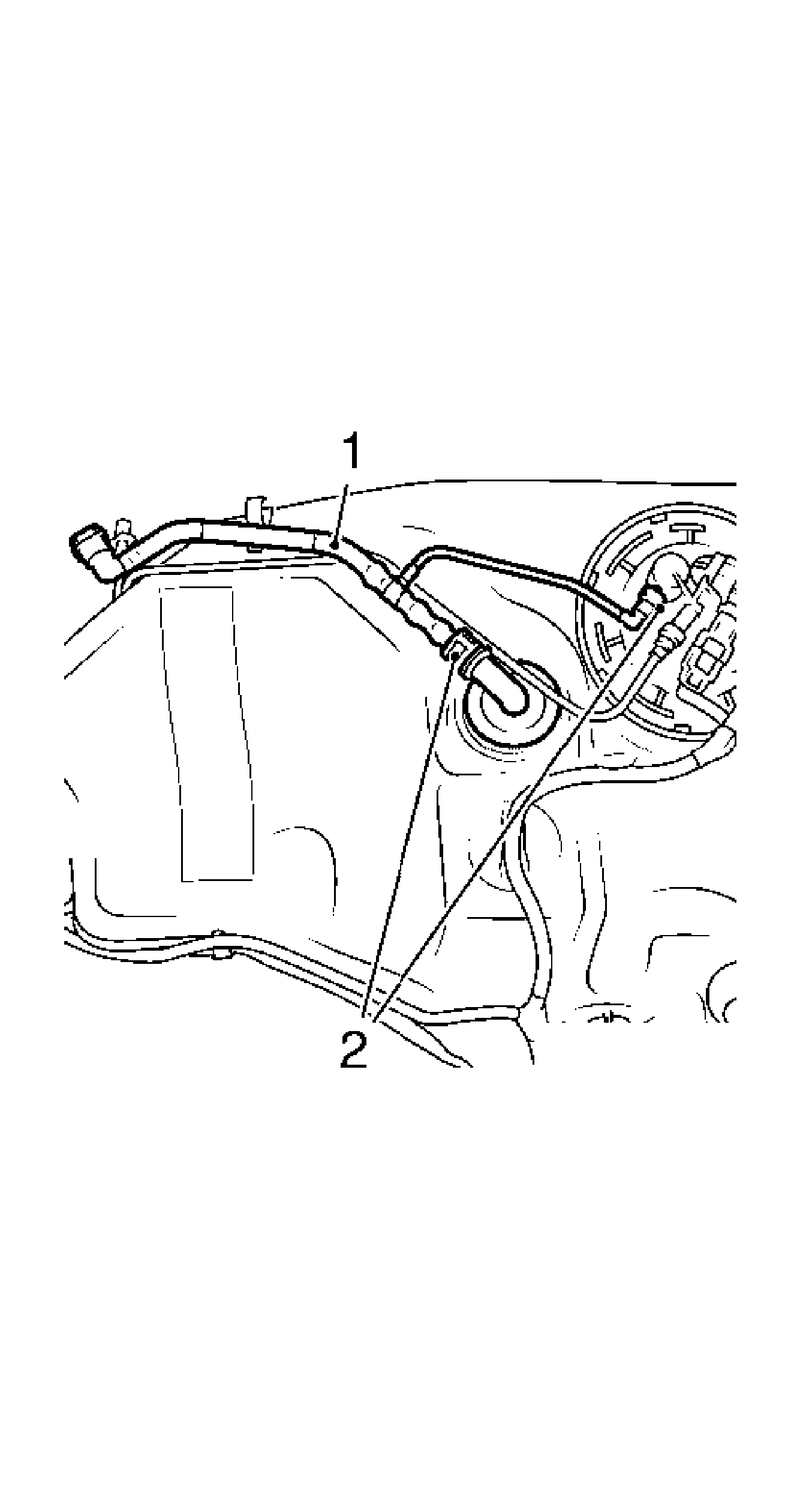
- Remove the vent line from the fuel tank to evaporative emission canister (1).
Disconnect the quick-release fittings (2).
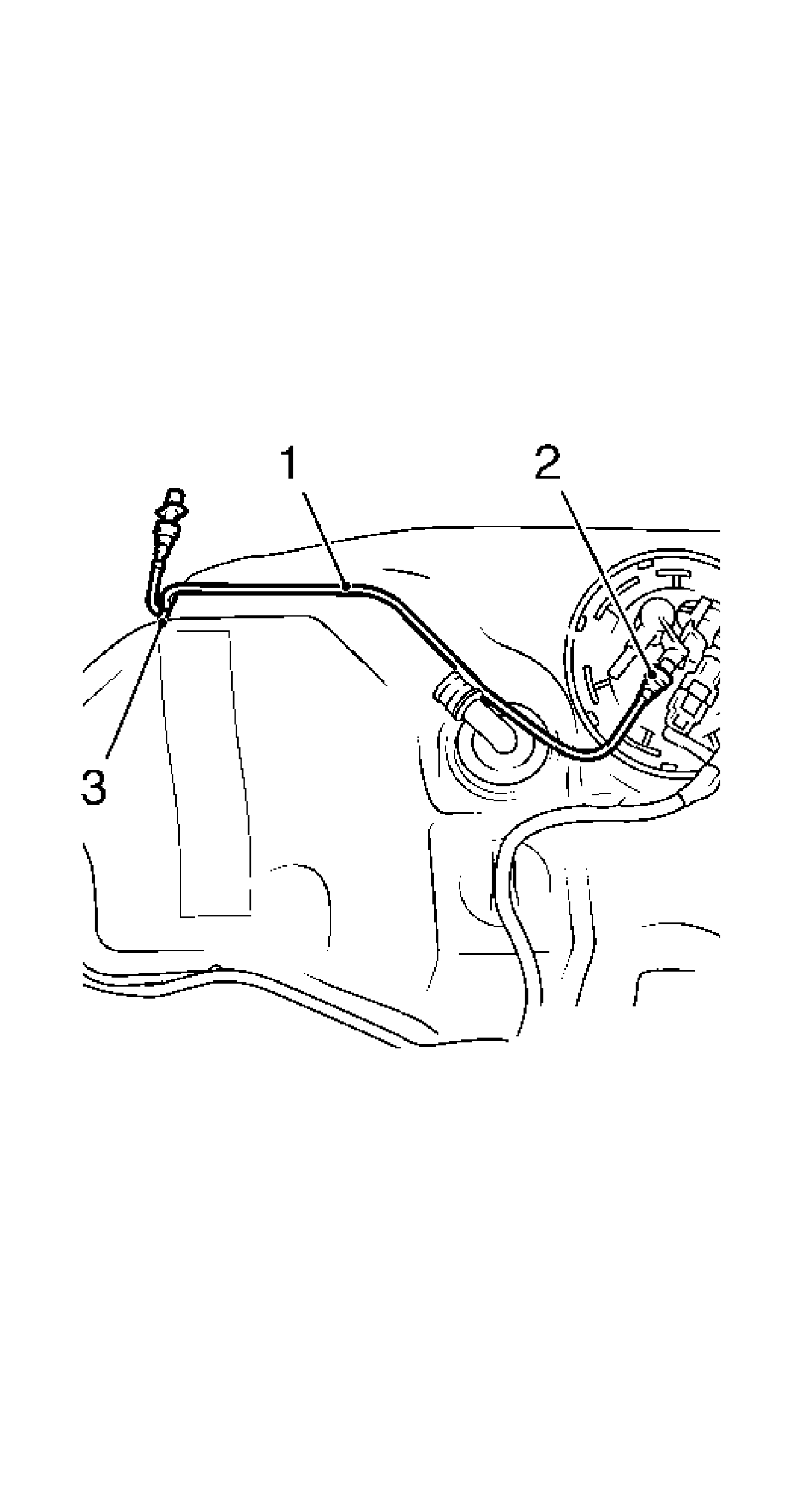
- Remove the rear fuel supply line (1).
| • | Disconnect the quick-release fittings (2). |
| • | Remove the rear fuel supply line from the bracket (3). |
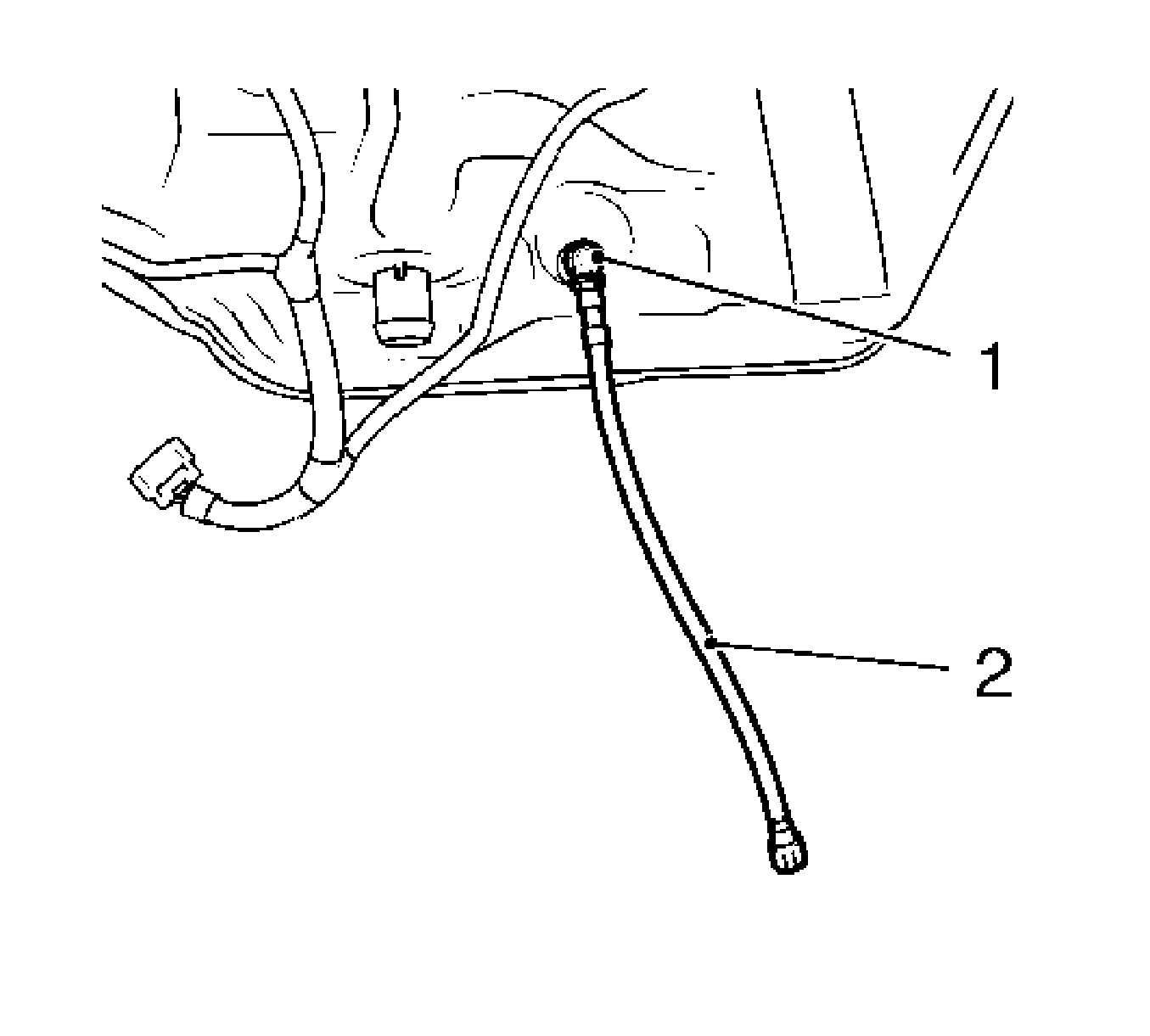
- Remove the vent line to the fuel filler pipe (2).
Disconnect the quick-release fitting (1).
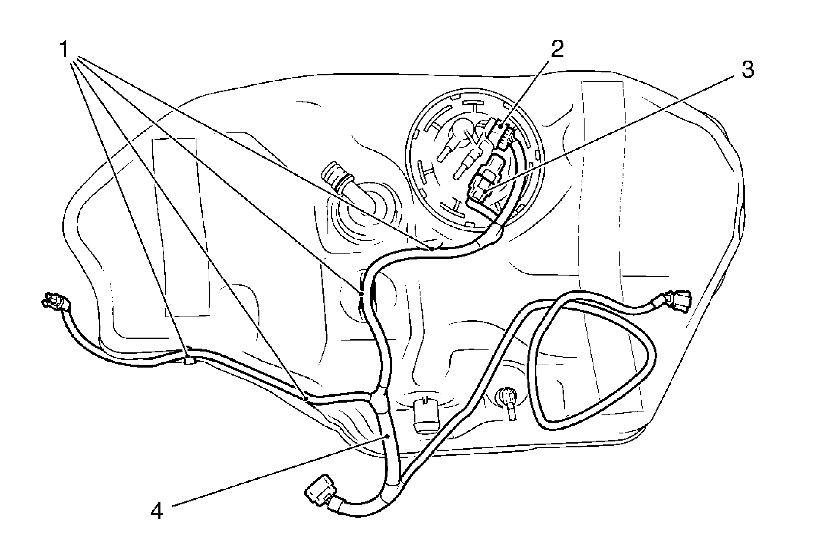
- Remove the wiring harness of the fuel tank fuel pump module (4).
| • | Remove the wiring harness plug of the fuel tank fuel pump module (2). |
| • | Remove the wiring harness plug of the pressure sensor fuel tank (3). |
| • | Remove the wiring harness from the bracket in 4 places (1). |
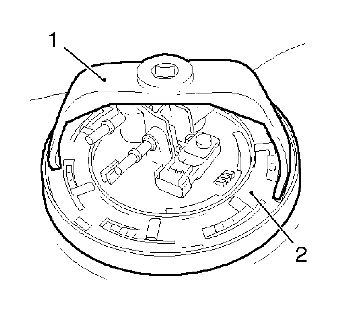
- Remove the fuel tank fuel pump module cover using
J 45722 /KM-J-45722.
| • | Rotate the retaining ring (1) counterclockwise. |
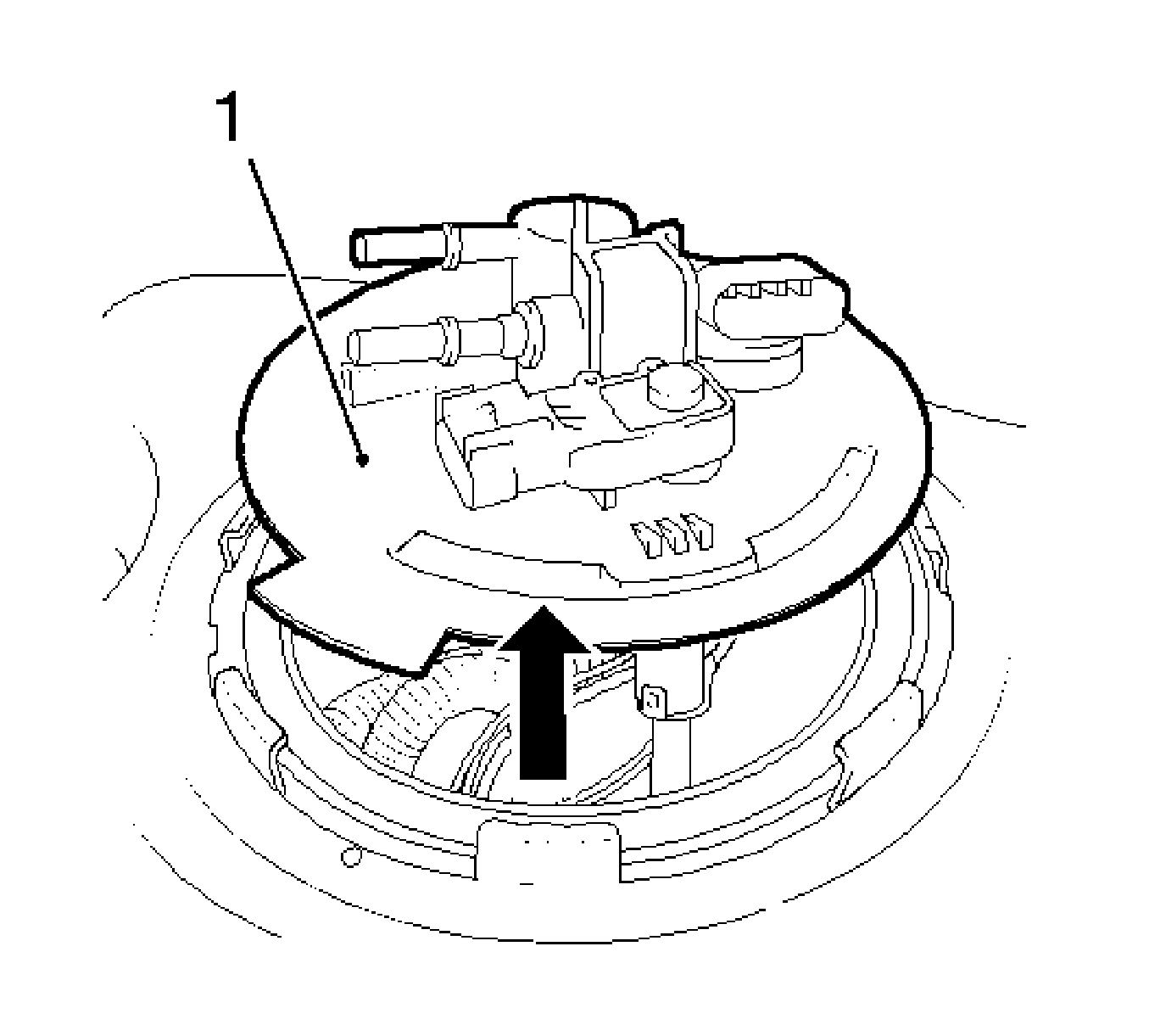
Warning: Drain the fuel from the fuel sender assembly into an approved container in order to reduce the risk of fire and personal injury. Never store the fuel in an open container
Note: Remove the fuel tank fuel pump module carefully upward.
- Remove the fuel tank fuel pump module from the fuel tank.
Remove the gasket.
- Remove the heat shield.
Remove the 3 nuts.
Installation Procedure
Caution: Refer to Fastener Caution in the Preface section.
- Install the heat shield.
Tighten
Tighten the 3 heat shield nuts to 8 N·m (71 lb in).
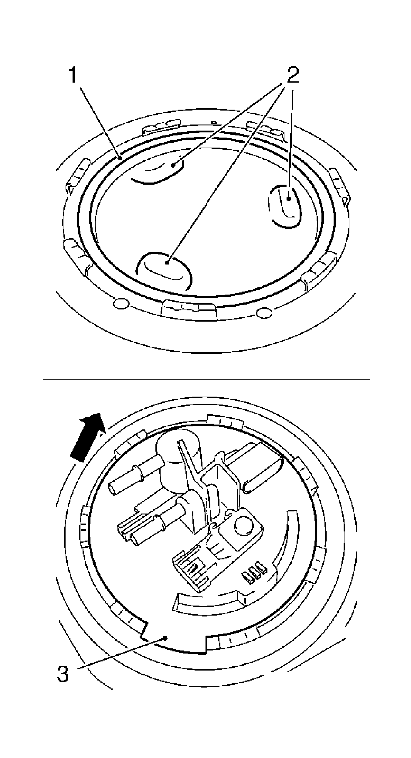
Warning: Drain the fuel from the fuel sender assembly into an approved container in order to reduce the risk of fire and personal injury. Never store the fuel in an open container
Note: Install the fuel tank fuel pump module carefully downward.
- Install the fuel tank fuel pump module in the fuel tank.
| | Note: The anti-twist protection (3) must point against the driving direction (arrow).
|
| • | Install the new gasket (1). |
| • | Install the fuel tank fuel pump module in the right position (2). |
- Install the fuel tank fuel pump module cover using
J 45722 /KM-J-45722.
Rotate the retaining ring clockwise.
- Install the wiring harness at the fuel tank fuel pump module.
| • | Connect the wiring harness plug at the fuel tank fuel pump module. |
| • | Connect the wiring harness plug to the pressure sensor fuel tank. |
| • | Install the wiring harness at the bracket in 4 places. |
- Install the vent line to the fuel filler pipe.
Connect the quick-release fitting.
- Install the rear fuel supply line.
| • | Connect the quick-release fittings. |
| • | Install the rear fuel supply line at the bracket. |
- Install the vent line at the fuel tank to the evaporative emission canister.
Connect the quick-release fittings.
- Install the 2 vent lines at the bracket.
- Install the rear purge valve.
| • | Install the rear purge valve at the bracket. |
| • | Connect the wiring harness at the rear purge valve. |
| | Connect the wiring harness plug. |
| • | Install the vent line at rear purge valve. |
| | Connect the quick-release fitting. |
| • | Install the vent line at the evaporative emission canister to the rear purge valve. |
| | Connect the quick-release fitting. |
- Install the rear vent line at the bracket.
- Install the evaporative emission canister.
| • | Install the evaporative emission canister at the bracket. |
| • | Install the rear vent line. |
| | Connect the quick-release fitting. |
| • | Attach the vent line at the evaporative emission canister to the rear purge valve. |
| | Connect the quick-release fitting. |
| • | Attach the vent line at the fuel tank to the evaporative emission canister. |
| | Connect the quick-release fitting. |
- With the aid of an assistant, position fuel tank.
- Install the 2 fuel tank holding straps.
Tighten
Tighten the 4 bolts to 23 N·m (17 lb ft).
- Extend the jack.
- Install the parking brake cable to the bracket in 7 places.
- Install the rear fuel lines to the middle fuel lines.
Connect the 2 quick-release fittings.
- Install the fuel filler tube to the fuel tank.
Tighten
Tighten the clamp to 3.5 N·m (31 lb in).
- Connect the vent hose to the vent pipe.
Connect the quick-release fitting.
- Install the wiring harness plug of the fuel tank fuel pump module.
- Install the complete exhaust system. Refer to
Exhaust System Replacement.
- Install the wiring harness of the pressure sensor (atmospheric pressure) to the fuel filler tube.
Install the 3 cable ties.
- Lower the vehicle halfway.
- Install the wiring harness of the pressure sensor (atmospheric pressure).
| • | Install the wiring harness plug. |
| • | Install the 3 cable ties. |
- Install the wheel housing inner paneling, right rear.
Tighten
| • | Tighten the 2 wheel housing inner paneling nuts to 2.5 N·m (22 lb in). |
| • | Tighten the 2 wheel housing inner paneling bolts to 2.5 N·m (22 lb in). |
- Mount the right rear wheel.
- Lower the vehicle halfway.
- Install the right rear wheel.
Tighten
Tighten the right rear wheel to 110 N·m (81 lb ft).
- Install the battery.
Connect the ground clamp to the ground terminal.
Tighten
Tighten the ground clamp nut to 5 N·m (44 lb in).
- For programming procedures, refer to
Control Module References.
- Close the hood.


