Special Tools
Removal Procedure
- Open the hood.
Warning: Refer to Battery Disconnect Warning in the Preface section.
- Disconnect the battery.
| • | Remove the ground connection from the negative terminal. |

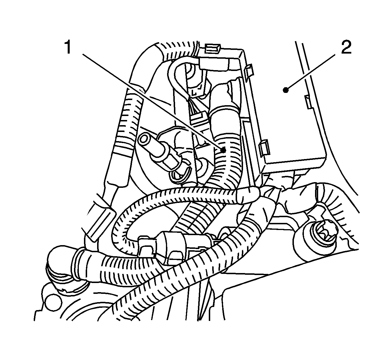
- Remove the engine venting pipe (1).
| • | Remove the wiring (2) from the cylinder head cover. |
| • | Disconnect the 2 quick-release fittings. |
- Remove the engine management wiring harness.
| • | Disconnect the 9 wiring harness plugs. |
| - | Valve, intake camshaft adjustment |
| • | Remove the 2 wiring harness brackets. |
| • | Put the wiring harness to the side. |
- Place a drain pan underneath.
Warning: Refer to Gasoline/Gasoline Vapors Warning in the Preface section.
- Release the fuel pressure via the test connection (1) using
J 34730-1A /KM-J-34730-91.
Collect the exiting fuel in a suitable container.

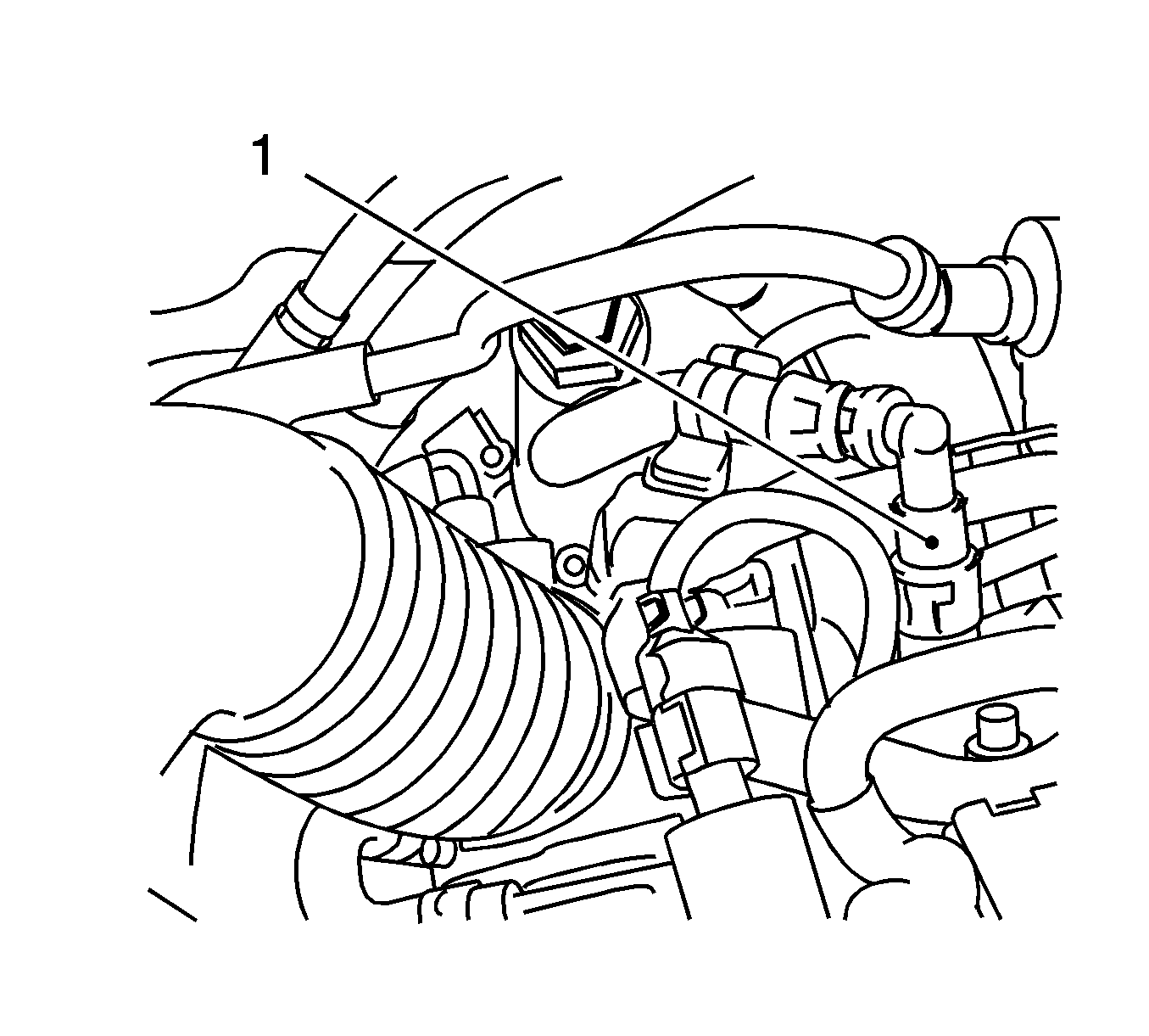
- Remove the fuel return line (1).
| • | Remove the quick-release fitting with
J 37088-A . |
| • | Seal the fuel line and the fuel rail with
KM-807 . |

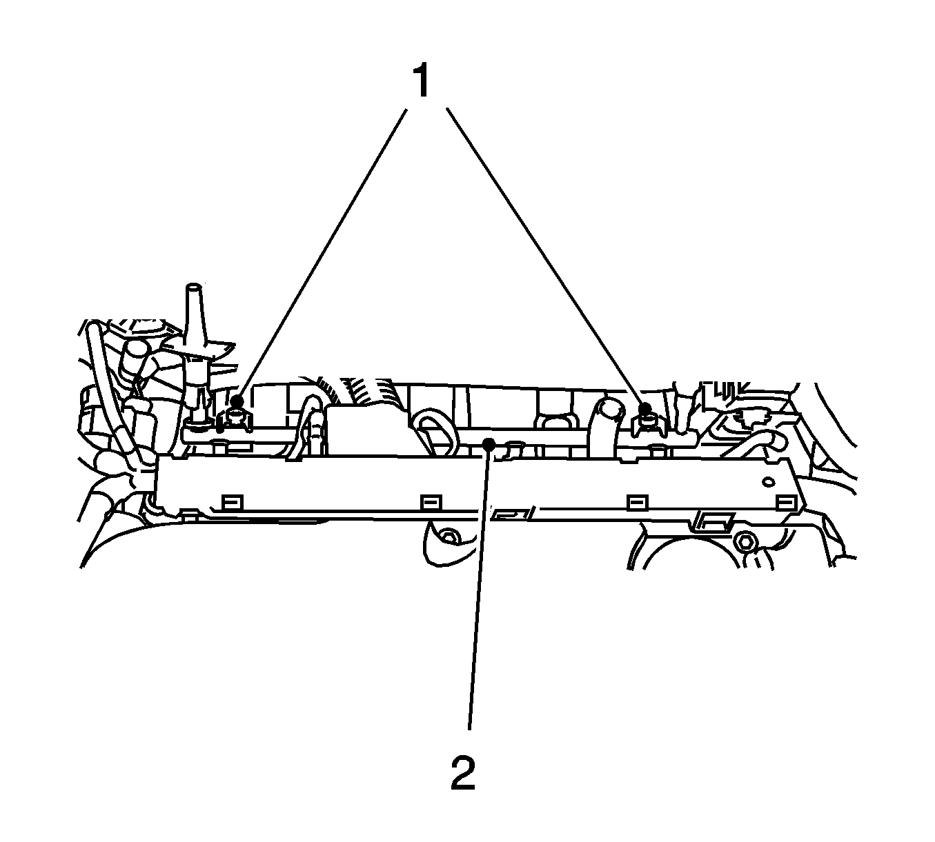
- Remove the fuel rail (2).
Remove the 2 bolts (1).

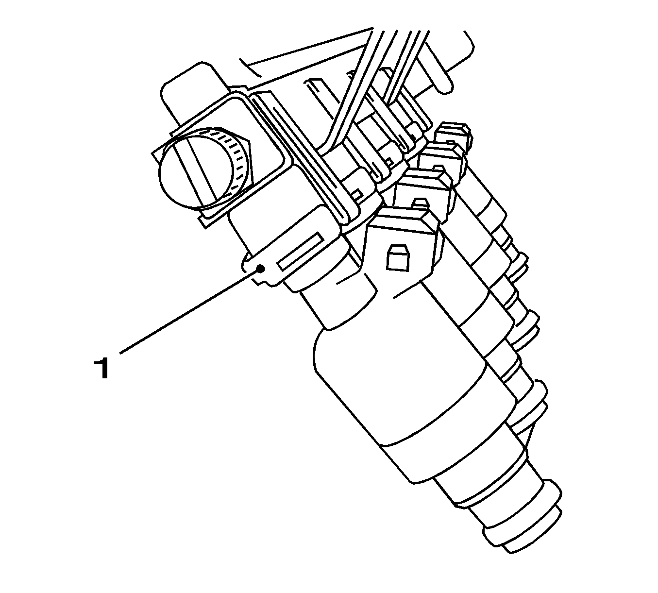
- Remove the injectors.
| • | Remove the 4 retaining clamps (1). |
| • | Pull out the 4 injectors. |
Installation Procedure
Note: Inspect the installation position and ensure correct fitting.
- Install the 4 injectors to the fuel rail.
| • | Install the 4 new seal rings. |
| • | Coat the seal ring with silicone grease (white). |
| • | Install the 4 injection valves. |
| • | Install the 4 retaining clamps. |
Caution: Refer to Fastener Caution in the Preface section.
- Install the fuel rail.
Tighten
Tighten the 2 bolts to 8 N·m (71 lb in).
- Install the fuel supply line to the fuel rail.
| • | Connect the quick release fitting. |
| • | Connect into the bracket. |
- Install the engine management wiring harness.
| • | Connect the 9 wiring harness plugs. |
| - | Intake camshaft actuator |
| • | Install the 2 wiring harness brackets. |
- Install the engine vent hose.
| • | Connect the 2 quick-release fittings. |
| • | Connect the wiring harness to the cylinder head. |
- Connect the battery.
Install the ground connection to the negative terminal.
Tighten
Tighten the ground connection nut to 5 N·m (44 lb in).
- For programming procedures, refer to
Control Module References.
- Close the hood.


