For 1990-2009 cars only
Special Tools
| • | MK-6340 Locking Tool |
| • | KM-6625 Flywheel Locking Device |
| • | MK-6628 Locking Tool |
Removal Procedure
- Remove the camshaft cover. Refer to Camshaft Cover Replacement.
- Remove the drive belt. Refer to Drive Belt Replacement.
- Insert MK-6628 (1) into the camshaft.
- Raise the vehicle by its full height.
- Remove KM-6625 .
- Set the engine to 60 degrees (measurement l) before TDC.
- Lower the vehicle by its full height.
- Remove the toothed belt tensioner (1).
- Place a drip pan underneath.
- Remove MK-6340 .
- Remove the closure bolt (2) of the intake camshaft adjuster (1) or the closure bolt (4) of the exhaust camshaft adjuster (3).
- Detach the intake camshaft adjuster (1) or the exhaust camshaft adjuster (3).
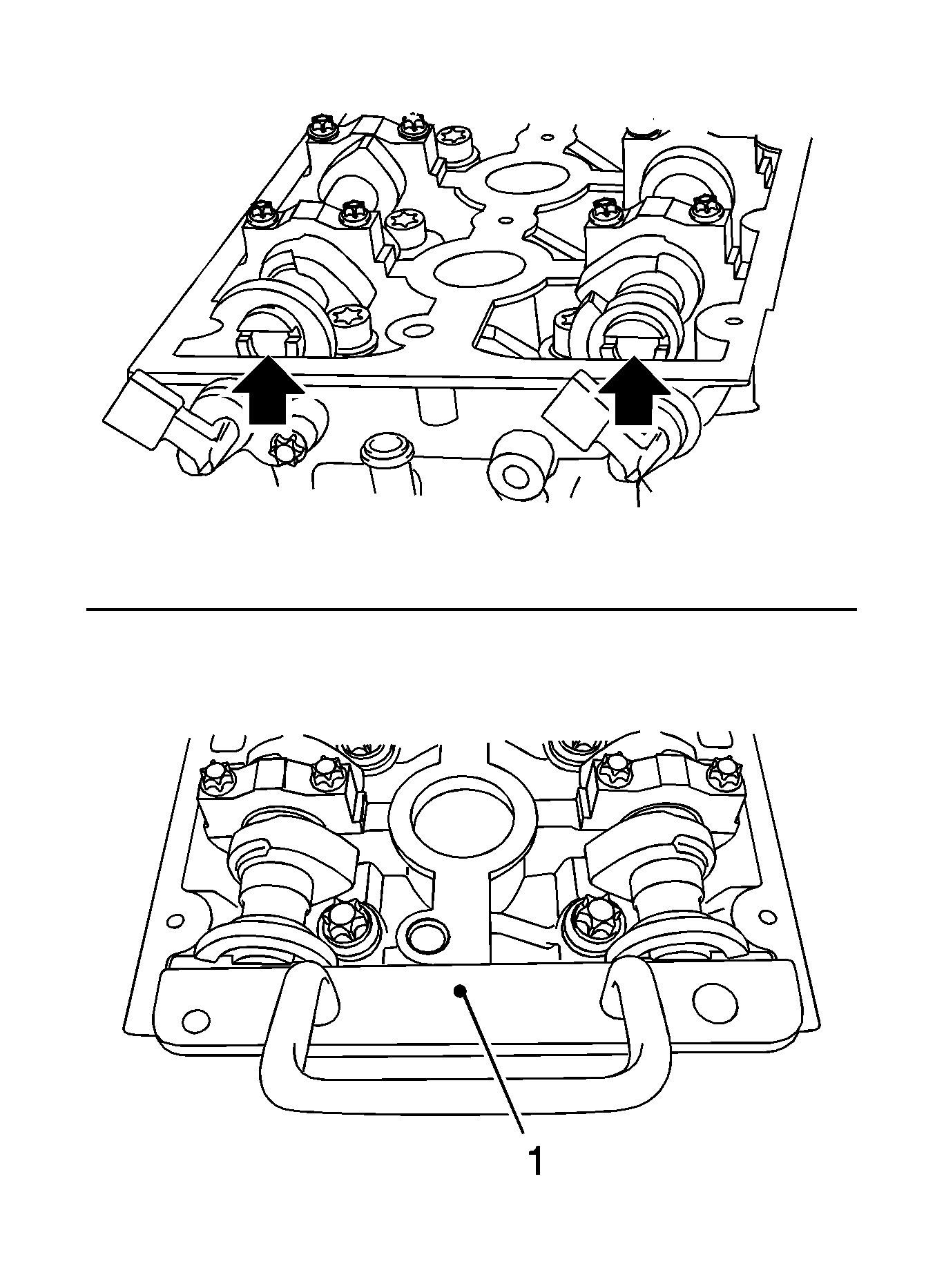
Turn the camshaft by the hexagon until the groove on the end of the camshafts is horizontal (arrows).
Detach the screwed connection.
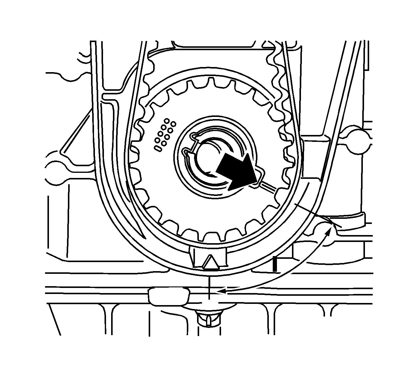
Set the crankshaft in the direction of engine rotation to 60 degrees (measurement l) before TDC.
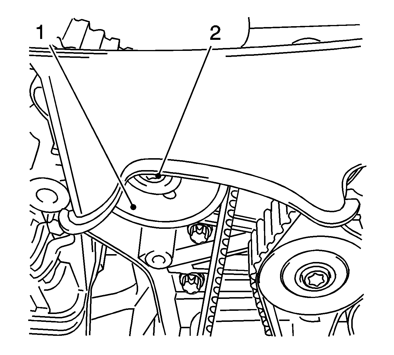
Remove the bolt (2).
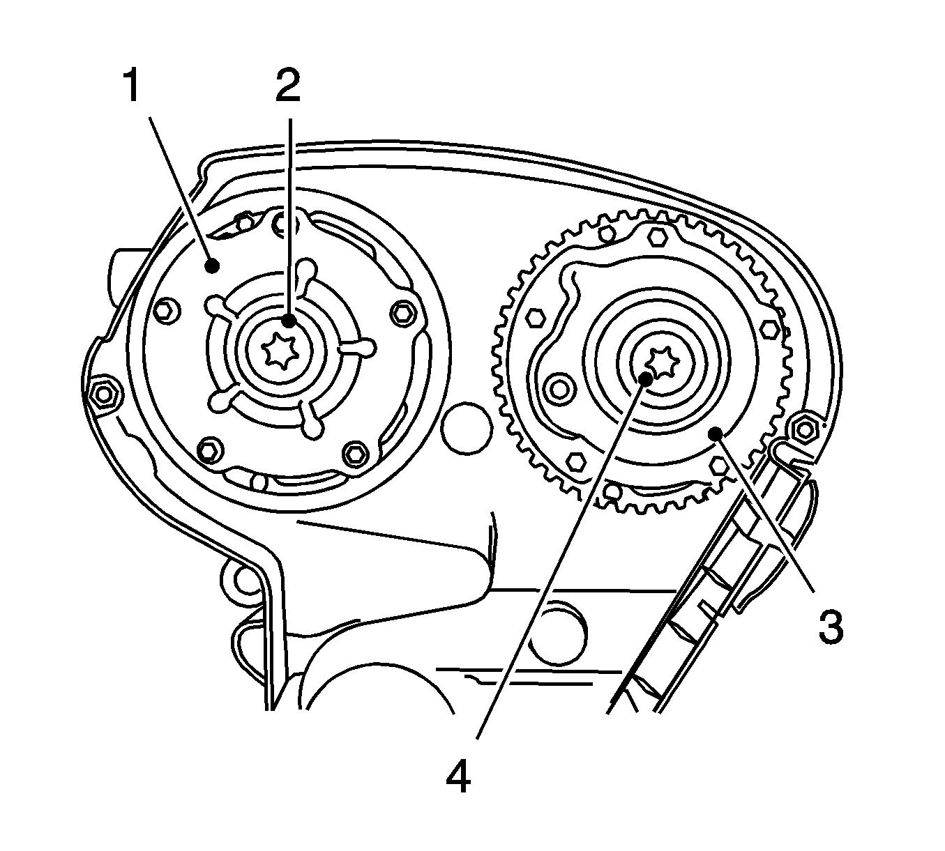
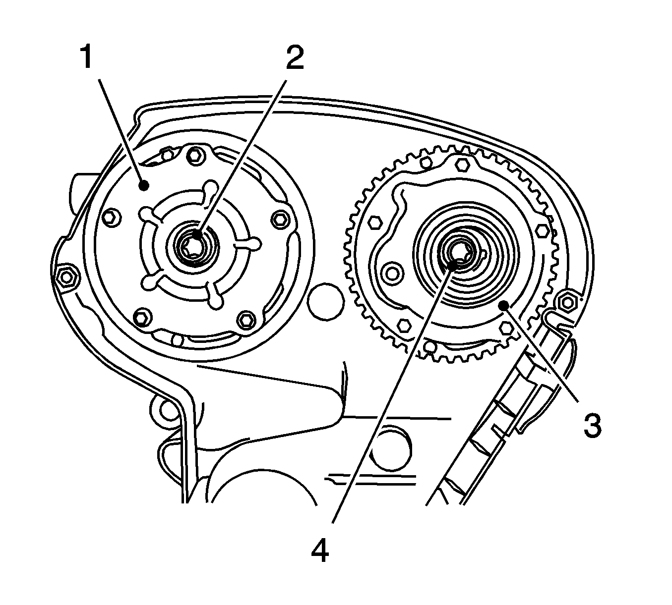
| • | Counterhold against the hexagon of the corresponding camshaft with an open-ended wrench. |
| • | Remove the bolt (2, 4). |
Installation Procedure
- Attach the intake camshaft adjuster or the exhaust camshaft adjuster.
- Install the bolt.
- Insert MK-6340 in the camshaft adjuster.
- Fasten the intake camshaft adjuster or the exhaust camshaft adjuster.
- Counterhold at the camshaft hexagon.
- Tighten the closure bolt.
- Replace the seal ring.
- Clean the thread.
- Intake the toothed belt tensioner.
- Remove MK-6628 .
- Raise the vehicle by its full height.
- Set the crankshaft to cylinder number 1 ignition TDC.
- Block the crankshaft.
- Lower the vehicle by its full height.
- Install the drive belt. Refer to Drive Belt Replacement.
- Install the camshaft cover. Refer to Camshaft Cover Replacement.
Note: Do not tighten the bolt.
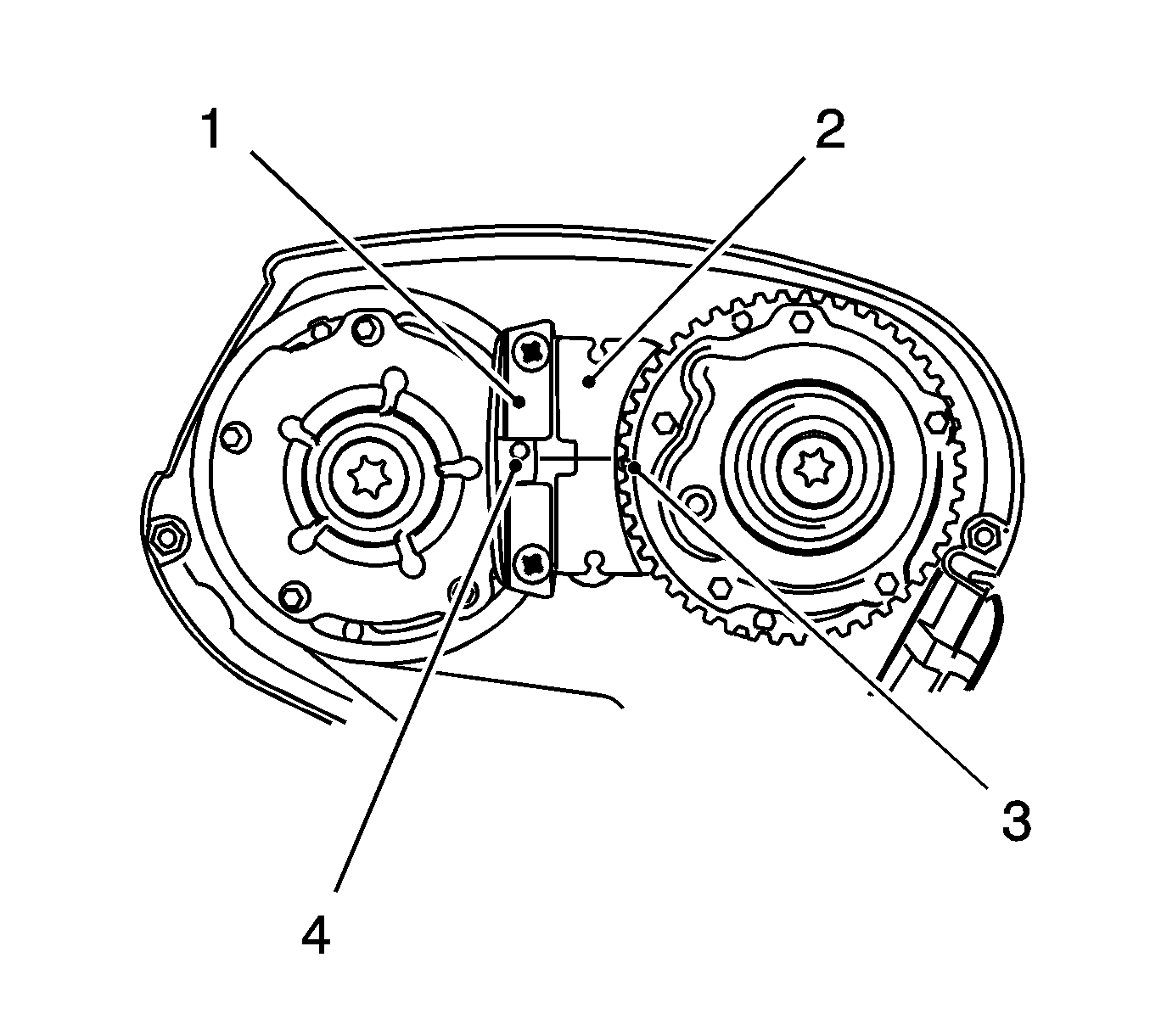
| • | Insert MK-6340 (1, 2) in the camshaft adjuster as shown. |
| Note: The spot-type marking (4) on the intake camshaft adjuster does not correspond to the groove of MK-6340 during this process but must be somewhat above as shown. |
| • | The spot type marking (3) on the exhaust camshaft adjuster must correspond to the groove on MK-6340 . |
Caution: Refer to Fastener Caution in the Preface section.
Tighten
Tighten the bolt to 65 N·m (48 lb ft) plus 120 degrees plus 15 degrees.
Tighten
Tighten the closure bolt to 30 N·m (22 lb ft).
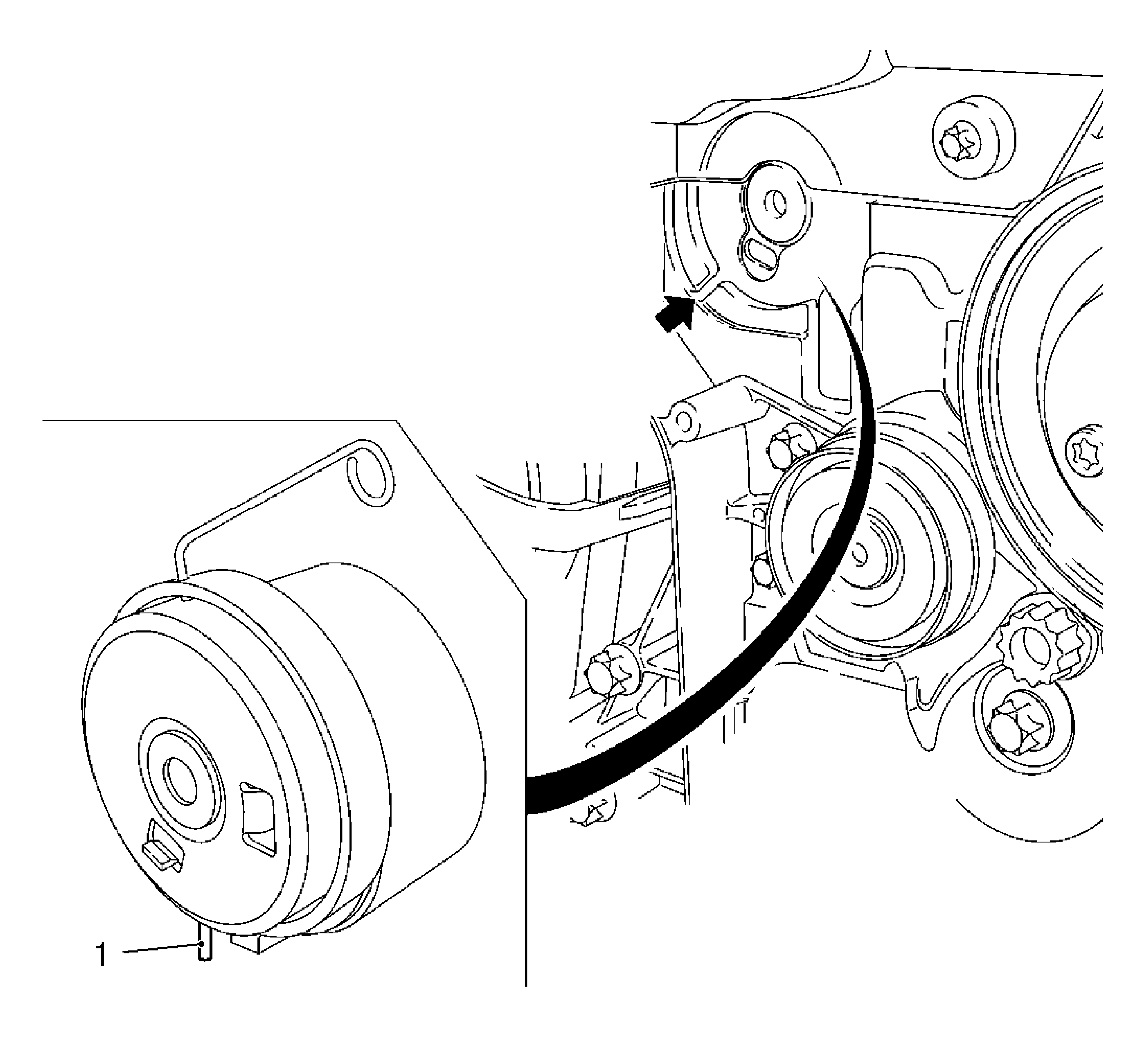
Insert the toothed belt tension roller.
| • | Use a new bolt. |
Tighten
Tighten the bolt to 20 N·m (15 lb ft).
| • | Released leg of spring (1) of the toothed belt tension roller must engage in the cut-out (arrow) of the pump module. |
Marking, toothed belt drive gear and oil pump housing adapter must align.
| • | Insert KM-6625 . |
| • | Install the bolted connection. |
