Antenna Cable Replacement Coupe
Special Tools
KM6067 Radio Removal Tools
Removal Procedure
Note: Replace or repair wiring harnesses observing the safety regulations of electrics/electronics.
Warning: Refer to Battery Disconnect Warning in the Preface section.
- Disconnect the battery.
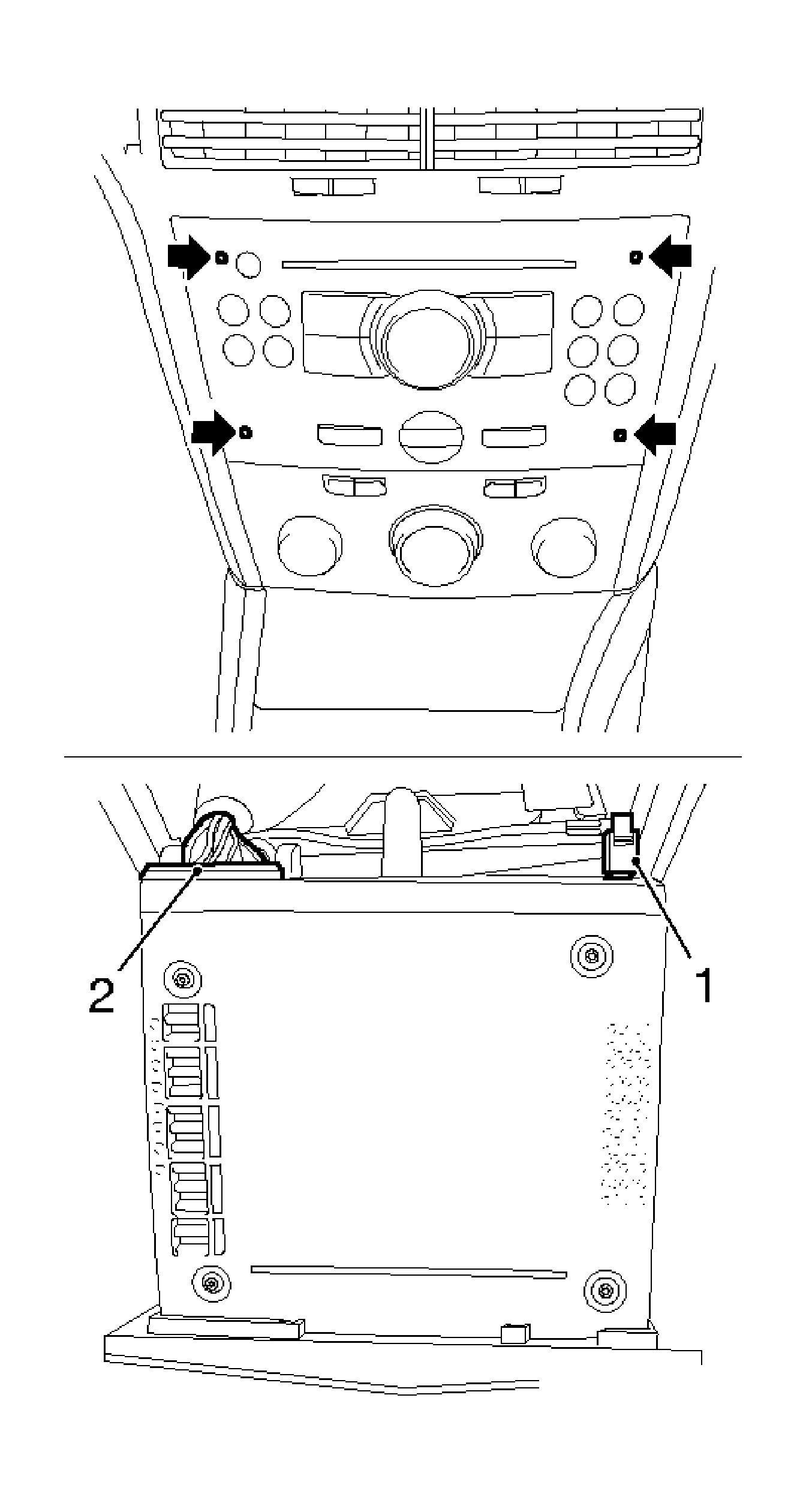
- Remove the radio.
| • | Install the removal bar
KM6067 into the openings (arrows) until it engages. |
| • | Pull both removal bars outwards and at the same time withdraw the radio from the holder. |
- Disconnect the wiring harness plug.
Disconnect the 2 wiring harness plugs (1, 2).
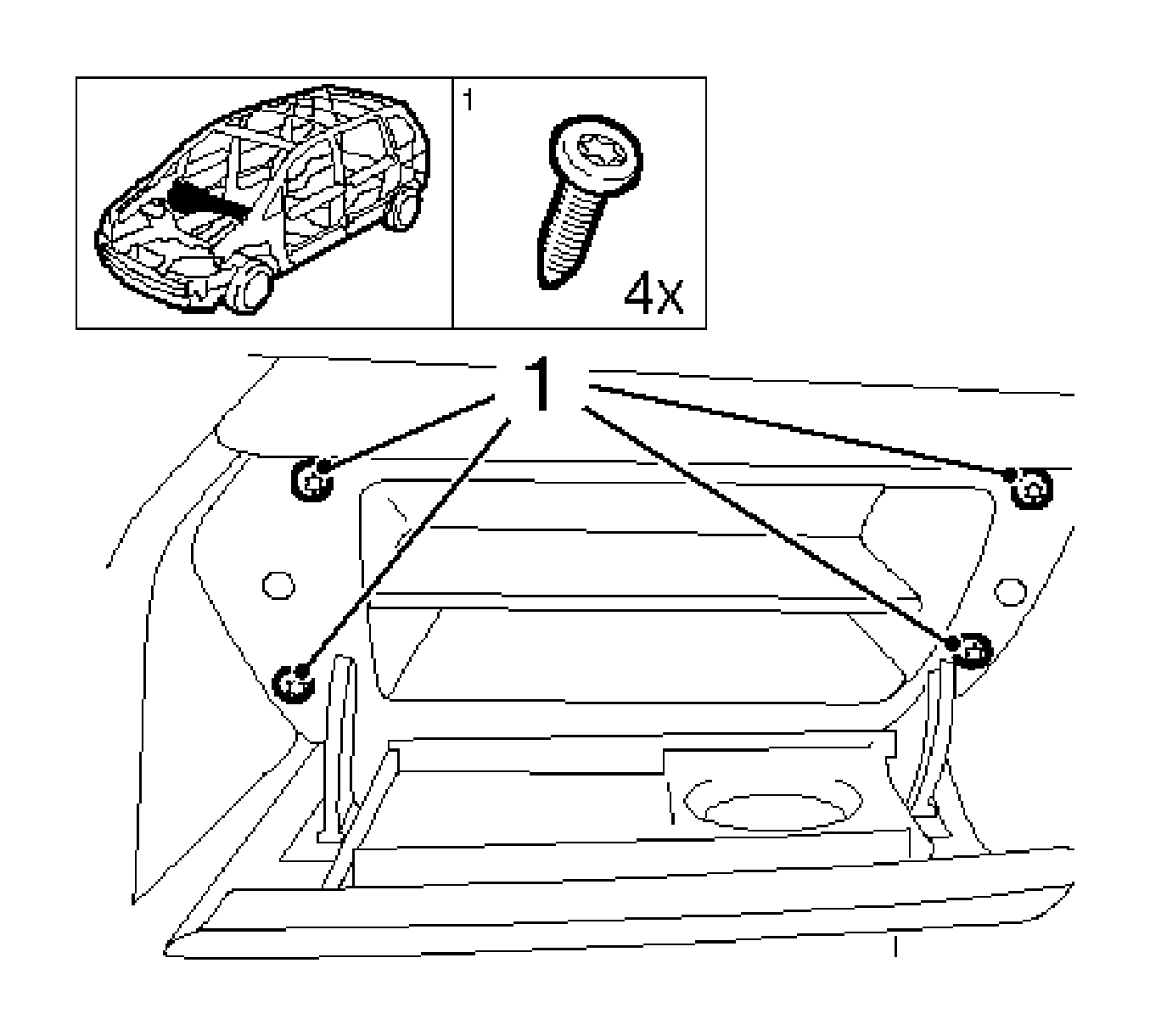
- Remove the instrument panel (I/P) compartment.
| • | Open the I/P compartment door. |
| • | Remove the 4 bolts (1). |
| • | Disconnect the wiring harness plug. |
| • | Remove the I/P compartment. |
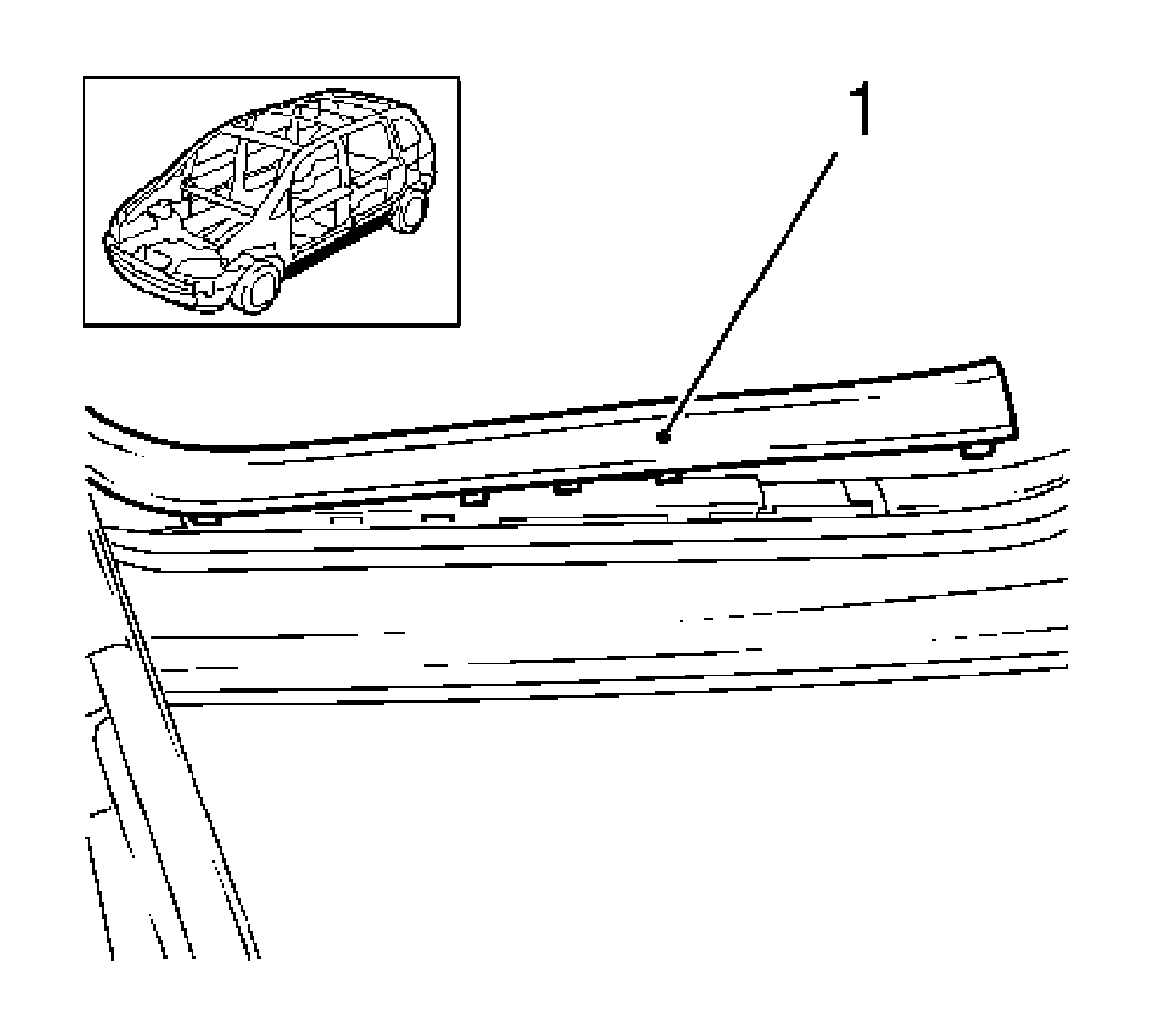
- Remove the door sill inner panel.
| • | Remove the sill inner panel (1). |
- Lower the headlining trim panel. Refer to
Headlining Trim Panel Replacement.
- Remove the rear compartment side trim panel. Refer to
Rear Compartment Side Trim Panel Replacement.
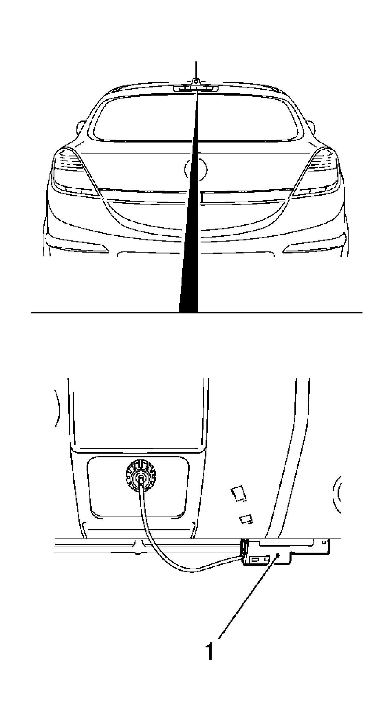
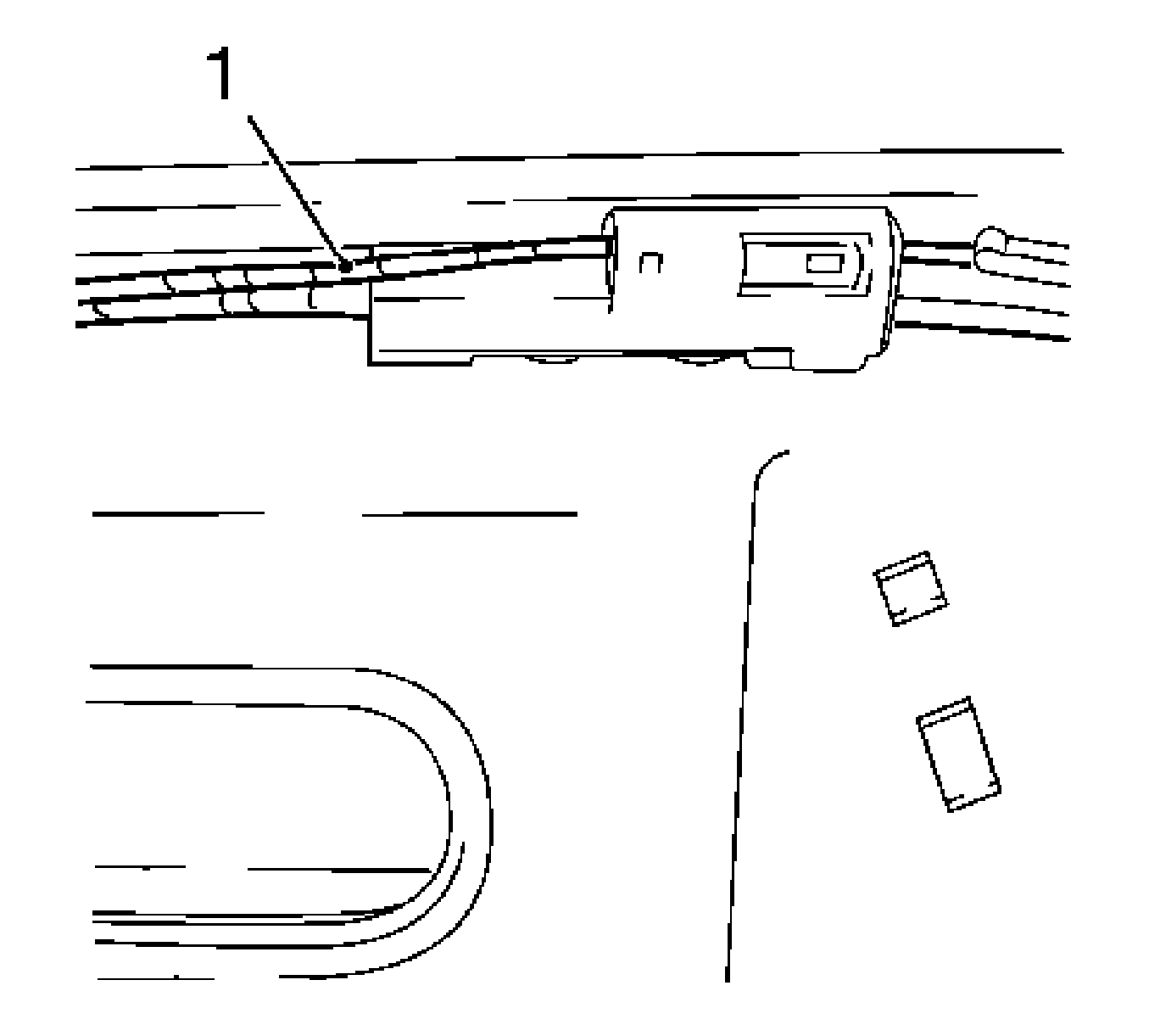
- Disconnect the roof antenna wiring harness plug (1).
- Disconnect the antenna cable (1) and insulate the remaining ends.
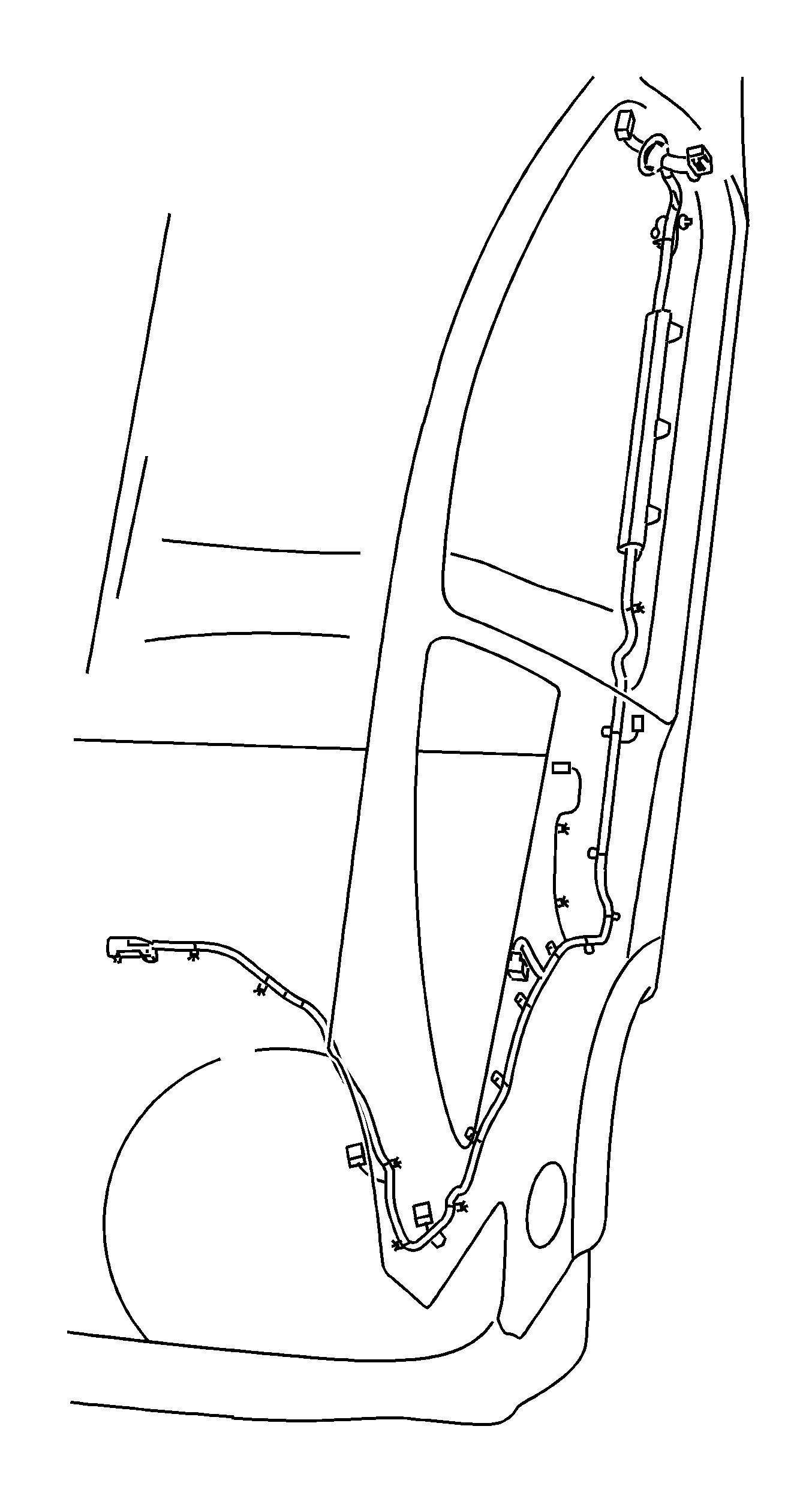
Note:
| • | The old antenna cable remains in the wiring harness. |
| • | The new antenna cable is routed parallel to the existing antenna cable and is secured with duct tape and cable ties. |
- Route the antenna cable up to behind the I/P compartment.
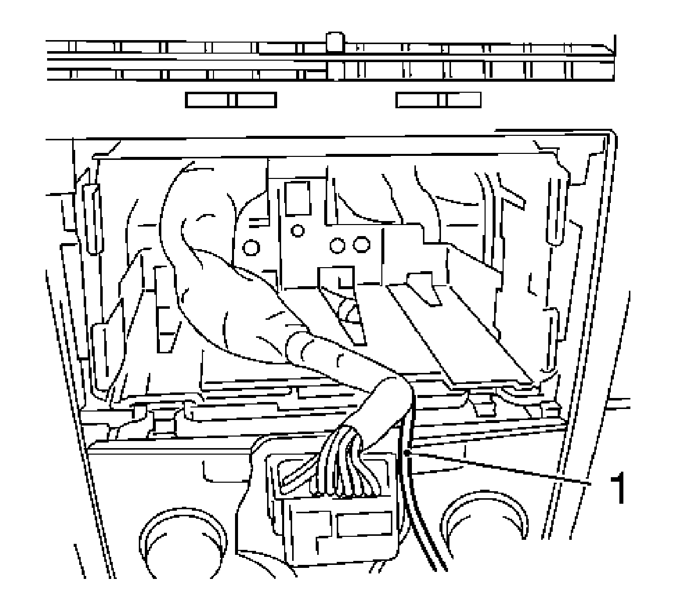
- Disconnect the antenna cable from I/P padding wiring harness.
Disconnect and insulate the wiring harness (1).
Installation Procedure
- Connect the wiring harness plug of the roof aerial.
- Install headlining trim panel. Refer to
Headlining Trim Panel Replacement.
- Remove the rear compartment side trim panel. Refer to
Rear Compartment Side Trim Panel Replacement.
- Install the radio.
| • | Connect the 2 wiring harness plugs. |
| • | Push the radio into the holder until it engages. |
- Install the I/P compartment.
Connect the wiring harness plug.
Caution: Refer to Fastener Caution in the Preface section.
- Install the I/P compartment.
Tighten
Tighten the 4 screws to 4 N·m (35 lb in).
- Close the I/P compartment door.
- Install the door sill inner panel.
Clip in the 5 clips.
- Connect the battery.
- For reprogramming procedures, refer to
Control Module References.
Antenna Cable Replacement Sedan
Special Tools
KM6067 Radio Removal Tools
Removal Procedure
Warning: Refer to Battery Disconnect Warning in the Preface section.
- Disconnect the battery.

- Remove the radio.
| • | Install the removal bar
KM6067 into the openings (arrows) until it engages. |
| • | Pull both removal bars outward and at the same time withdraw the radio from the holder. |
- Disconnect the wiring harness plug.
Disconnect the 2 wiring harness plugs (1, 2).

- Remove the instrument panel (I/P) compartment.
| • | Open the I/P compartment door. |
| • | Remove the 4 bolts (1). |
| • | Disconnect the wiring harness plug. |
| • | Remove the I/P compartment. |

- Remove the door sill inner panel.
| • | Remove the door sill inner panel. |
- Lower the headlining. Refer to
Headlining Trim Panel Replacement.
- Remove the rear compartment side trim panel. Refer to
Rear Compartment Side Trim Panel Replacement.

- Disconnect the roof antenna wiring harness plug (1).

- Disconnect the antenna cable (1) and insulate the remaining ends.
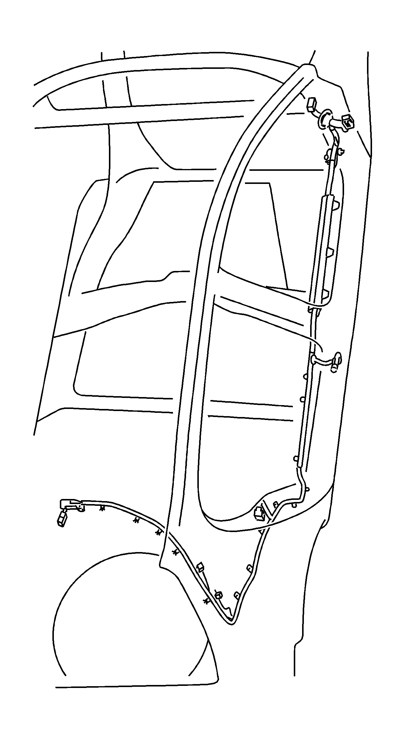
Note:
| • | The old antenna cable remains in the wiring harness. |
| • | The new antenna cable is routed parallel to the existing antenna cable and is secured with duct tape and cable ties. |
- Route the antenna cable up to behind the I/P compartment.

- Disconnect the antenna cable from the instrument panel padding wiring harness.
Disconnect and insulate the wiring harness (1).
Installation Procedure
- Connect the roof wiring harness.
- Install the headlining. Refer to
Headlining Trim Panel Replacement.
- Install the radio.
| • | Connect the 2 wiring harness plugs. |
| • | Radio must audibly engage. |
- Install the I/P compartment.
Connect the wiring harness plug.
Caution: Refer to Fastener Caution in the Preface section.
- Install the I/P compartment.
Tighten
Tighten the 4 screws to 4 N·m (35 lb in).
- Install the sill molding assembly.
Clip in the 5 clips.
- Connect the battery.
- For reprogramming procedures, refer to
Control Module References.


