Special Tools
| • | MK-6005-A
/KM-6005-3/KM-6005-1-A/KM-6005-4-A Remover/Installer |
| • | MKM-6615-10
Hydraulic Thrust Rod /MKM-6615-10/MKM-6615-11/MKM-6615-12/MKM-6615-13 |
Removal Procedure
Important: In general, both damping bushings must be replaced in the lower control arm.
- Remove the lower control arm. Refer to
Lower Control Arm Replacement
.

Important:
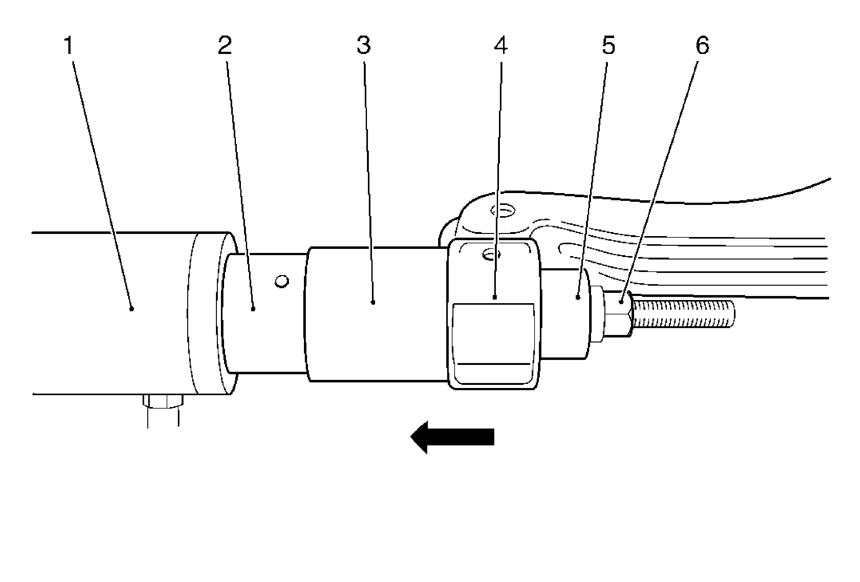
| • | Ensure the tool arrangement is attached correctly. |
| • | The arrow in the illustration shows the direction for pressing out. |
- Attach the
MKM-6615-10
-10 to the control arm.
| • | Guide the special tool assembly through the bore hole of the damping bushing (4). |
Important: Note any excessive rise in pressure in the pressure gage of
MKM-6616
. Check installation position of the special tool. Maximum loading of the hydraulic thrust rod
MKM-6615-10
(1) 70 kN or 260 bar.
- Press out the bushing.
- Remove the bushing from
MK-6005-A
.
Installation Procedure

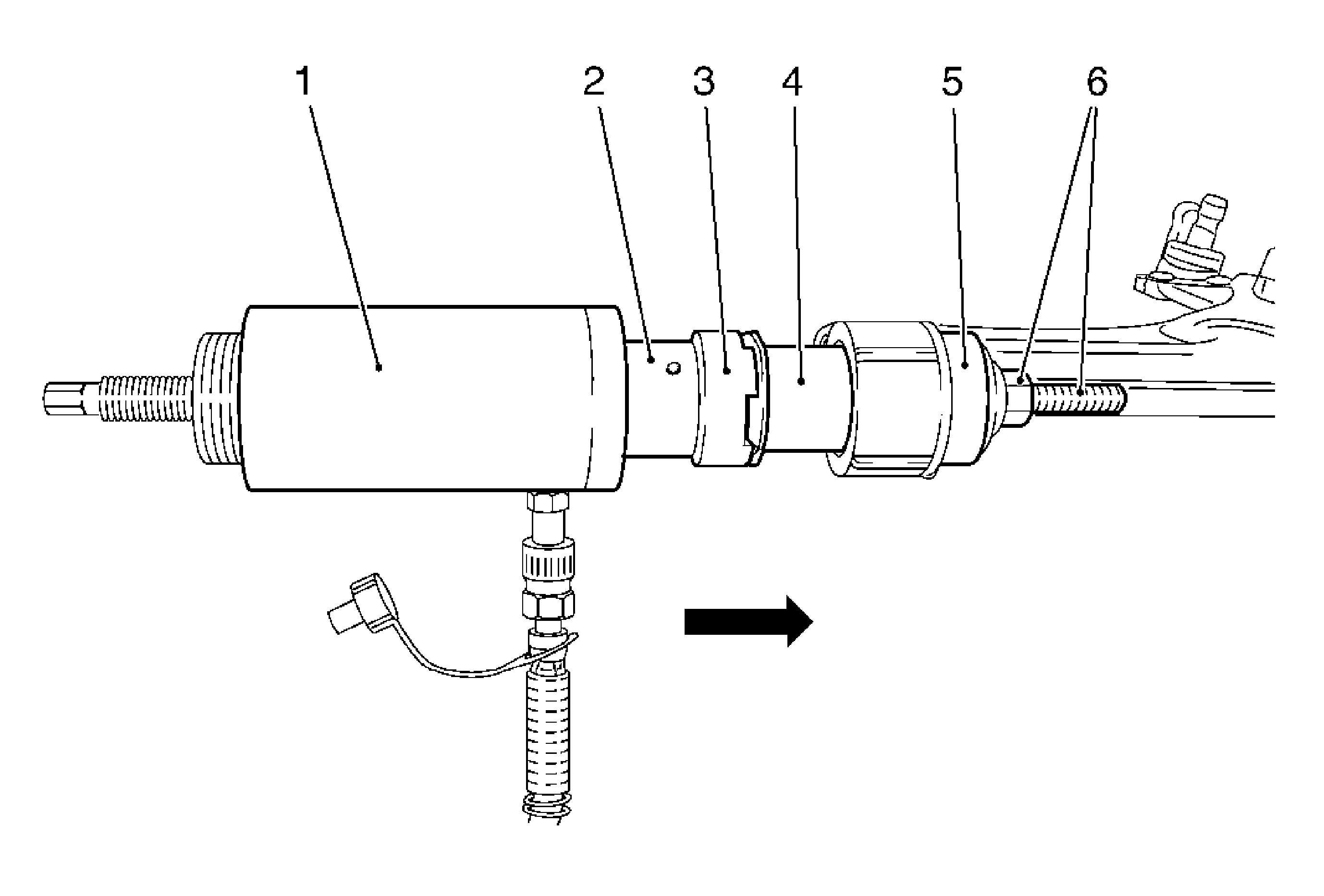
Important:
| • | Ensure the nut from
MKM-6615-10
-13 (6) is correctly seated. |
| • | The arrow in the illustration shows the direction for pressing out. |
- Position the new bushing using the special tool.
| • | Toothing of
MK-6005-A
(3) must engage with toothing of damping bushing (4). |
Important:
| • | Note any excessive rise in pressure in the pressure gage of
MKM-6616
. Inspect the installation position of the special tool. Maximum loading of the hydraulic thrust rod
MKM-6615-10
-10 (1)70 kN or 260 bar. |
| • | Coat bushing with silicone grease. |
- Press in bushing.
- Remove the special tool assembly.
- Install the lower control arm. Refer to
Lower Control Arm Replacement
.


