Removal Procedure
- Ensure the vehicle is in park or gear.
- Release the handbrake.
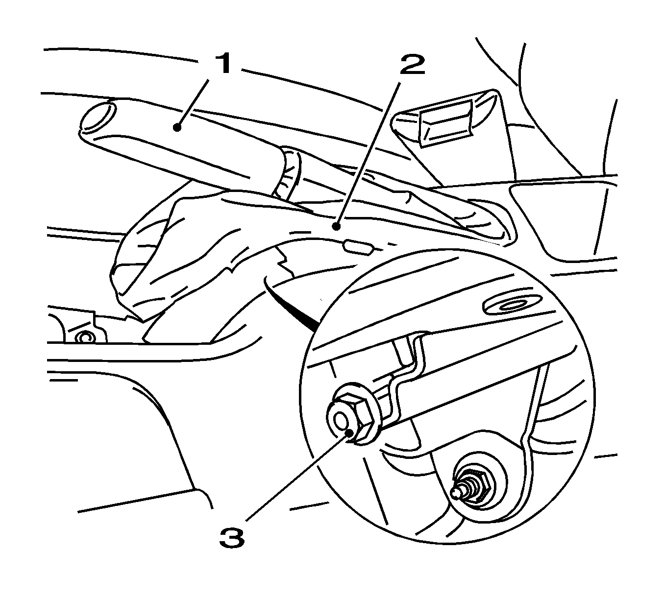
- Detach the boot of the handbrake lever (2).
- Slacken the handbrake cable by turning back the adjusting nut (3).
- Raise and support the vehicle. Refer to Lifting and Jacking the Vehicle.
- Remove the rear wheels. Refer to Tire and Wheel Removal and Installation.
- Push down the 2 operating levers (1) at the brake caliper with a screwdriver.
- Detach the 2 handbrake cables from operating levers.
- Remove the 2 retaining clips (2).
- Detach the 2 handbrake cables from brake caliper.
- Separate the handbrake cables from the restraining clips along the axle.
- Disconnect the restraining brackets holding the wheel speed sensor wires and service brake hoses to the rear axle.
- Disconnect both wheel speed sensors.
- Place a hydraulic lift table under the rear axle.
- Raise the hydraulic lift table.
- Remove the 2 shock absorbers from the rear axle.
- Lower the hydraulic lift table enough to allow for spring removal.
- Remove the 2 springs.
- Remove the 4 damping rings.
- Separate both brake/hub assemblies from the axle by removing the bolts (1) and suspend hub/brake assembly in the wheel wells.
- Mark all body to bracket bolt locations on both rear axle bushing brackets.
- Make sure the hydraulic lift table is supporting the rear axle.
- Remove the 6 bolts from the vehicle underbody.
- Lower the rear axle with the hydraulic lift table.

Note: The brake system remains closed and the brake linings installed.
Note: Ensure that the vehicle does not lift from the lifting platform attachment points.
Remove the 2 bolts.
Note: Note installation position of damping rings.
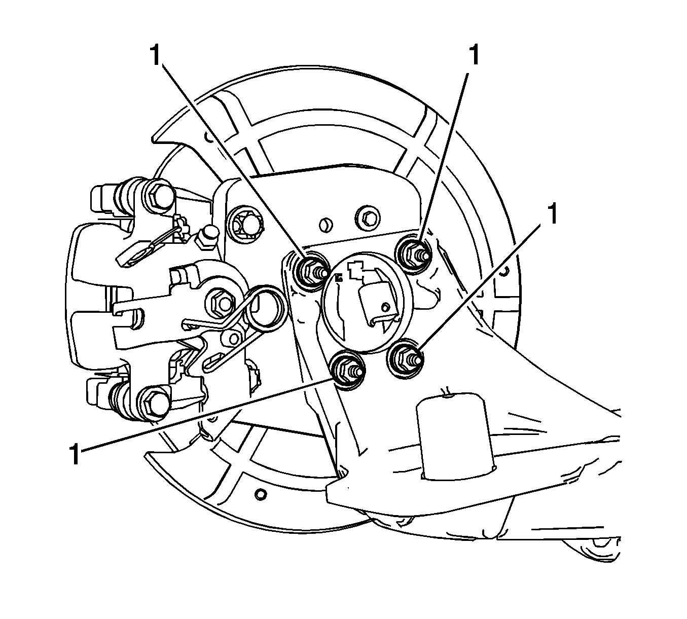
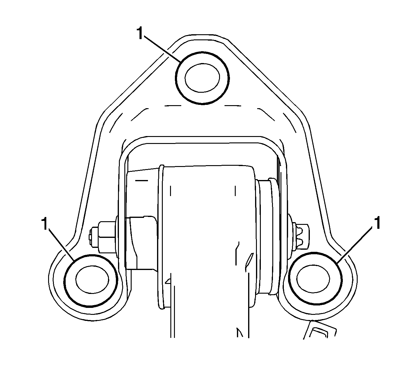
Note: The bolts must not be removed from the rear axle bracket using an impulse or impact screwdriver.
Disassemble Procedure
- Remove the rear axle. Refer to Rear Axle Replacement.
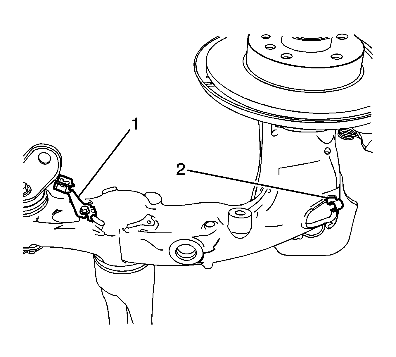
- Remove the handbrake cable brackets (1) and clips (2) from the rear axle.
- Remove bushing through bolts and rear axel bushing bracket.
Assemble Procedure
- Loosely install rear axel bushing bracket and new bushing through bolts.
- Install the handbrake cable brackets and clips to the rear axle.
- Install the rear axle. Refer to Rear Axle Replacement.
Caution: Refer to Fastener Caution in the Preface section.

Tighten
Tighten the bolted handbrake cable brackets to 8 N·m (71 lb in).
Installation Procedure
- Inspect the thread of the cage nuts on the vehicle underbody for damage.
- Install the rear axle to vehicle underbody.
- Align the rear axle by using the previously marked bolt locations.
- Tighten the 6 new bolts on the rear axle bracket on the vehicle underbody.
- Raise the rear axle with hydraulic lift table until a distance of I=173±10 mm is achieved between the spring mounts at the rear axle and the spring mounts at the vehicle underbody.
- If the bolted joint on the rear axle bracket on the damping bush is undone.
- Install the hub/rotor/brake assemblies.
- Reconnect both wheel speed sensors.
- Lower the hydraulic lift table enough to allow for spring installation.
- Install the 4 damping rings to the springs.
- Insert the 2 springs
- Raise the rear axle until both shock absorbers can be attached to rear axle.
- Install the shock absorbers to the rear axle.
- Lower the hydraulic lift table and remove.
- Attach the handbrake cable to the brake caliper.
- Reattach parking brake cables to retaining brackets.
- Reconnect the restraining brackets holding the wheel speed sensor wires and service brake hoses to the rear axle.
- Install the rear wheels. Refer to Tire and Wheel Removal and Installation.
- Lower the vehicle.
- Adjust the handbrake. Refer to Parking Brake Adjustment.
Note: The rear axle bracket bolts must not be installed using an impulse or impact screwdriver.
Loosely install the 6 new bolts.

Tighten
Tighten the rear axle bracket bolts on the vehicle underbody to 90 N·m (67 lb ft), plus 30 degrees, plus 15 degrees.
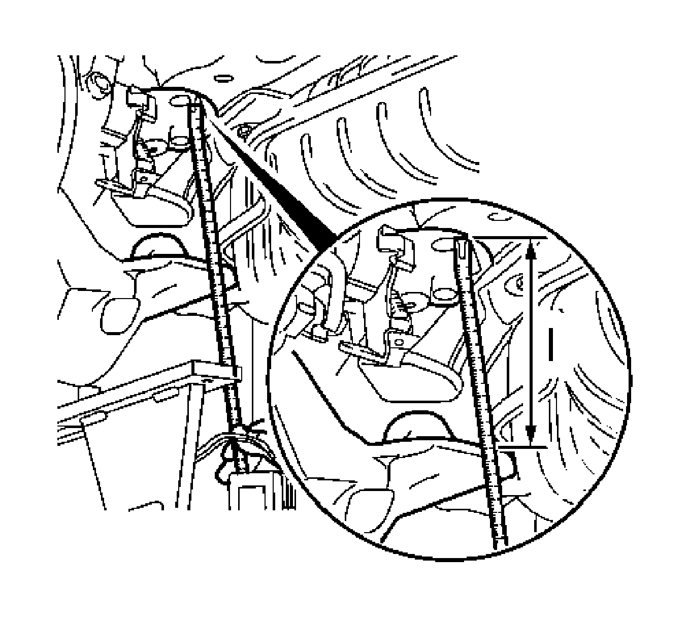
· Distance has to be adjusted on both sides.
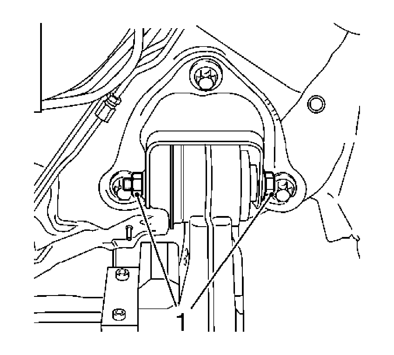
Tighten
Tighten the new bolted joint (1) on the rear axle bracket on the damping bush to 90 N·m (67 lb ft) plus 60 degrees, plus 15 degrees.

Tighten
Tighten the 4 new nuts to 50 N·m (37 lb ft) plus 30 degrees, plus 15 degrees.
Note: Ensure that the vehicle does not lift from the lifting platform attachment points.
Tighten
Tighten the 2 bolts to 130 N·m (96 lb ft).

| • | Insert the 2 handbrake cables into the bracket on the brake caliper. |
| • | Attach the 2 retaining clips (2) to handbrake cable. |
| • | Push down the 2 operating levers (1) at brake caliper with a screwdriver. |
| • | Attach the 2 handbrake cables. |
