For 1990-2009 cars only
Removal Procedure
- Remove the relevant wheel.
- Take the tire off the rim.
- Detach tire valve with tire pressure indicator sensor.
Note: Mark position relative to the wheel hub.
Remove the 5 bolts.

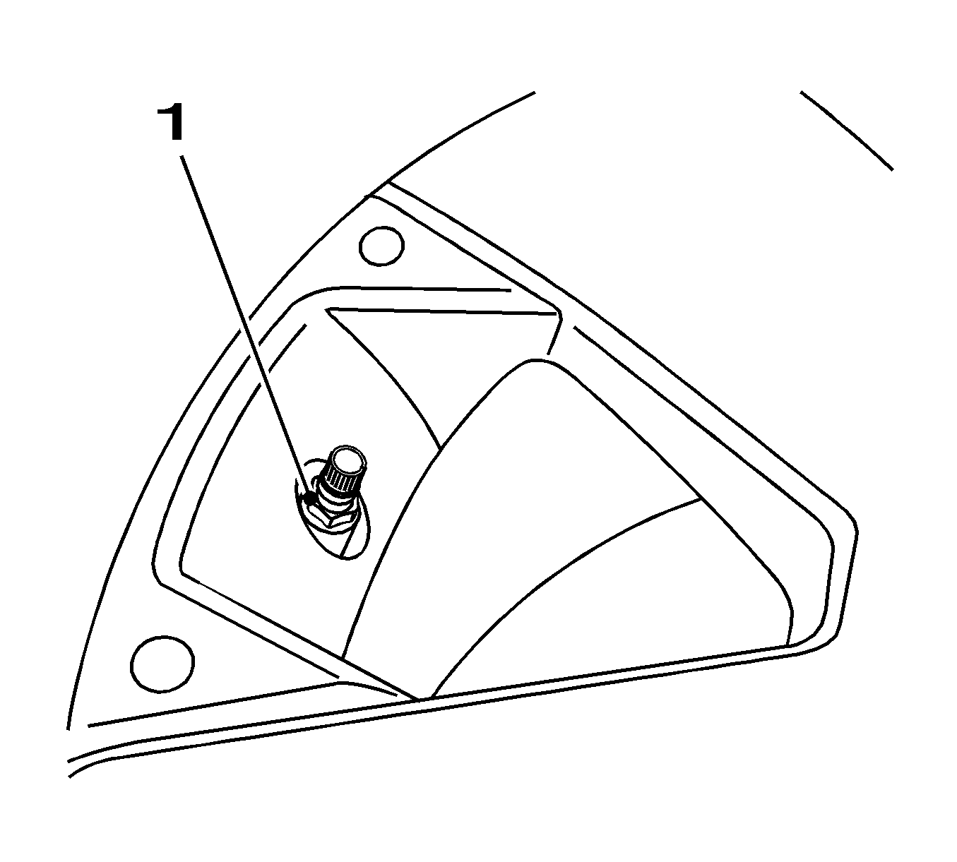
| • | Remove the nut (1). |
| Note: Ensure correct installation position. |
| • | Remove the tire valve with tire pressure indicator sensor. |
Installation Procedure
- Attach the tire valve with tire pressure indicator sensor to rim.
- Install the tire onto the rim and balance it. Refer to Tire and Wheel Assembly Balancing - Off Vehicle and Tire and Wheel Assembly Balancing - On-Vehicle.
- Install the wheel.
Caution: Refer to Fastener Caution in the Preface section.
Note: Ensure correct installation position. The flat side of the valve body must face the hub of the rim.
| 1.1. | Insert the tire pressure indicator sensor with a new sealing ring, valve insert and dust cap. |
| 1.2. | Tighten the nut (1). |
Tighten
Tighten the nut to 9 N·m (80 lb in).

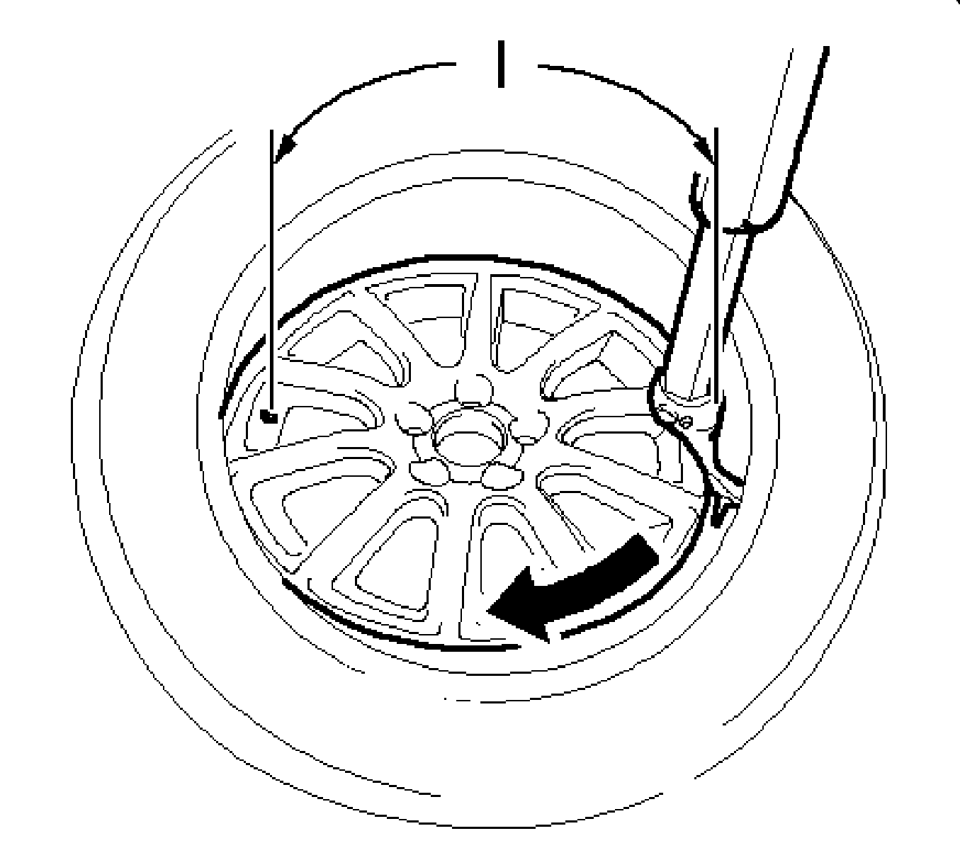
Note: To prevent damage to tire pressure sensor, the tire should be fitted to the rim starting approximately 170 degrees in the fitting direction before the valve when fitting starts (2).
Tighten
Tighten the 5 bolts to 110 N·m (81 lb ft).
