For 1990-2009 cars only
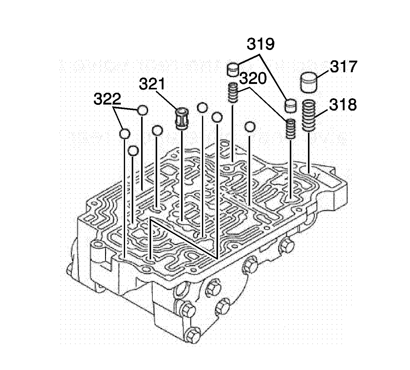
- Install the check valve springs (318, 320), check valves (317, 319).
- Install the fluid strainer (321) and the 7 check balls (322).
- Place the No.1 rear control valve body spacer plate (330) and NEW gaskets (329, 331) on the rear control valve body assembly (323).
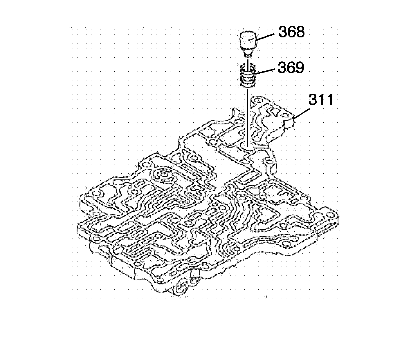
- Install the middle control valve body fluid cooler by-pass valve spring (369) and the middle control valve body fluid cooler by-pass valve (368) into the middle control valve body assembly (311).
- Turn the rear control valve body assembly (323) over and place it on the middle control valve body assembly (311). Align each bolt hole in the valve bodies with the No.1 rear control valve body gaskets (329, 331) and plate (330).
- Place the 3 middle control valve body bolts (365, 366) in the rear valve body.
- Temporarily tighten the 3 middle control valve body bolts (365, 366).
- Place the No.2 rear control valve body assembly spacer plate (327) and NEW No.2 rear control valve body gaskets (326, 328). Align each bolt hole in the valve bodies with the gaskets and plate.
- Place the No.2 rear control valve body assembly (325) on the rear control valve body assembly (323).
- Place the 5 No.2 rear control valve body bolts (362, 363) in the rear valve body.
- Temporarily tighten the 5 No.2 rear control valve body bolts (362, 363).
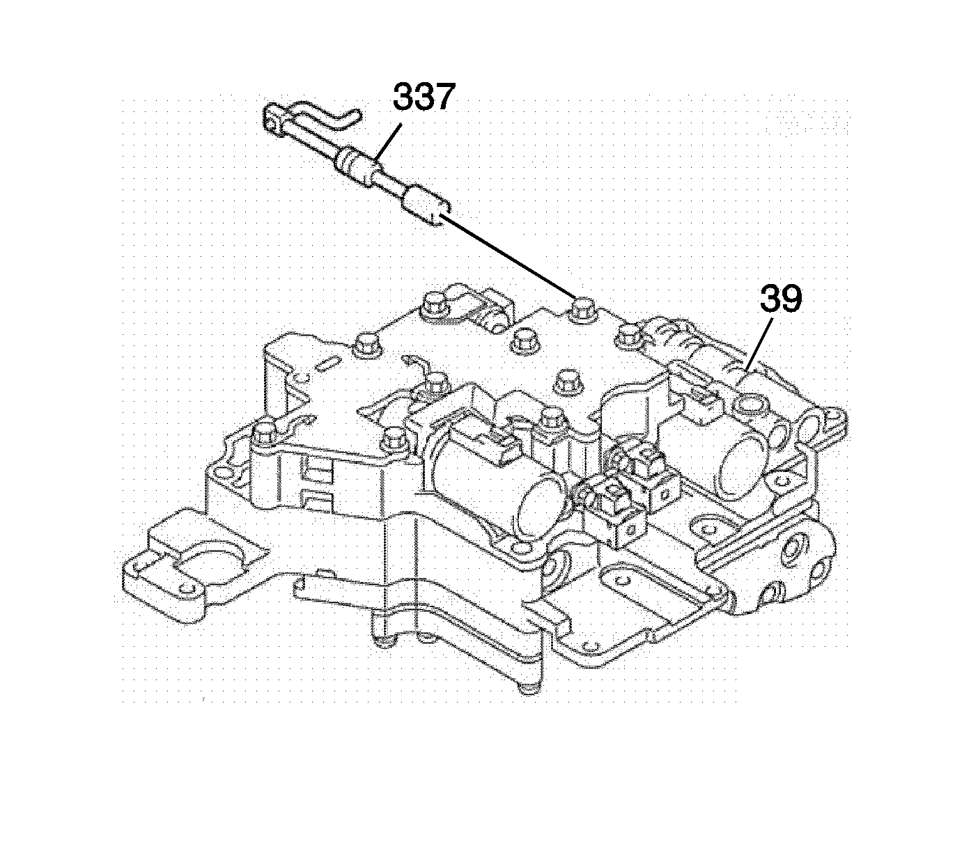
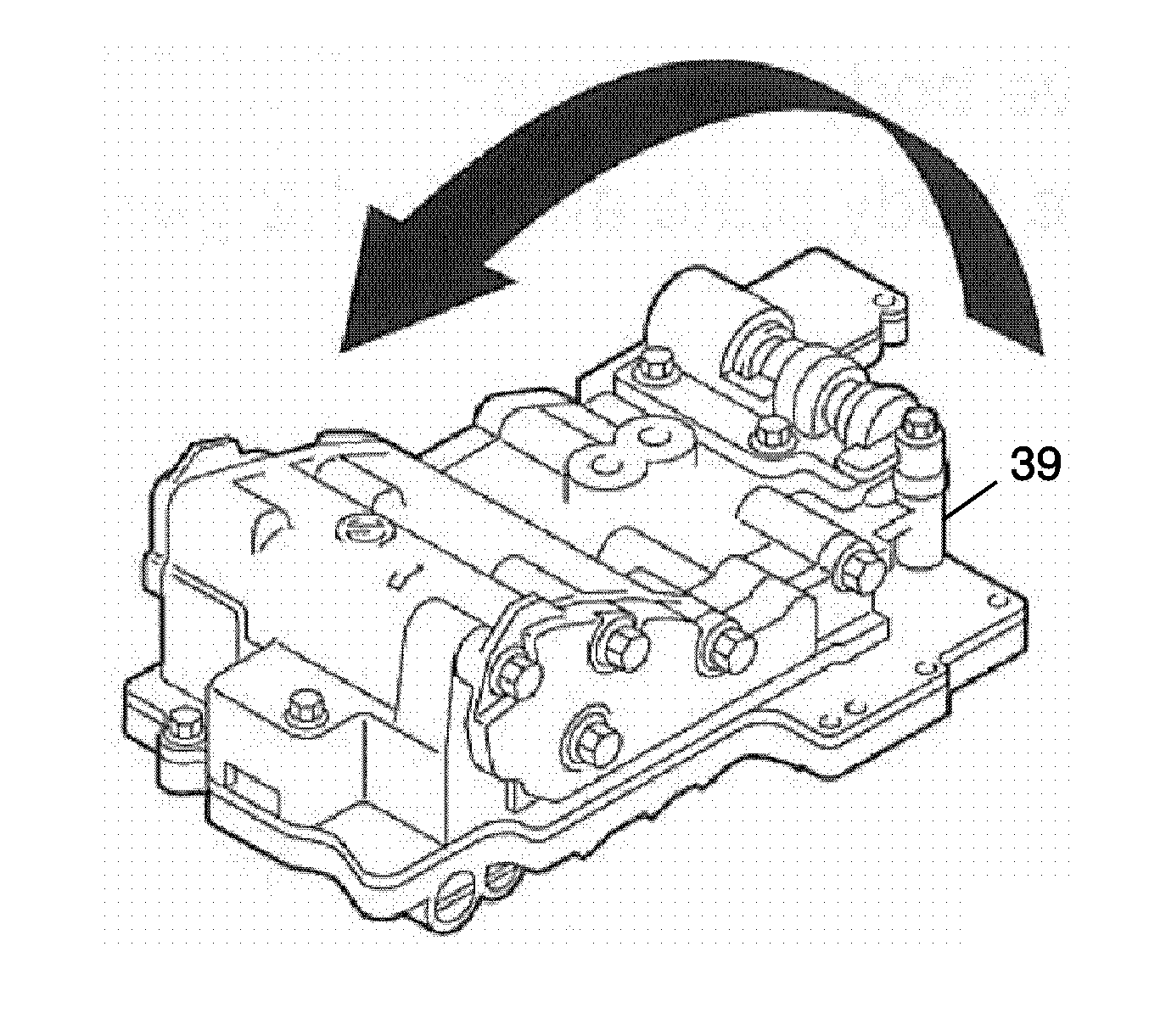
- Turn the transmission control valve body assembly (39) over.
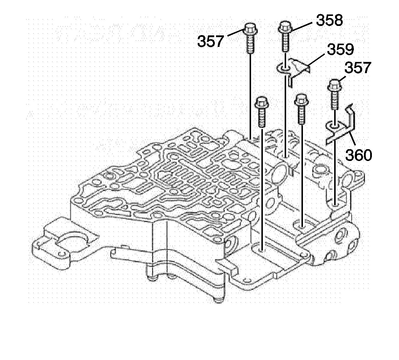
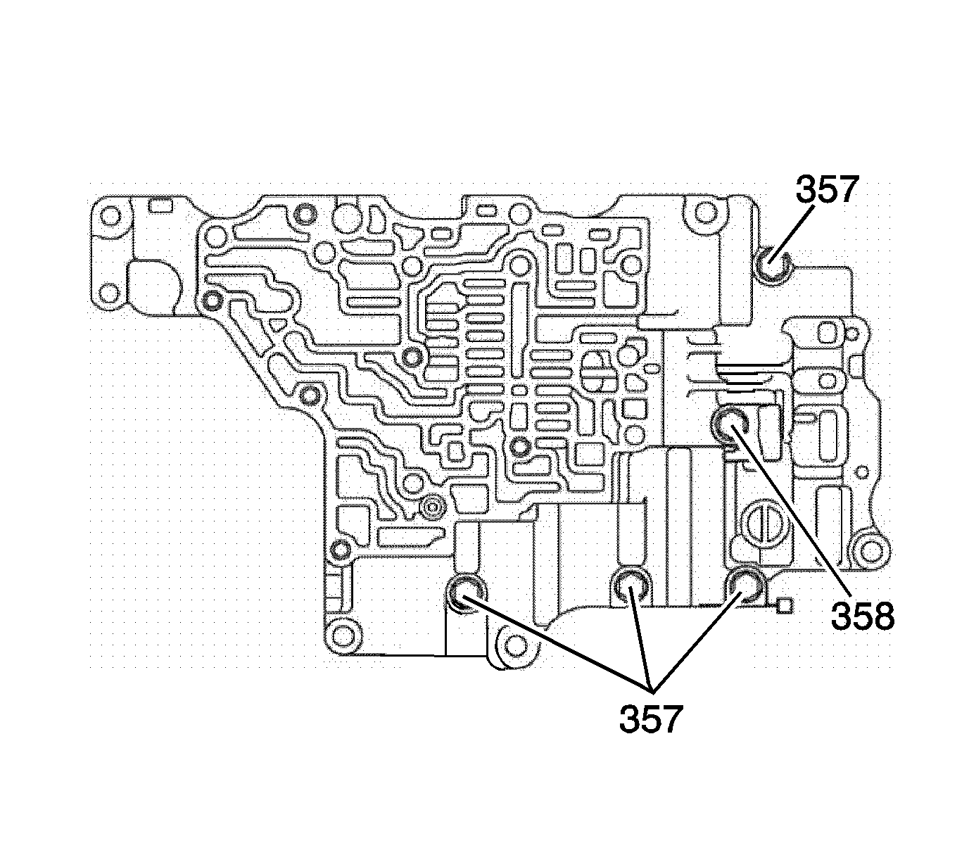
- Place the No.2 rear valve body wiring harness assembly retainer (360) and the No.2 rear valve body fluid baffle (359) with the 5 rear valve body bolts (357, 358).
- Temporarily tighten the 5 rear valve body bolts (357, 358).
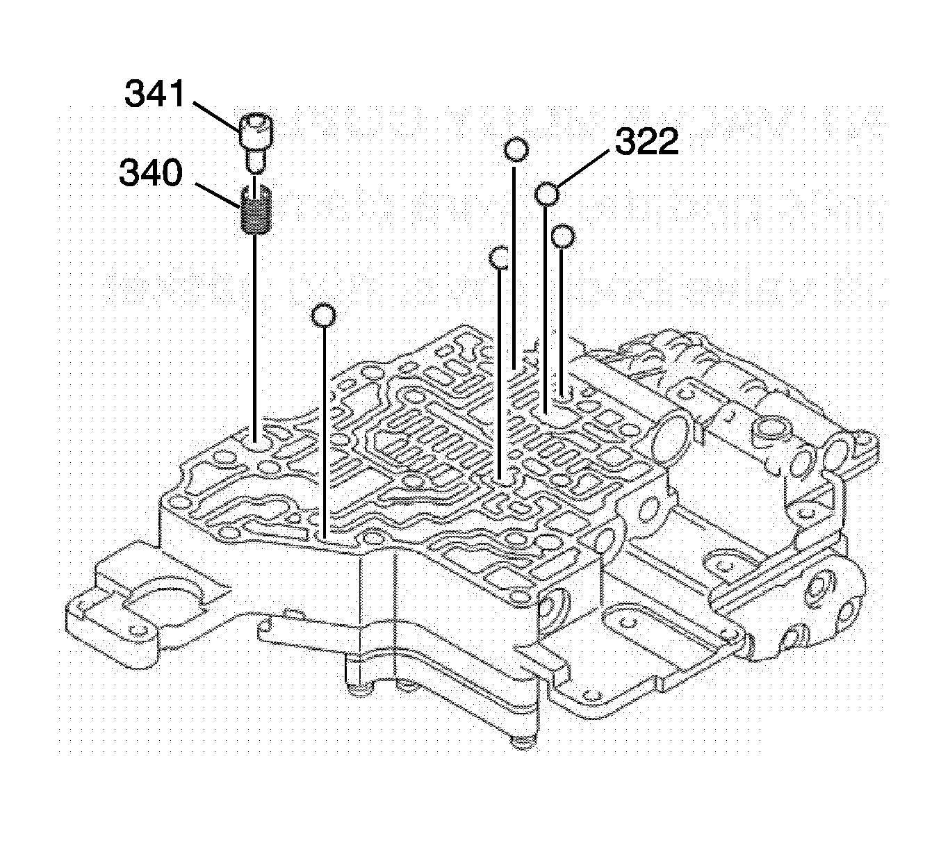
- Install the 5 check balls (322).
- Install the pressure relief valve spring (340) and the pressure relief valve (341).
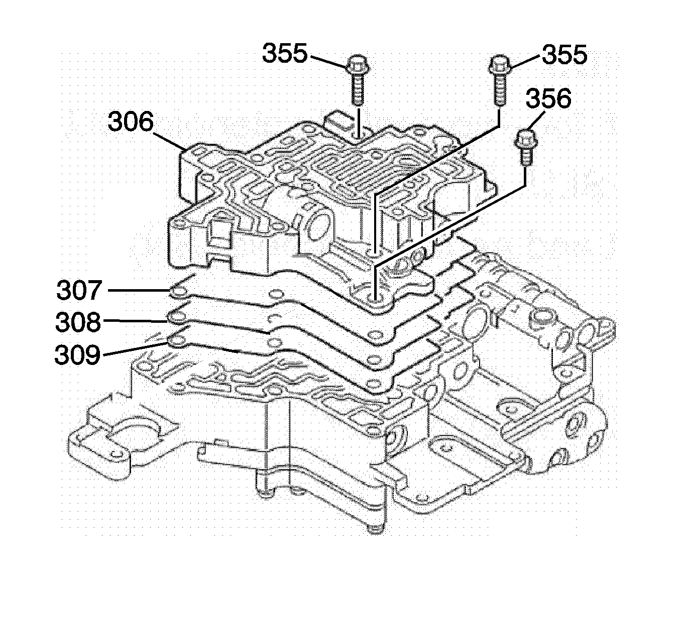
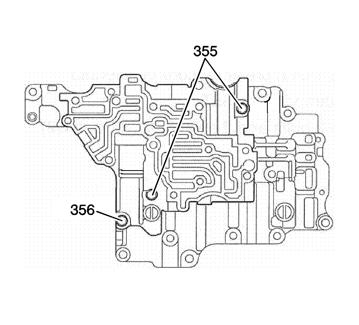
- Place the front control valve body spacer plate (308) and NEW front control valve body spacer plate gaskets (355, 356) onto the front control valve body (306).
- Temporarily tighten the 3 front valve body bolts (355, 356).
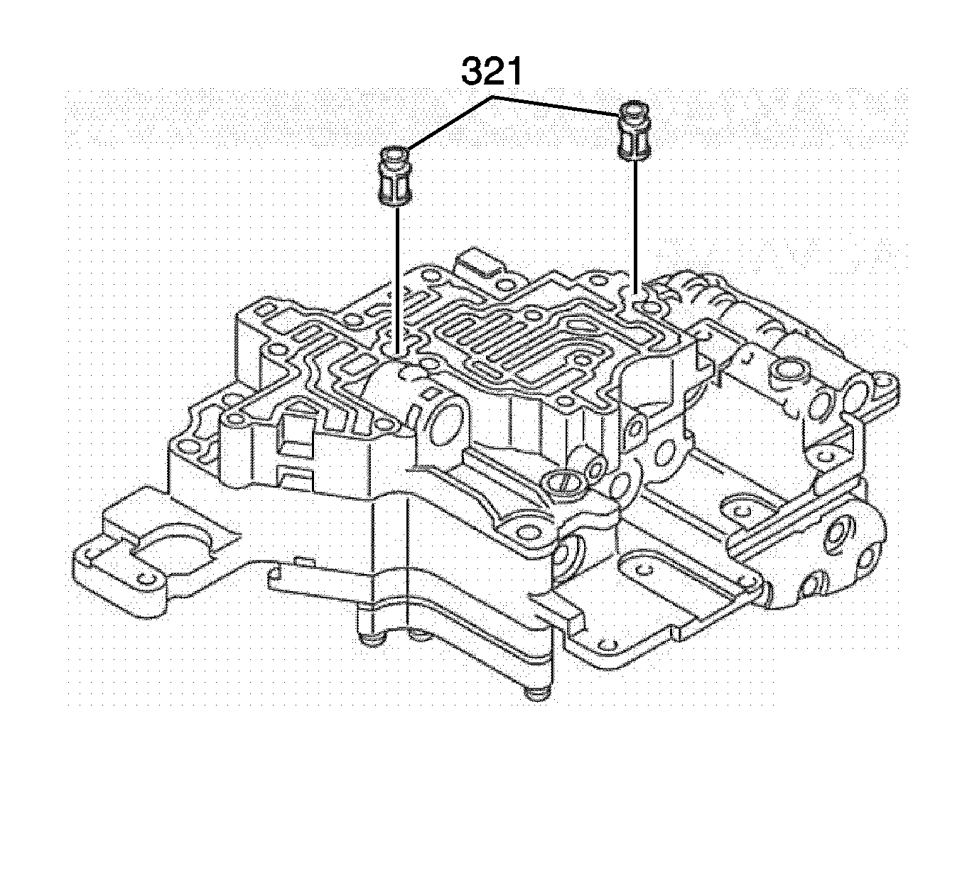
- Install the 2 fluid strainers (321).
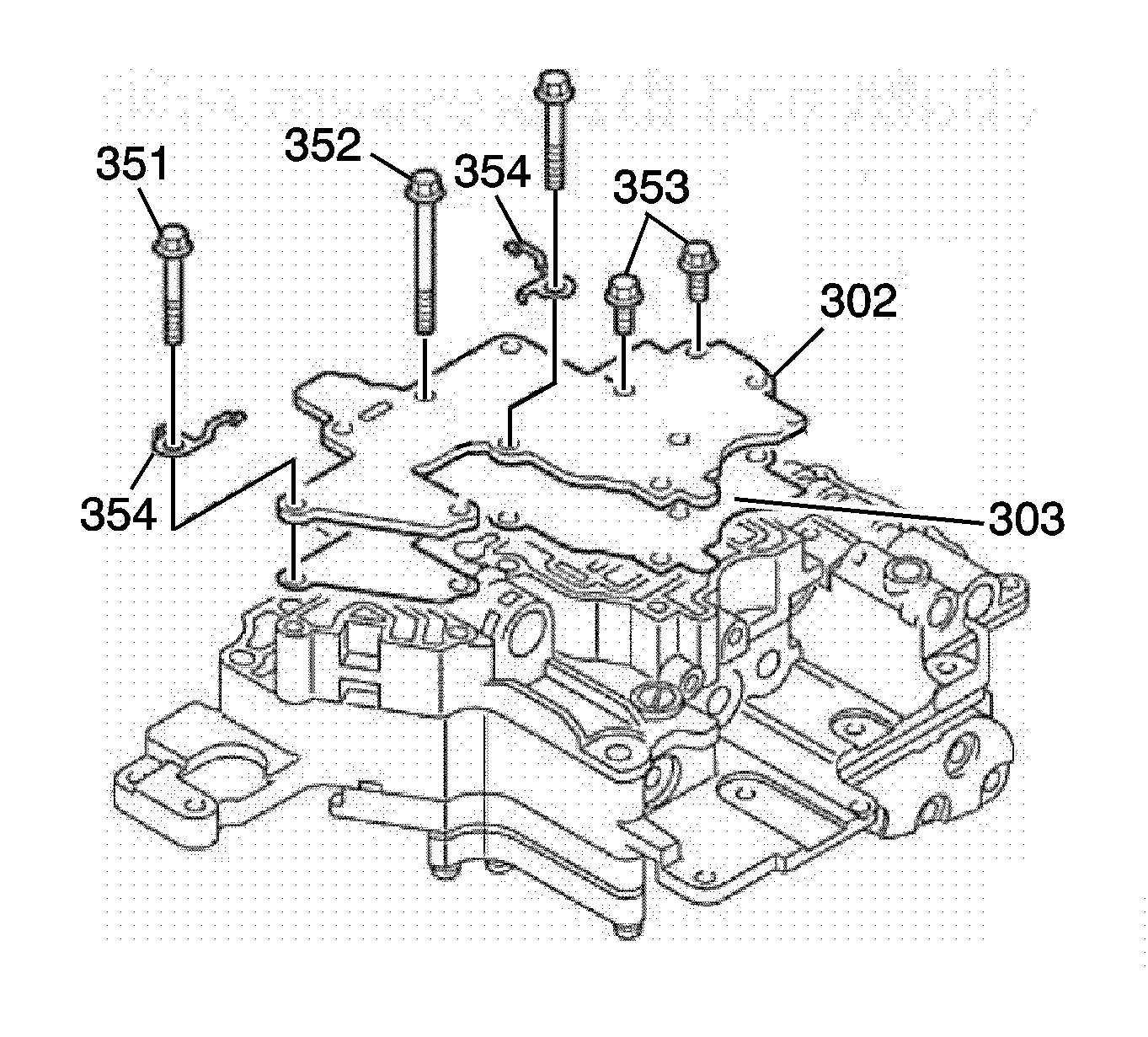
- Install the front control valve body cover (302) and a NEW front control valve body cover gasket (303).
- Install the 2 wiring harness assembly retainers (354).
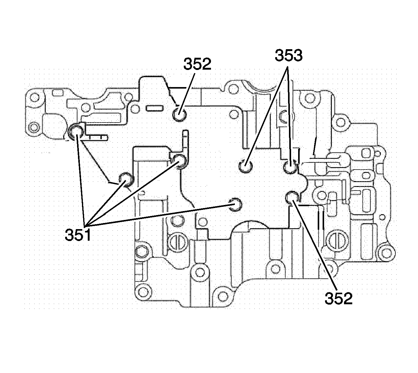
- Place the 8 front control valve body cover bolts (351, 352, 353) onto the assembly.
- Temporarily tighten the 8 front control valve body cover bolts (351, 352, 353).
- Tighten the 24 bolts on the front control valve body cover, front control valve body (306), middle control valve body assembly , rear control valve body assembly and No.2 rear control valve body assembly. Tighten bolts to 6.7 N·m (59 lb in).
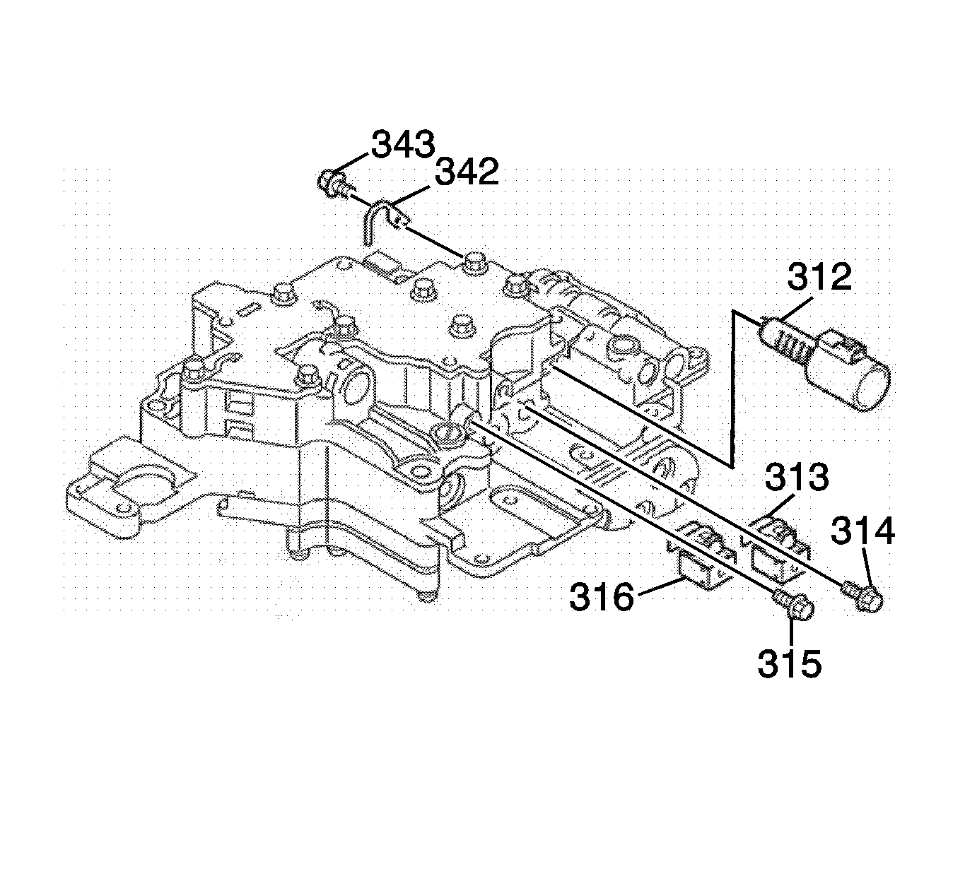
- Install the 2-3 shift solenoid valve assembly S1 (313) and the 2-3 shift solenoid valve assembly bolt (314).
- Install the 1-2/3-4 shift solenoid valve assembly S2 (316) and the shift solenoid valve assembly bolt (315). Tighten bolts to 6.7 N·m (59 lb in).
- Install the line pressure control solenoid valve assembly SLT (312), the line pressure control solenoid valve retainer (342) and the 1 line pressure control solenoid valve retainer bolt (343). Tighten bolt to 6.7 N·m (59 lb in).
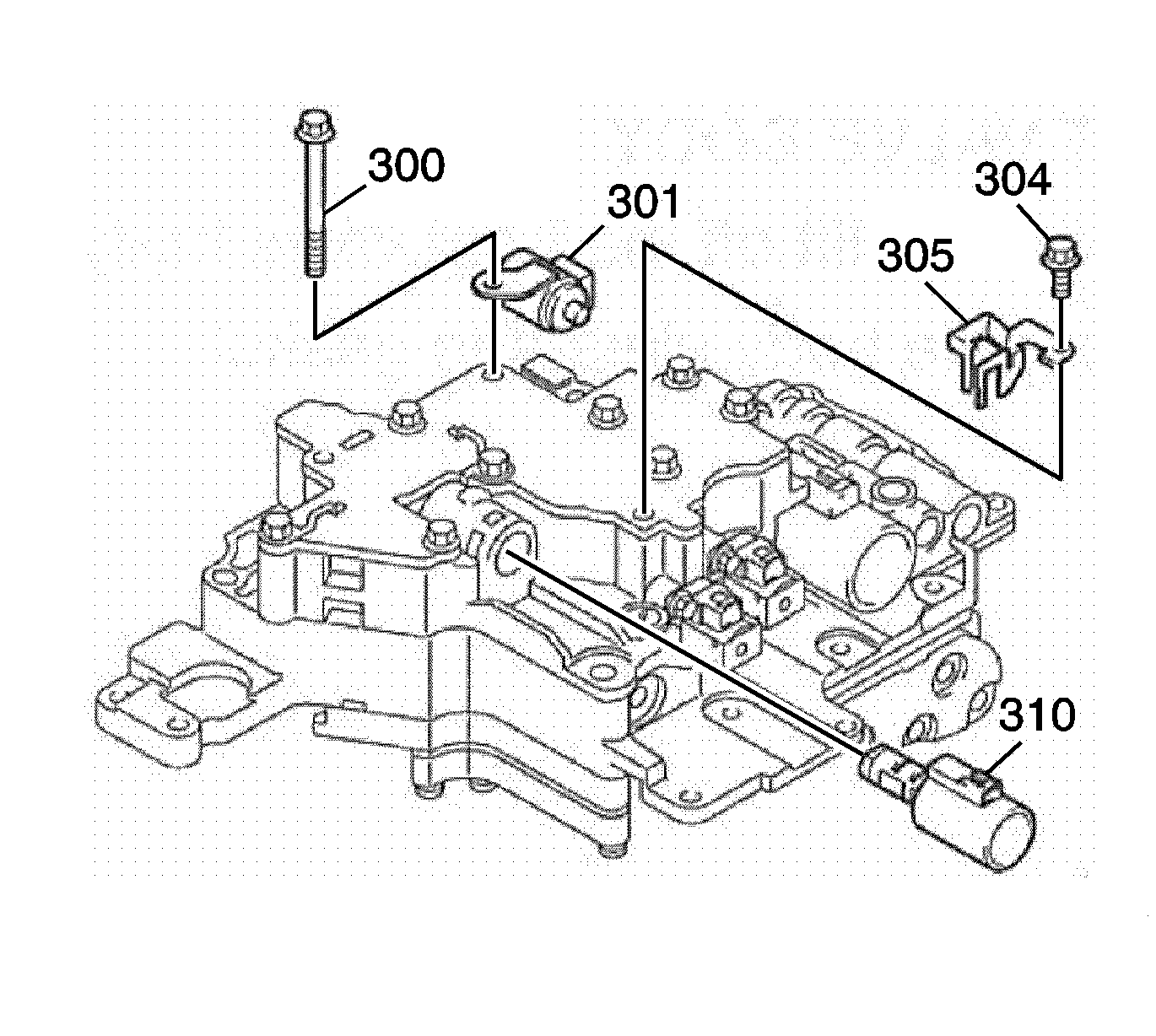
- Install the neutral switching solenoid valve SN (301) and the 1 control valve body bolt (300). Tighten bolt to 6.7 N·m (59 lb in).
- Install the lock up control solenoid SLU (310), the lock up control solenoid clamp (305) and the 1 lock up solenoid clamp bolt (304). Tighten bolt to 6.7 N·m (59 lb in).
- Install the manual valve (337).
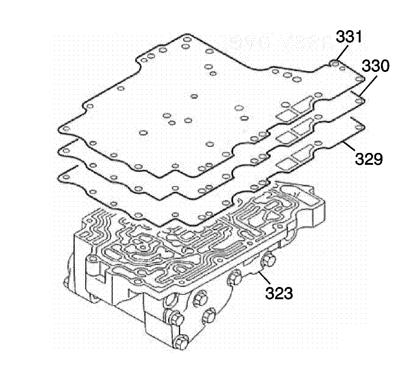
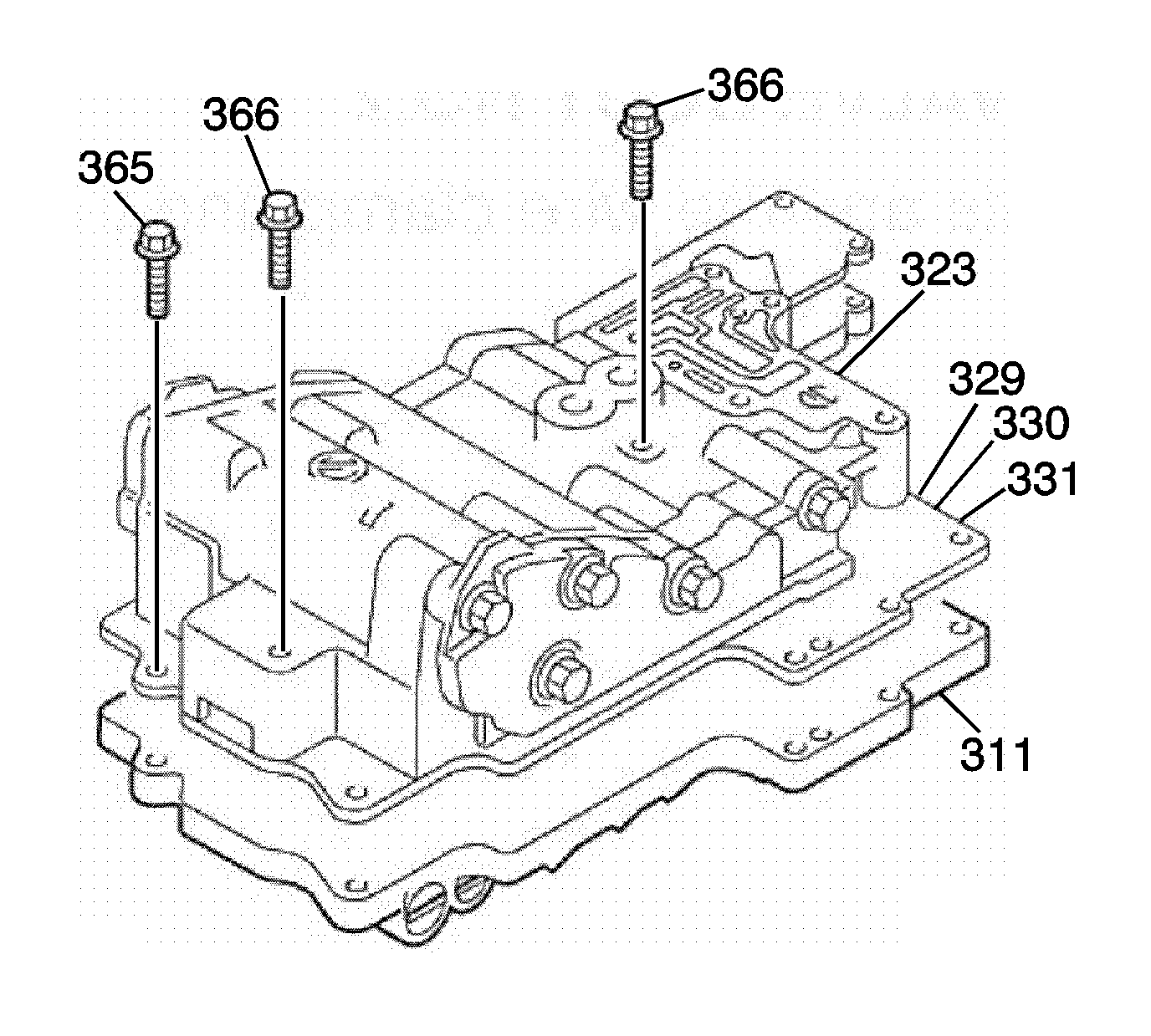
Note: Hold the rear valve body, gaskets and plate securely so they do not separate.
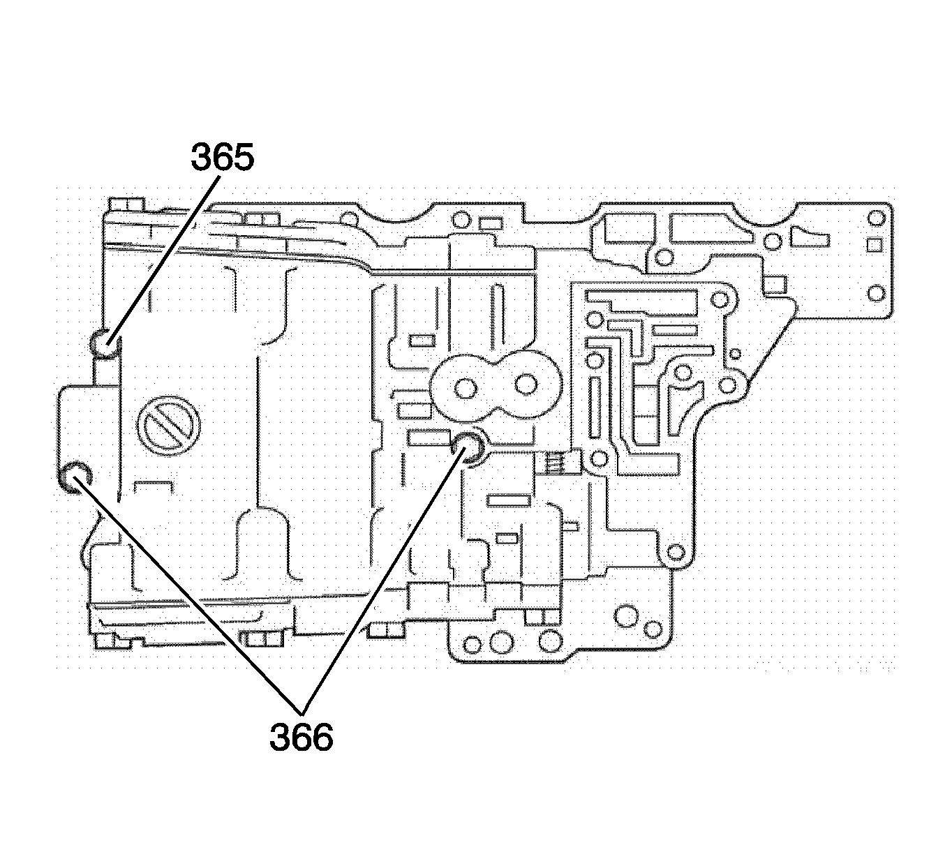
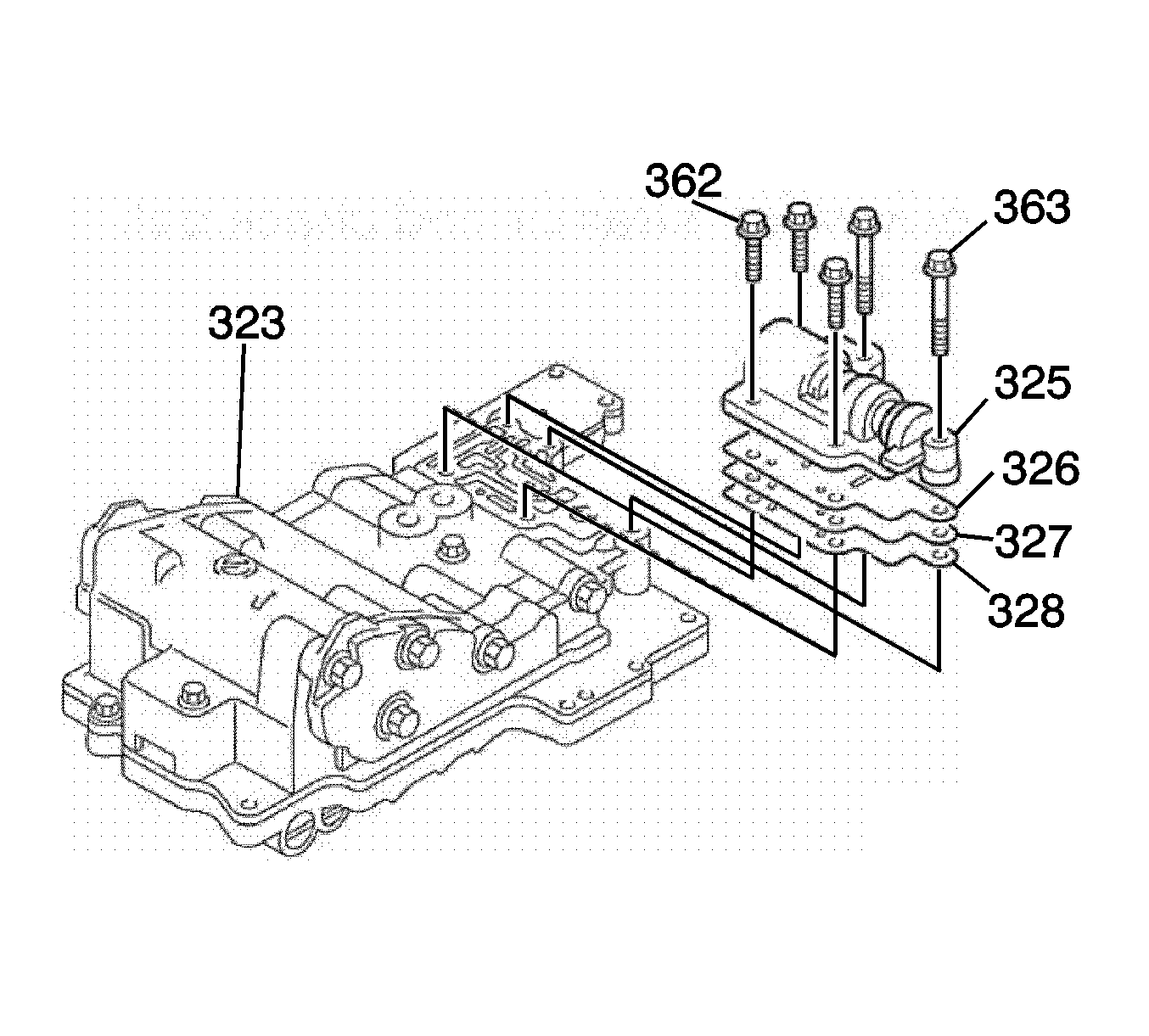
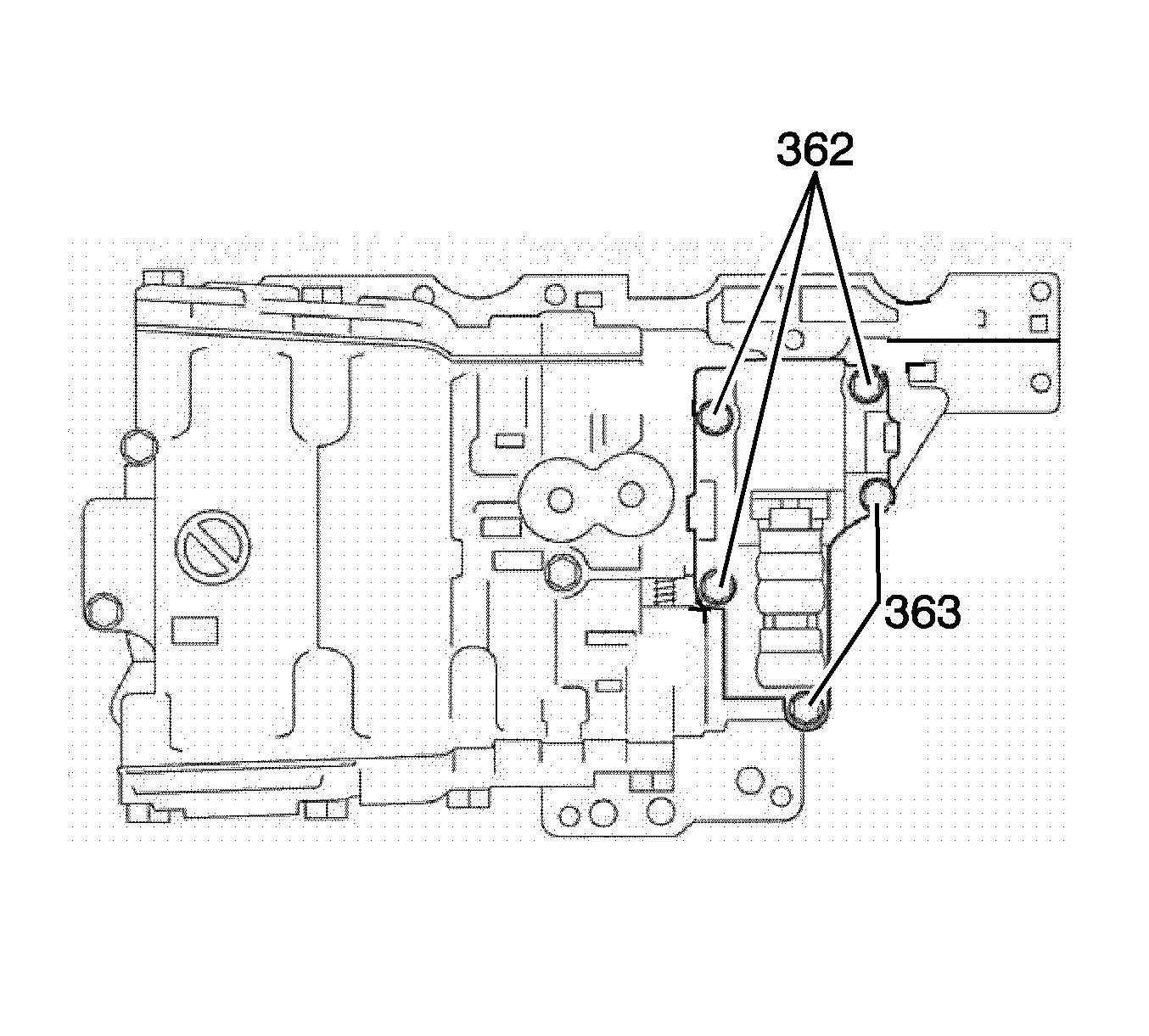
Caution: Refer to Fastener Caution in the Preface section.
Note: Be careful not to damage the O-ring.
Note: Be careful not to damage the O-ring.
