Removal Procedure

Note: The selector lever on the transmission must engage in each case: P (most forward position) (2), R, N (1), D, 3, 2, 1.
- Move the selector lever through all the positions and back again.
| • | Change the gear from P to 1. |
| • | Change the gear from 1 to P. |
Warning: Refer to Battery Disconnect Warning in the Preface section.

- Remove the battery.
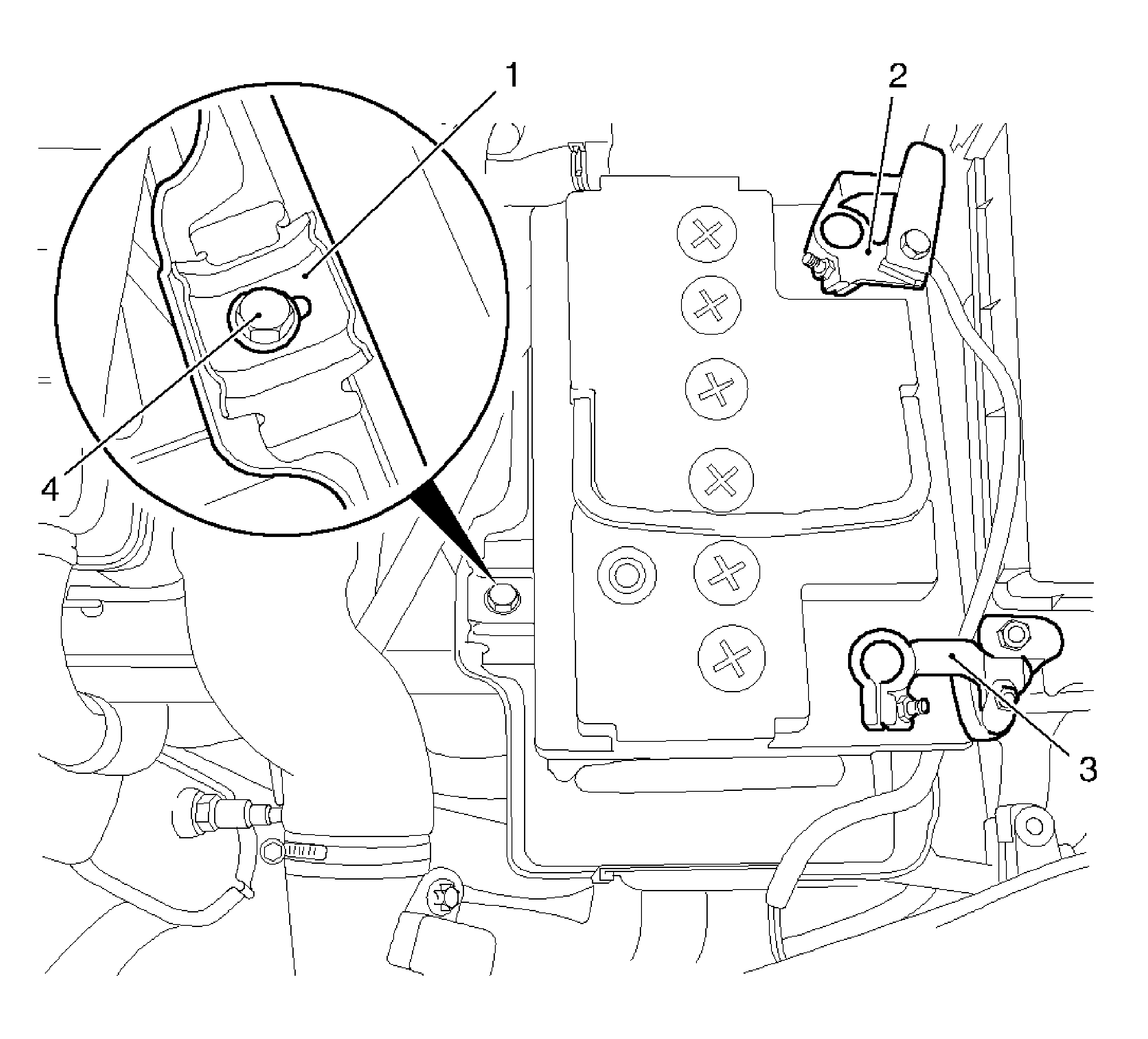
| • | Disconnect the negative cable (2) from the battery. |
| • | Disconnect the positive cable (3) from the battery. |
| • | Remove the bracket (1). |

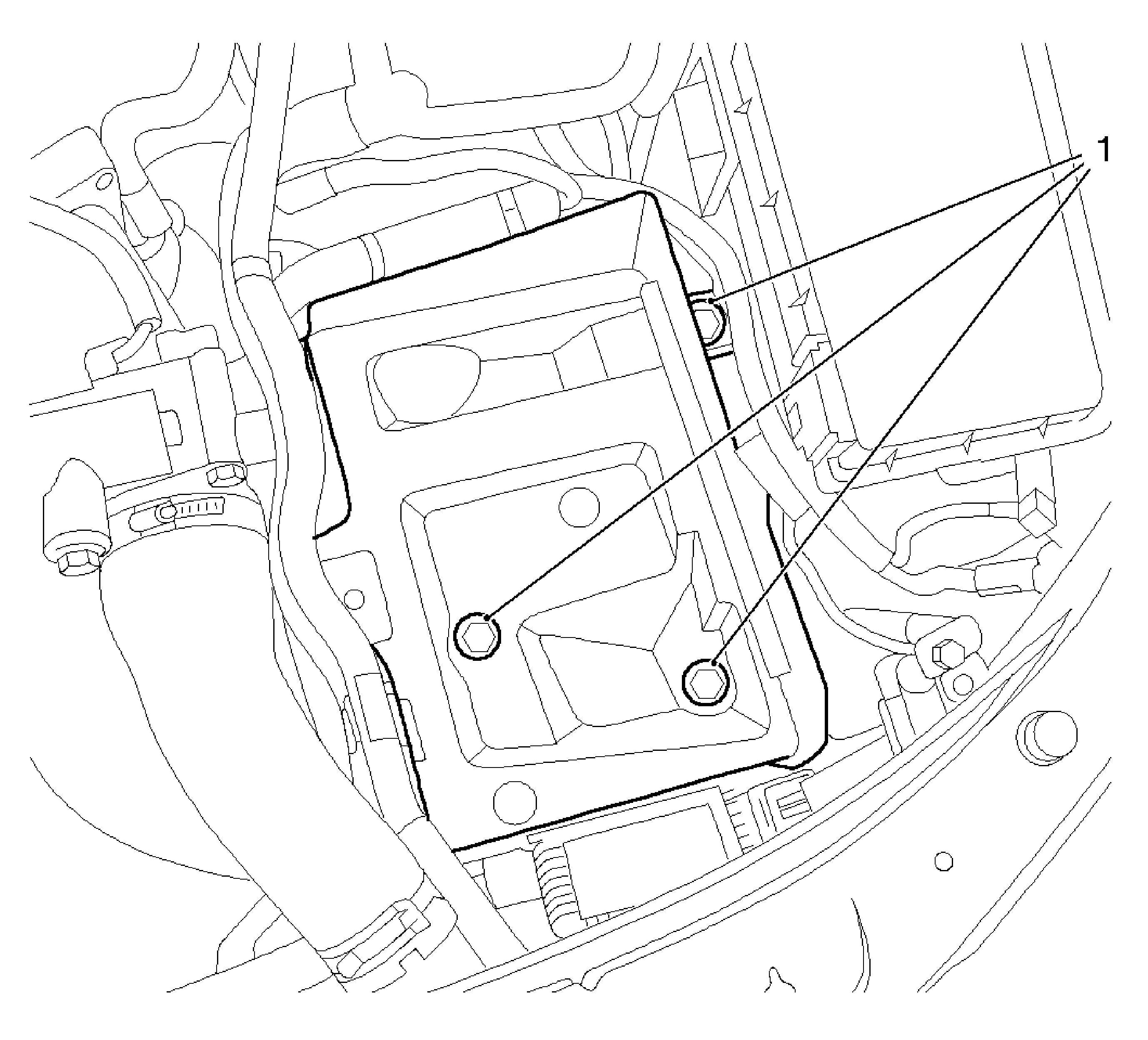
- Remove the battery tray.
| • | Remove the 3 bolts (1). |

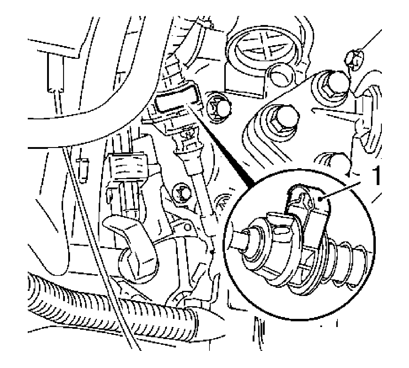
- Open the locking clamp (1) on the selector cable.
Open upward with a small screwdriver.
Installation Procedure

Note: Ensure that the selector lever engages correctly in the P position by moving the selector lever forwards and backwards without pressing the locking button.
- Adjust the selector cable.
| • | Move the selector lever to the P position. |
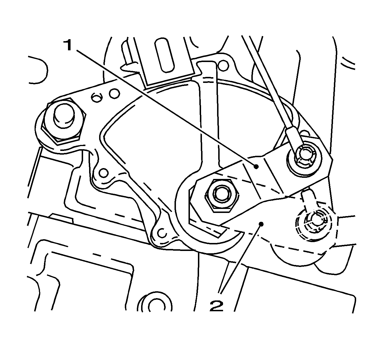
| • | Turn the selector lever (1) on the transmission as far as the stop (position P) (2). |
| • | Engage the pawl in parking lock wheel. |

- Tighten the locking clamp (1) on the selector cable.
Press downwards.
Caution: Refer to Fastener Caution in the Preface section.

- Install the battery tray.
Fasten the cable tie.
Tighten
Tighten the 3 bolts to 10 N·m (89 lb in).

- Install the battery.
| • | Install the bracket (1). |
Tighten
Tighten the bolt (4) to 15 N·m (11 lb ft).
| • | Connect the positive cable (3) to the battery. |
| • | Connect the negative cable (2) to the battery. |
- For programming procedures, refer to
Control Module References.


