Special Tools
| • | J 23327 Clutch Spring Compressor |
| • | SA9179NE Dial Indicator |
For equivalent regional tools, refer to
Special Tools.
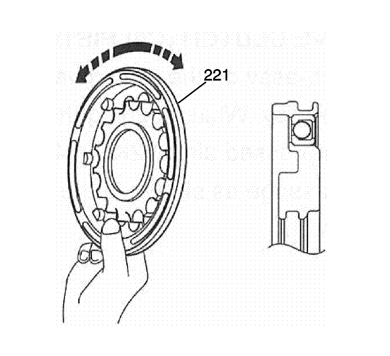
- Inspect the check ball is free by shaking the coast clutch piston (221).
- Inspect the valve does not leak by applying low-pressure compressed air.
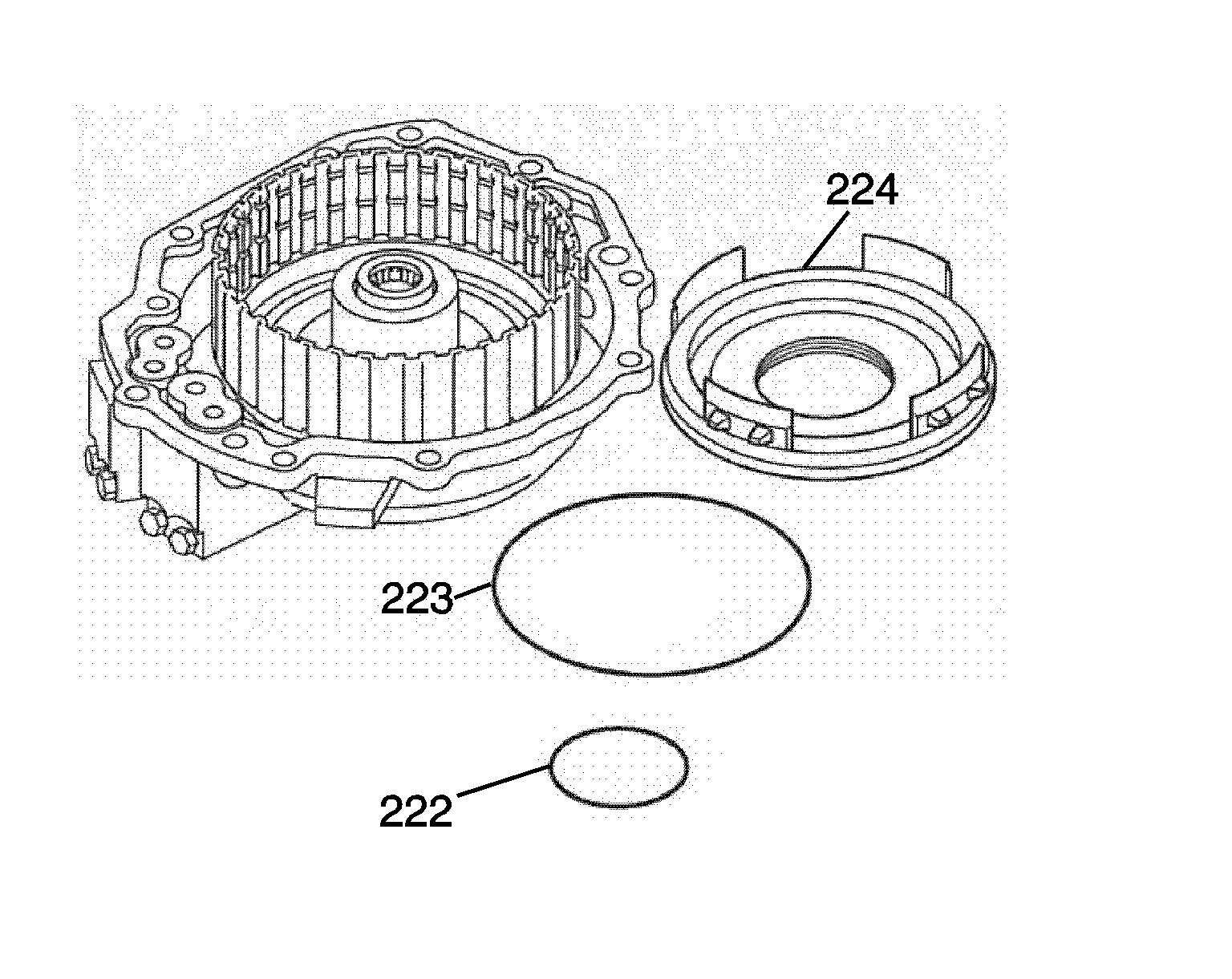
- Coat the overdrive clutch piston inner and outer seals (222, 223) with ATF and install them on the overdrive clutch piston (224).
- Coat the inner surface of the overdrive and coast clutch housing with ATF.
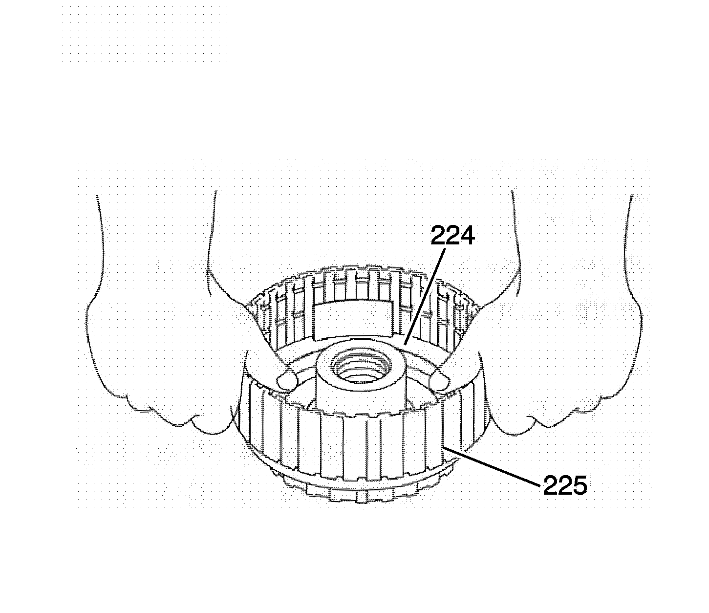
- Press the overdrive clutch piston (224) in the overdrive and coast clutch housing (225), being careful not to damage the O-ring.
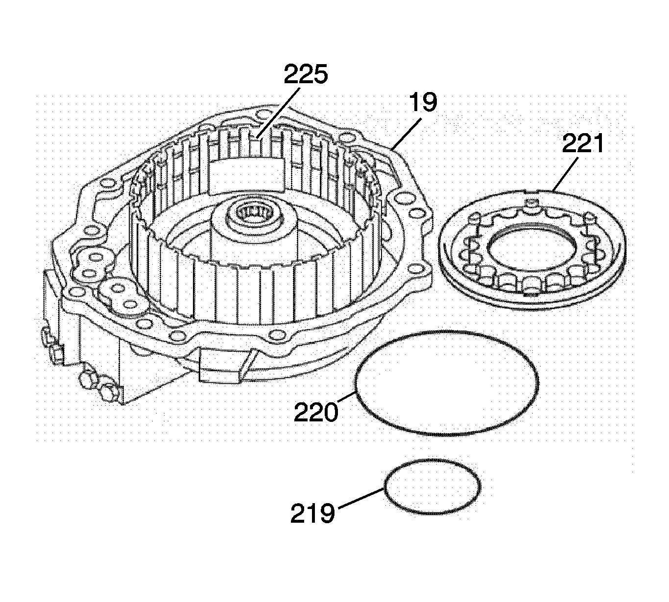
- Coat the coast clutch piston inner and outer seals (219, 220) with ATF and install them on the coast clutch piston (221).
- Coat the inner surface of the overdrive clutch piston with ATF.
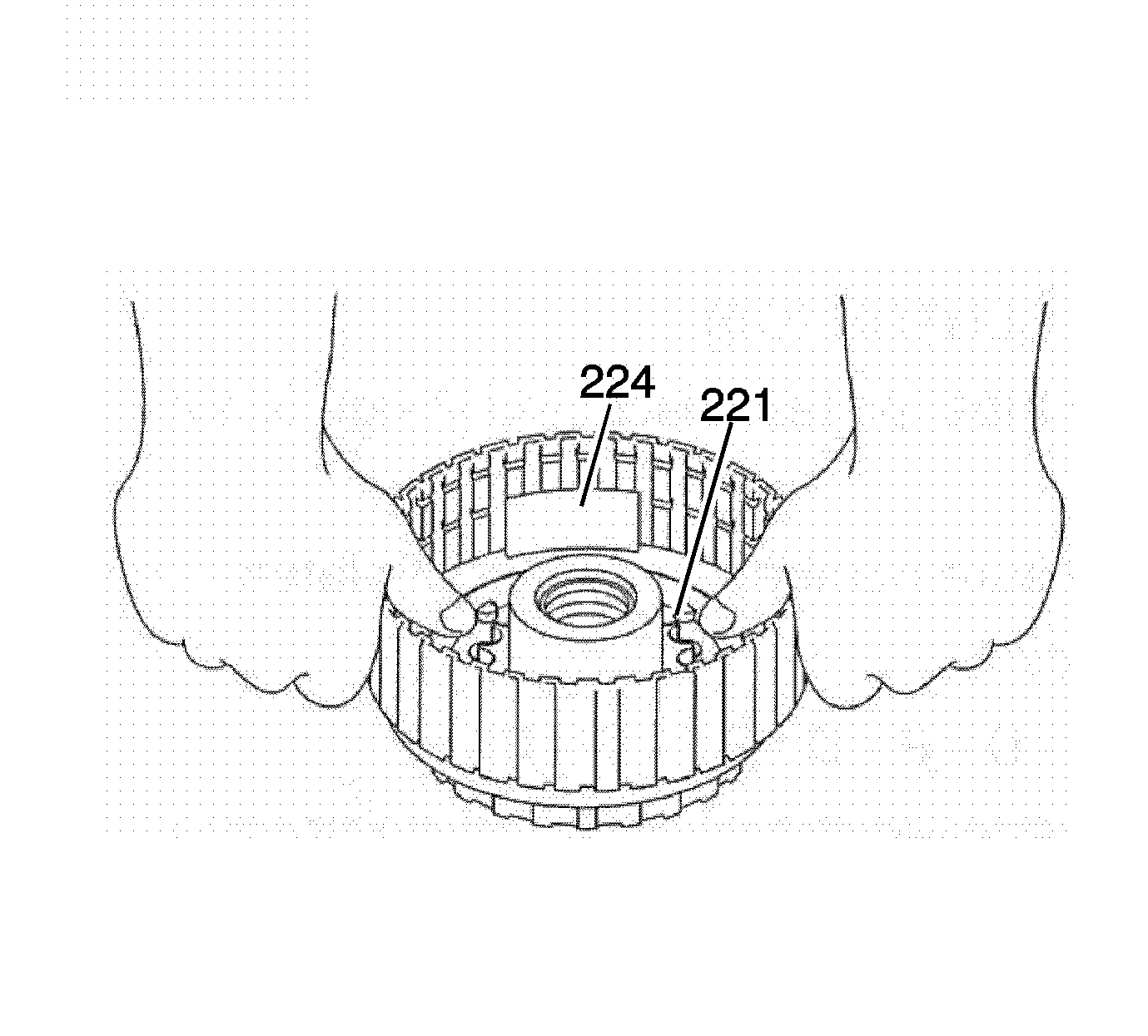
- Press the coast clutch piston (221) into the overdrive clutch piston (224).
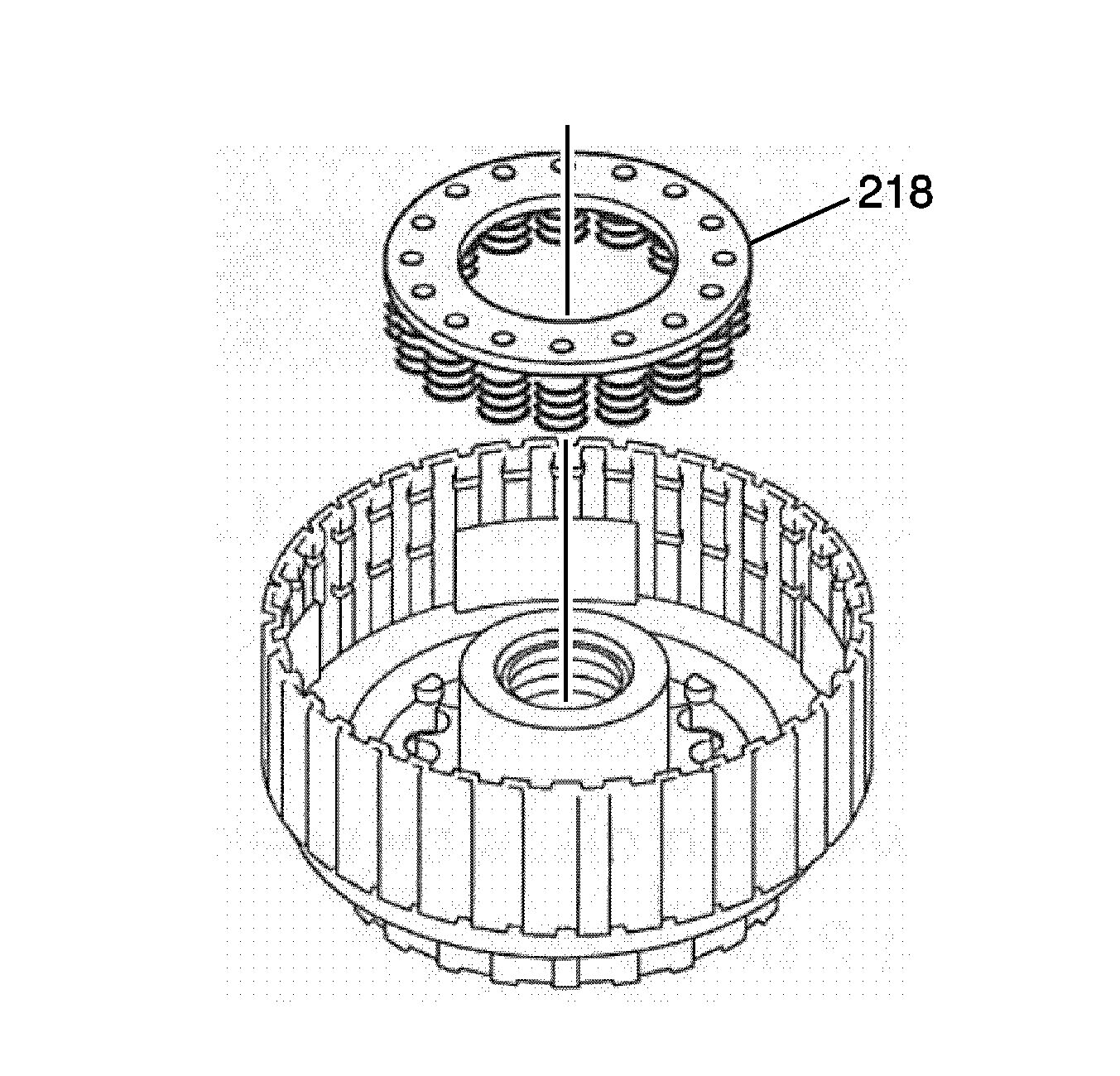
- Place the overdrive coast clutch spring (218) on the coast clutch piston (221).
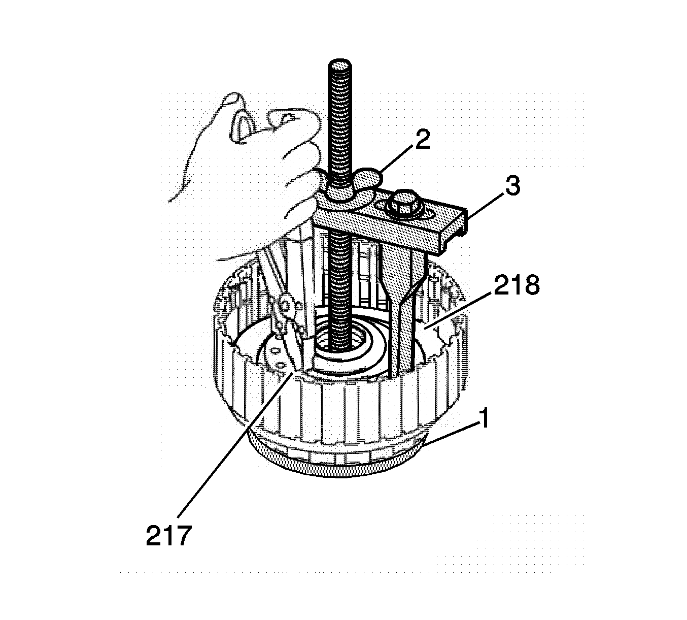
Note: Be sure the end gap of the retaining ring is not aligned with the spring retainer claw.
- Using the bridge and legs of the
J 45124 removal bridge
(3) with the forcing screw of the
J 23327 spring compressor
(2) and J 21420-2 (1) plate, which is part of
J 23327 spring compressor
, compress the overdrive and coast clutch spring (218).
- Install the overdrive and coast clutch spring retaining ring (217). Remove the tools.
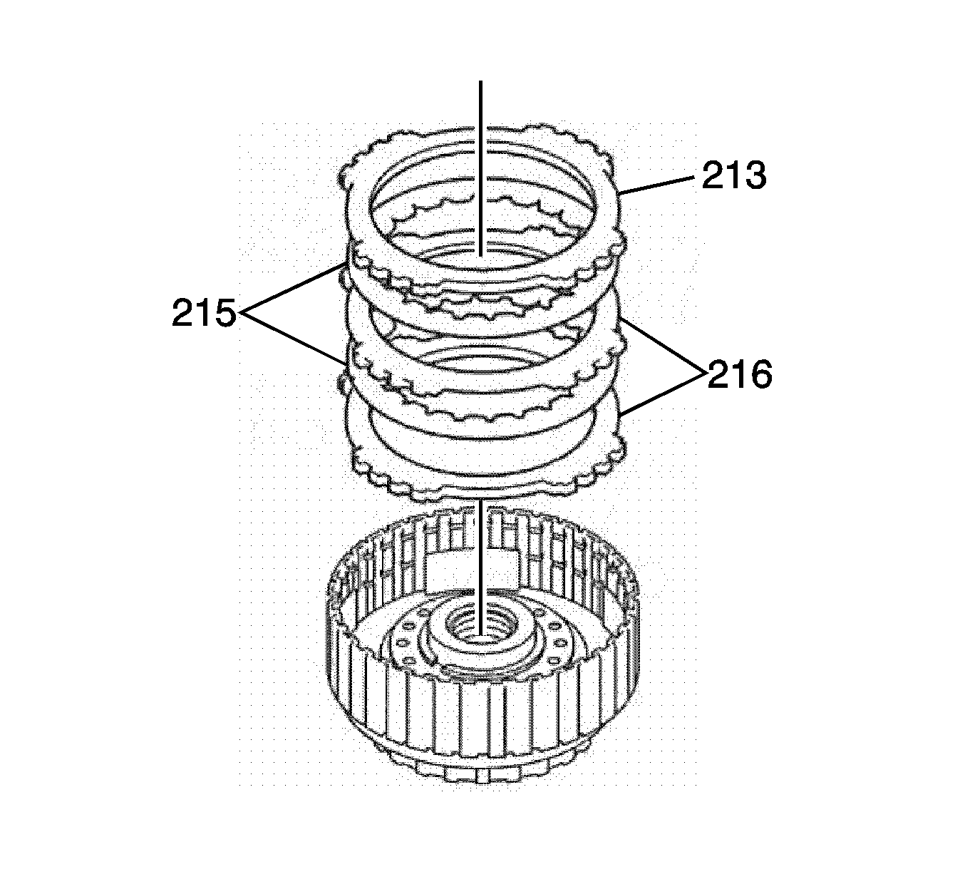
Note: Be sure to alternate the order of plates-2 and discs-2.
- Install the coast clutch backing plate (213), coast clutch plate assembly-steel plates (216) and fiber discs (215) as shown.
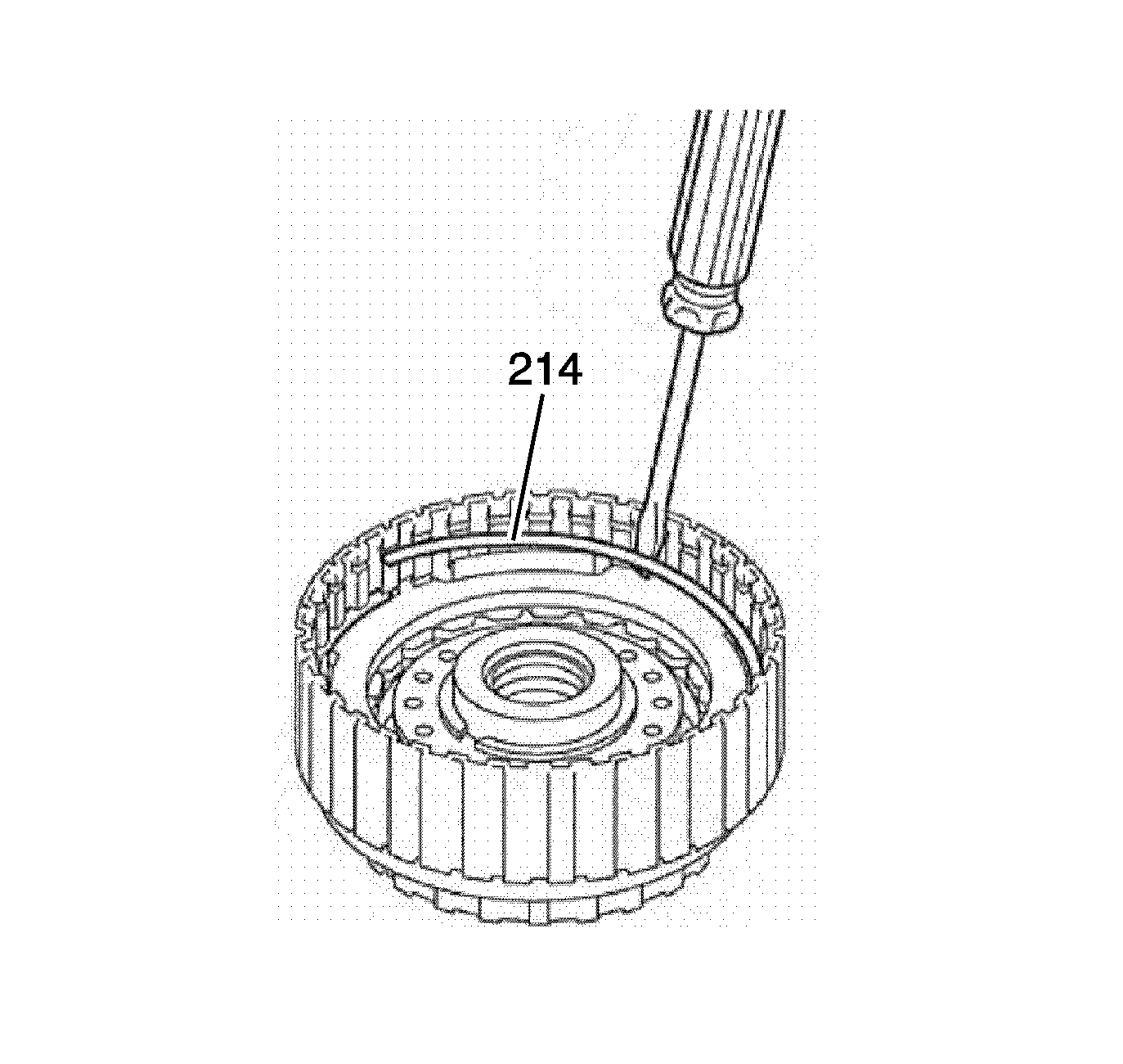
- Install the coast clutch backing plate retaining ring (214) with a screwdriver in the groove. Inspect the end gap of the retaining ring is not aligned with one of the cut-outs.
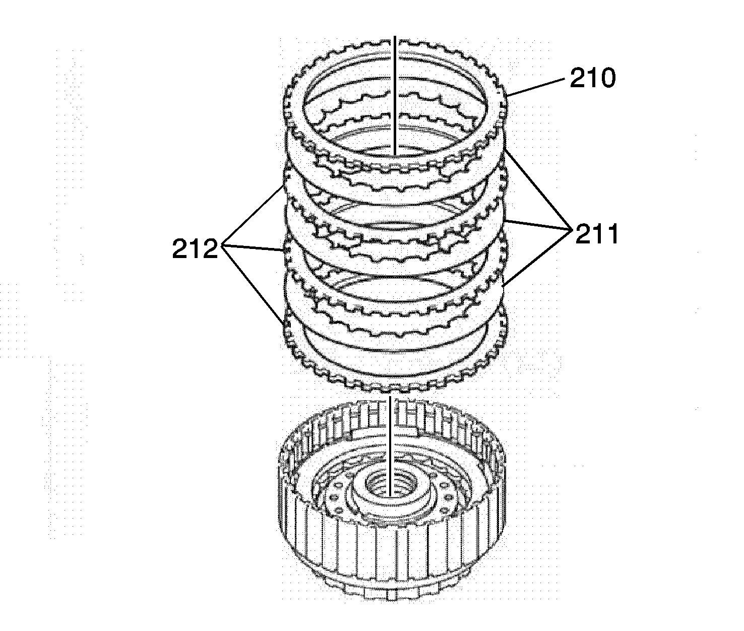
Note: Be sure to alternate the order of plates-3 and discs-3.
- Install the overdrive clutch plate assembly-steel plates (212), fiber discs (211) and the overdrive clutch backing plate (210).
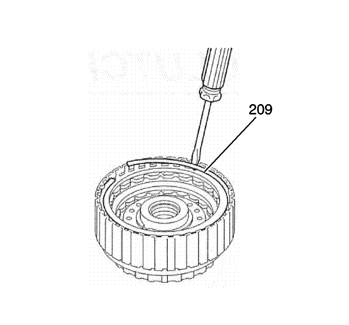
- Install the overdrive clutch backing plate retaining ring (209) with a screwdriver in the groove. Inspect the end gap of the retaining ring is not aligned with one of the cut-outs.
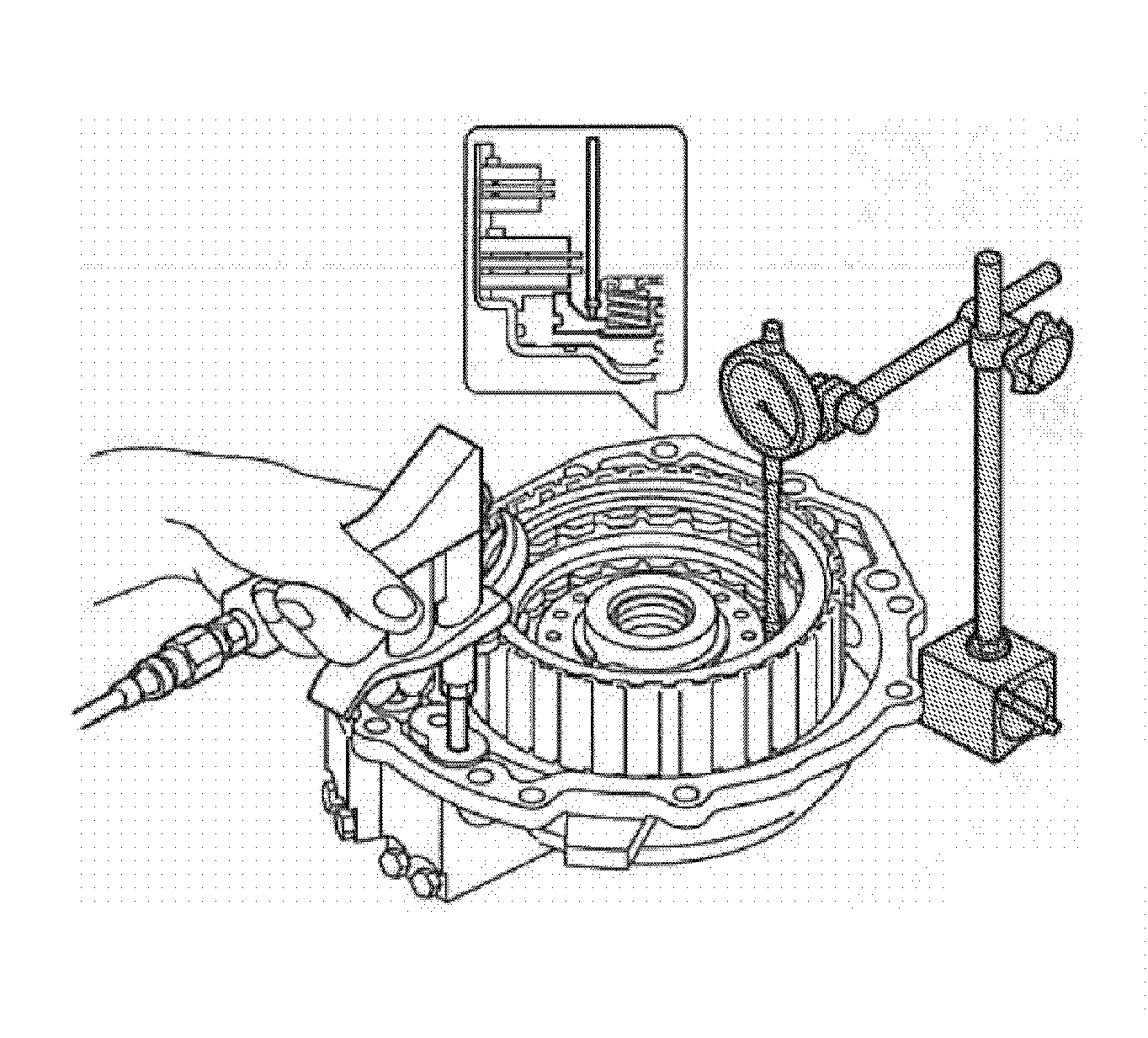
- Install the coast clutch assembly into the transmission rear cover, and set the
SA9179NE dial indicator
as shown.
- When applying and releasing compressed air 392 KPa (56 psi) into the fluid passage as shown, measure the coast clutch piston stroke. Piston stroke
2.682-3.018 mm (0.105-0.120 in).
- If the piston stroke is out of standard, select another flange.
| • | Flange thickness type =
3.6 mm (0.14 in). |
| • | Flange thickness type =
3.8 mm (0.15 in). |
| • | Flange thickness type =
4.0 mm (0.16 in). |
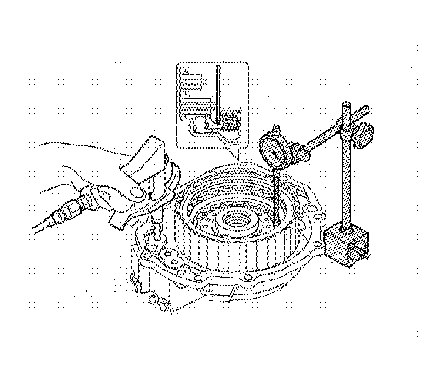
- Install the overdrive clutch assembly into the transmission rear cover, and set the
SA9179NE dial indicator
as shown.
- When applying and releasing compressed air 392 KPa (56 psi) into the fluid passage as shown, measure the overdrive clutch piston stroke.
| • | Piston stroke
0.762-1.038 mm (0.030-0.040 in). |
| • | Piston stroke
1.043-1.357 mm (0.041-0.053 in). |
- If the piston stroke is out of standard, select another flange.
| • | Flange thickness type =
3.6 mm (0.14 in). |
| • | Flange thickness type =
3.8 mm (0.15 in). |
| • | Flange thickness type =
4.0 mm (0.16 in). |


