Center Pillar Replacement Sedan
Removal Procedure
Warning: Refer to Approved Equipment for Collision Repair Warning in the Preface section.
Note: Section in specified area only. Sectioning outside of these areas may compromise the structural integrity of the vehicle. The sectioning procedures have been developed as a more cost-effective alternative to complete panel replacement.
- Disable the supplemental inflatable restraint (SIR) system.
- Disconnect the negative battery cable.
- Remove all related panels and components.
- Repair as much of the damage as possible to factory specifications. Refer to Dimensions - Body.
- Note the location and remove the sealers and anti-corrosion materials from the repair area as necessary. Refer to Anti-Corrosion Treatment and Repair.
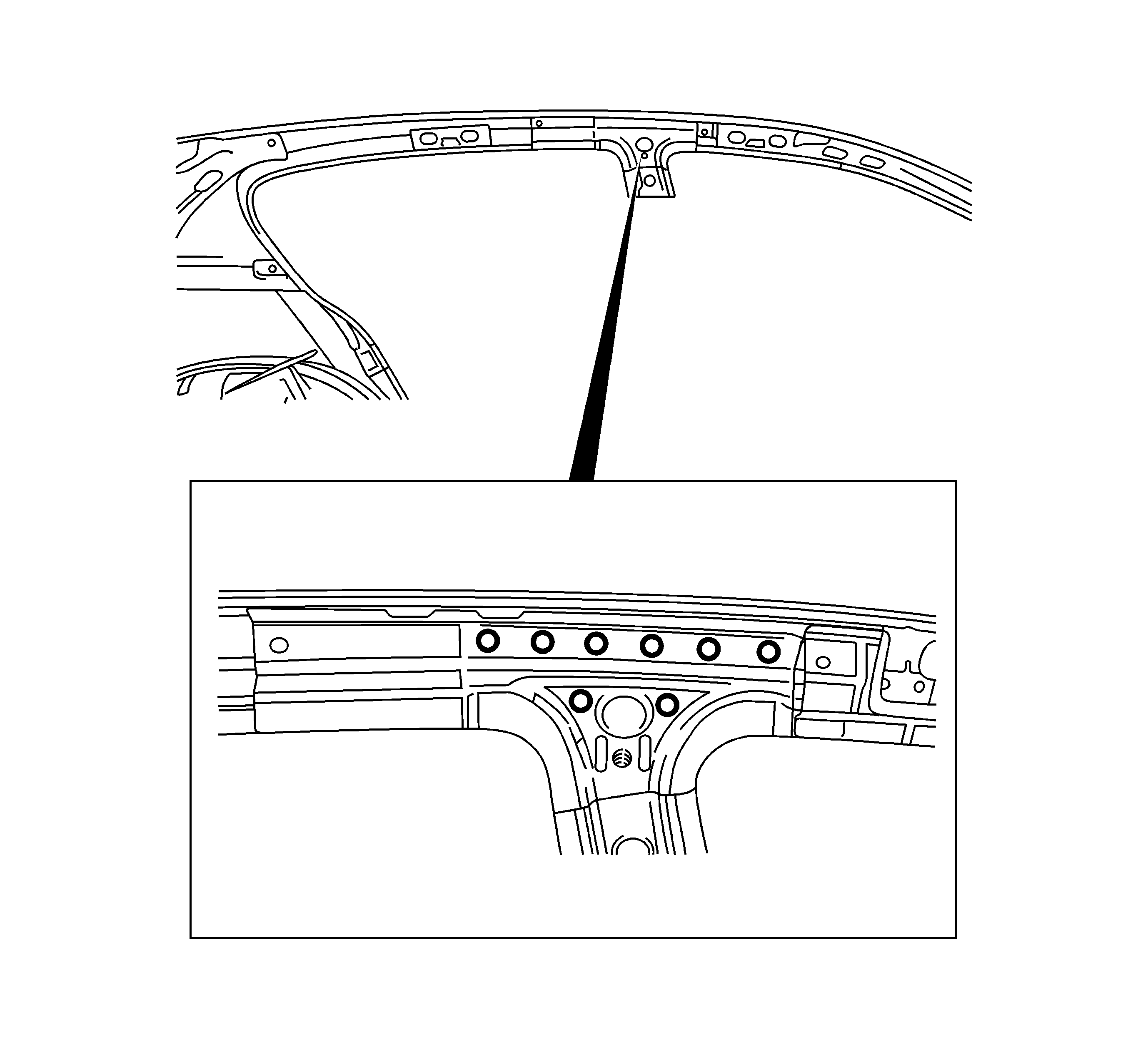
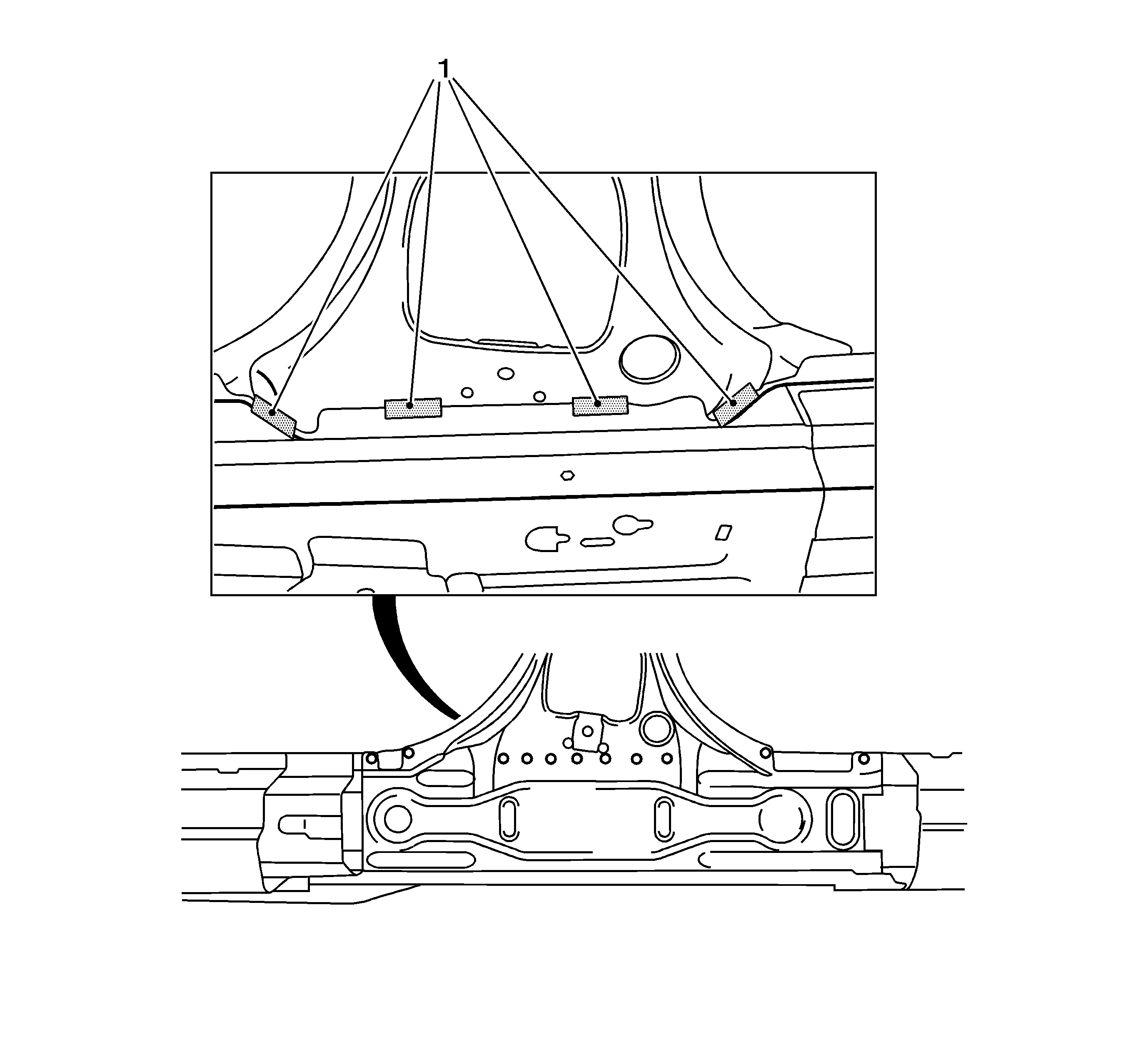
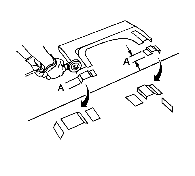
- Measure and mark sectioning lines as shown on the seal mounting strip.
- Locate and drill out factory spot welds securing seal mounting strip to body.
- Section the mounting strip and remove.
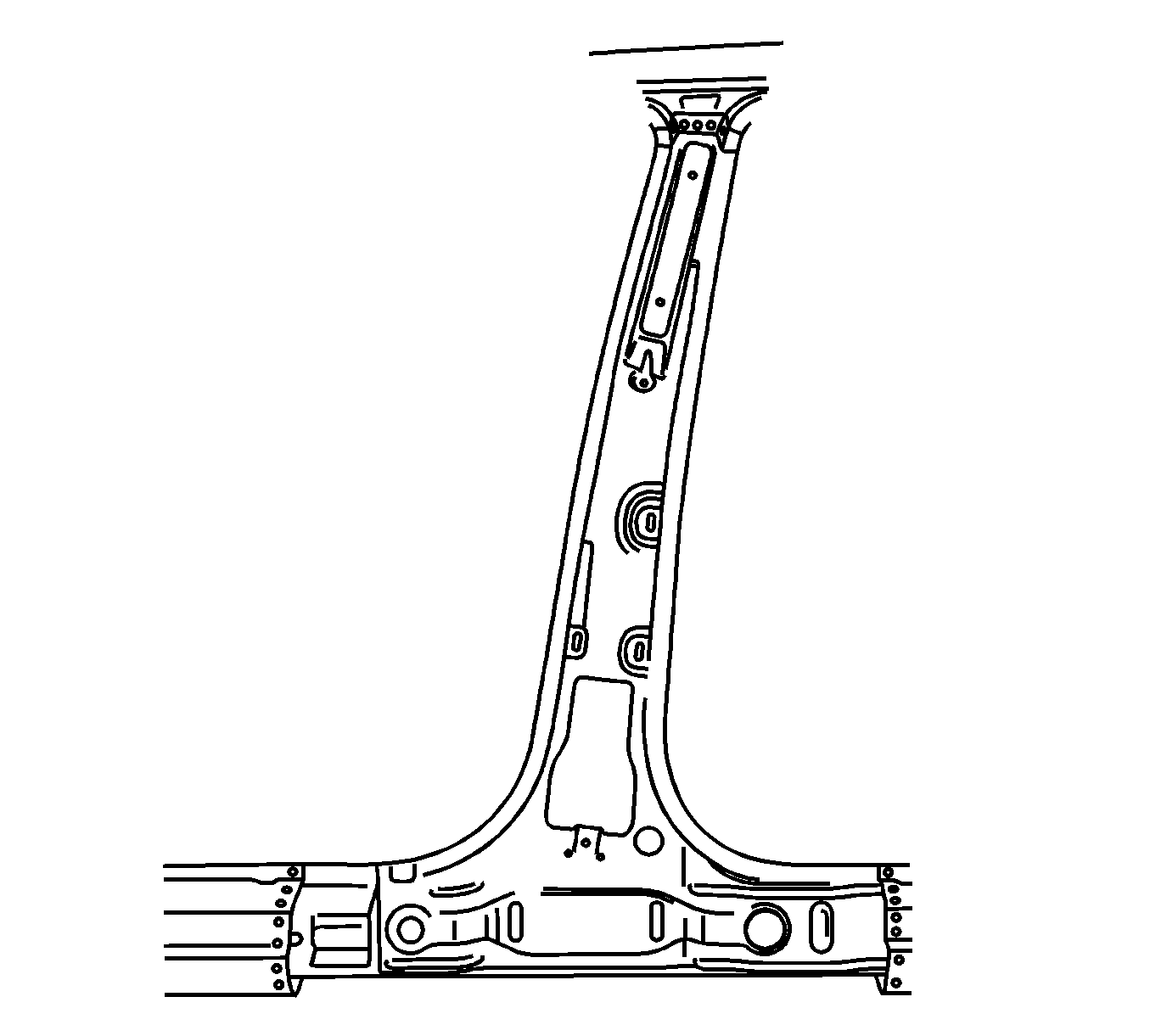
- Cut away B-pillar with inner reinforcement and inner pillar.
- Remove the damaged center pillar.
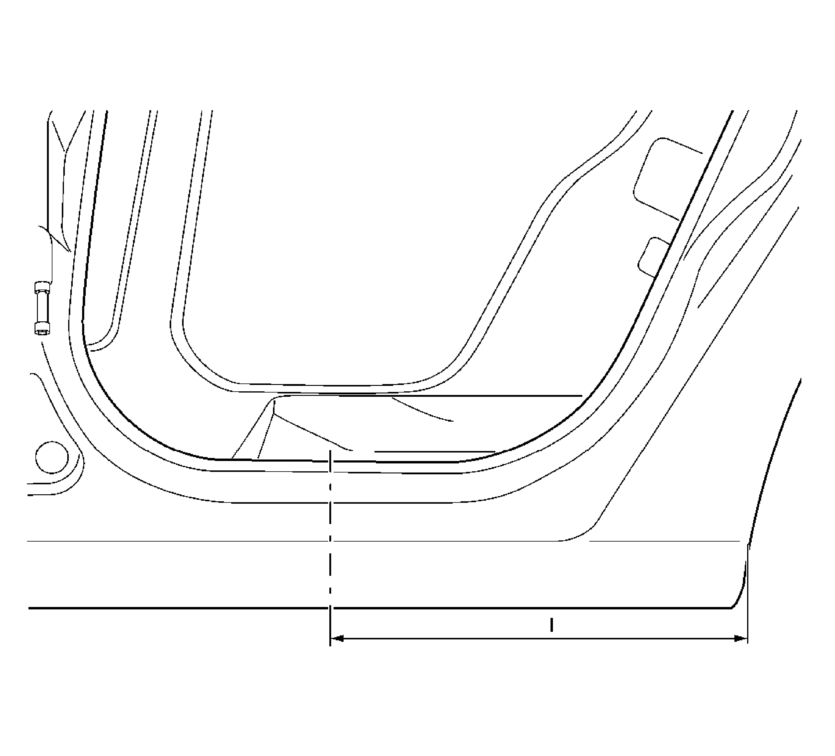
- Measure and mark vertical sectioning locations as shown. Location (I) = approximately 125 mm, location (II) = approximately 135 mm.
- Measure and mark horizontal sectioning location as shown. Location (-) approximately 15 mm from feature line.
- Cut away exterior of B-pillar at the top.
- Locate and drill out factory spot welds at the top with the inner reinforcement.
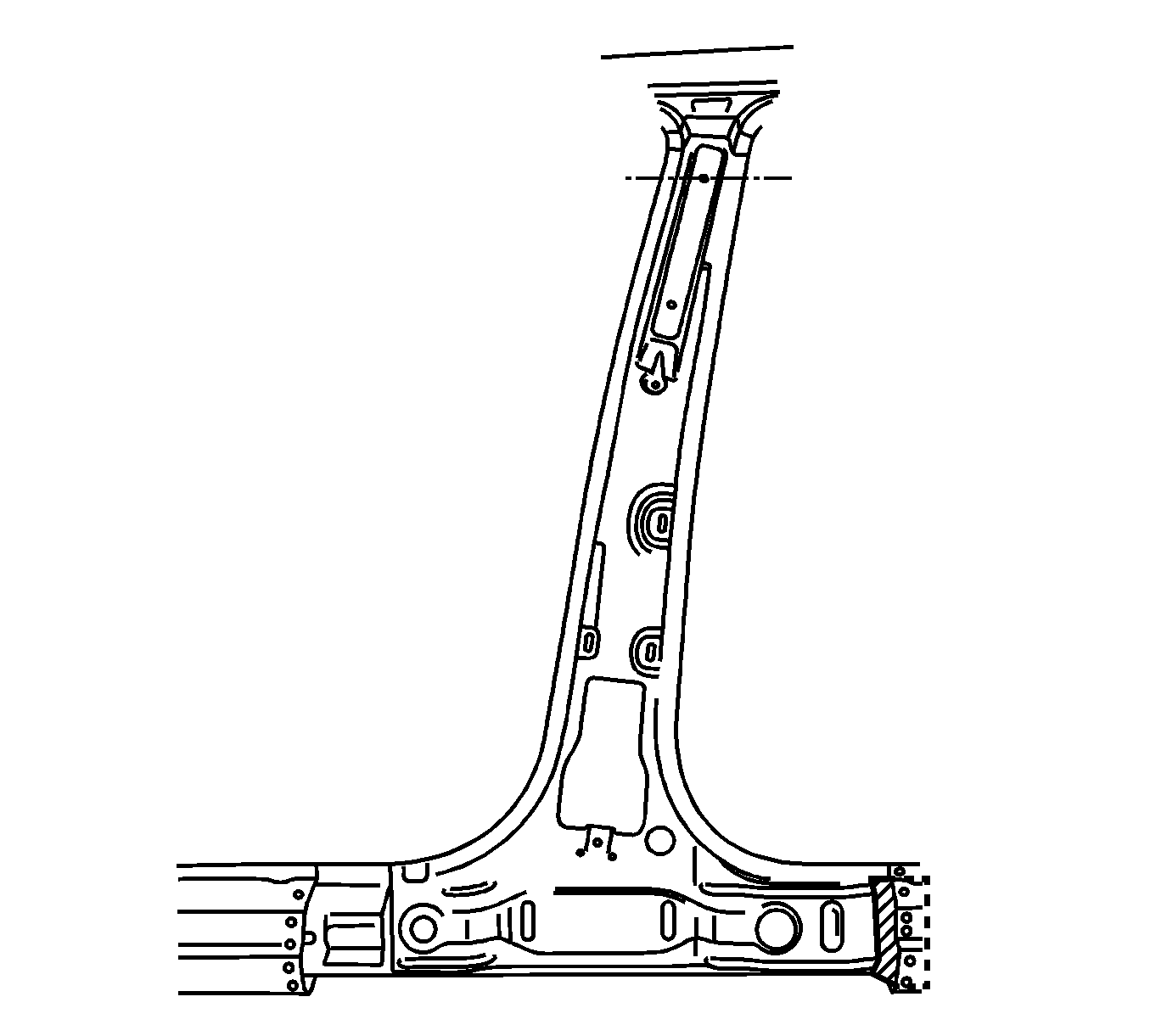
- Measure and mark sectioning lines as noted (I) approximately 380 mm.
- Cut B-pillar on the inside at the top.
- Measure and mark sectioning line as noted (I) approximately 20 mm.
- Cut B-pillar on the inside at the top.
- Locate and drill out welds at the top of the B-pillar.
- With a suitable tool, fold B-pillar downward.
- Locate and drill out welds to separate B-pillar reinforcement from the roof frame reinforcement at the top.
- Prepare front mating surface of B-pillar on the inside at the top. Mark sectioning line (I) approximately 20 mm.
- Bend down tab (1).
- Prepare rear mating surface of B-pillar on the inside at the top. Mark sectioning line (I) approximately 20 mm.
- Bend down tab (1).
- Measure and mark vertical lines on the rocker panel as shown.
- Cut the panel when indicated.
- Locate and drill out factory welds in area of window.
- Remove the rocker panel window section.
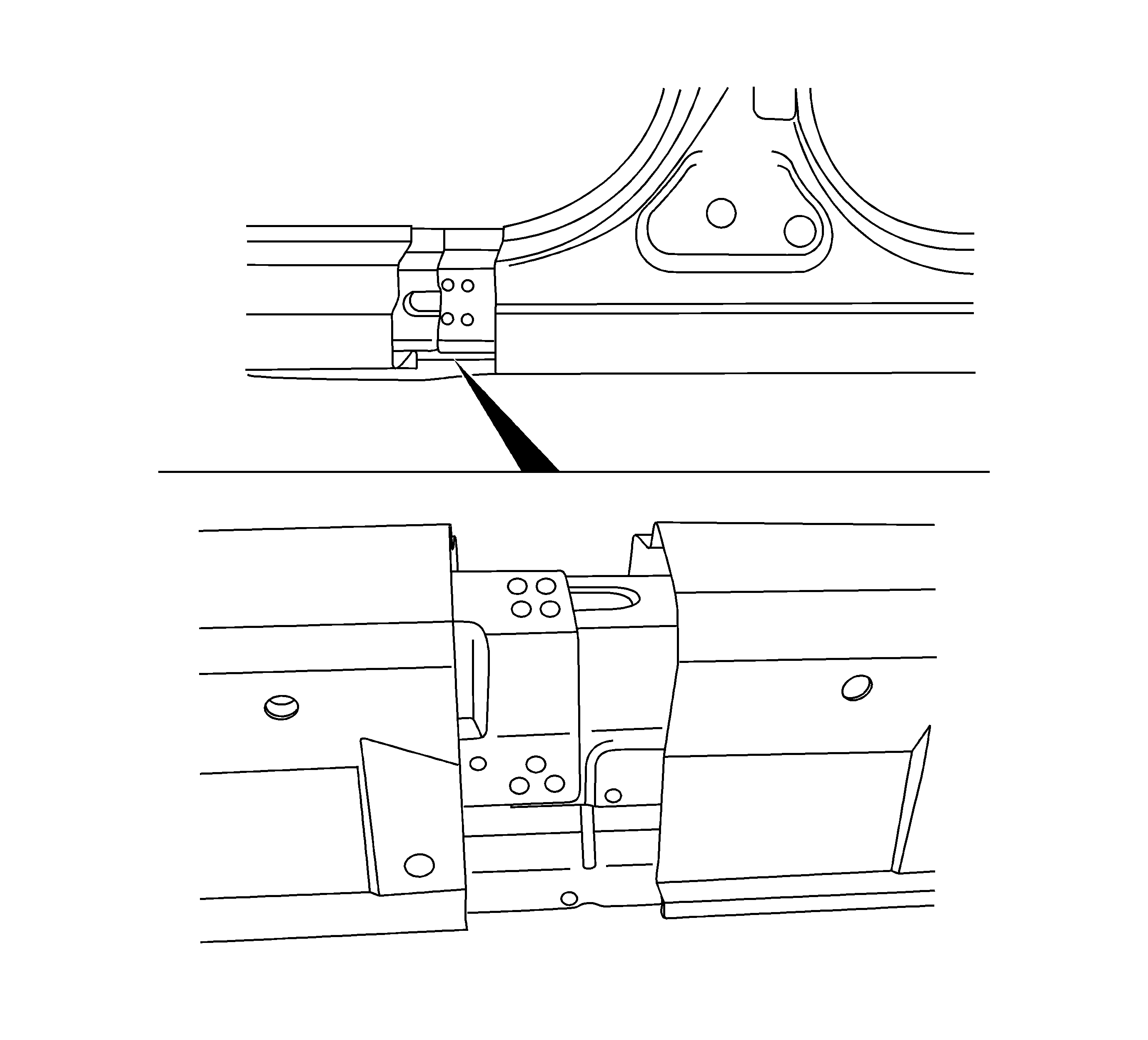
- Measure and mark a vertical line as shown. Sectioning cut (1) is approximately 430 mm from wheel opening flange.
- Locate and drill out factory welds at the front of the center pillar reinforcement.
- Locate and drill out welds securing the B-pillar with inner reinforcement from the door cut-out and rear.
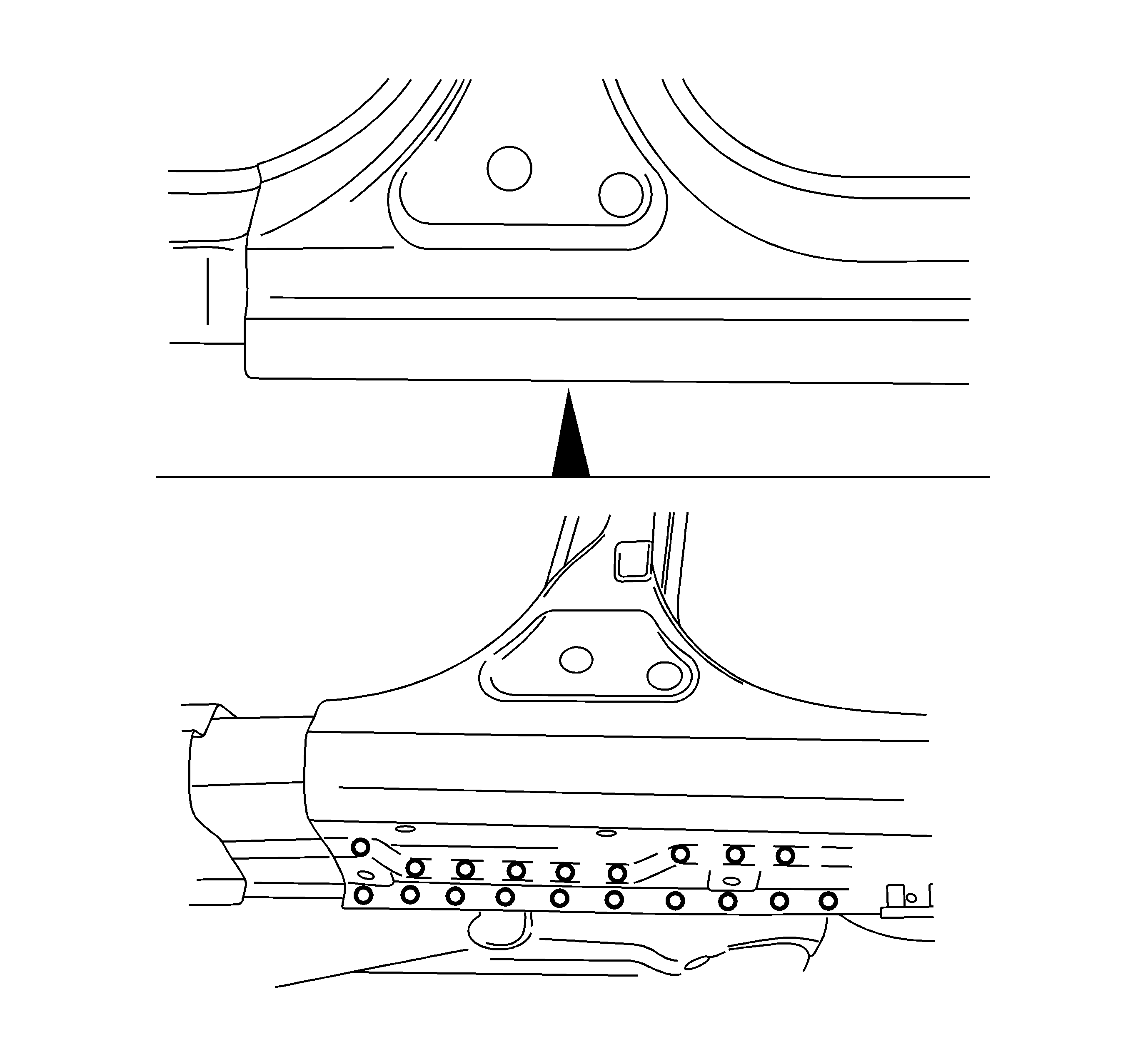
- Locate and drill out factory welds securing lower B-pillar with interior reinforcement from the body.
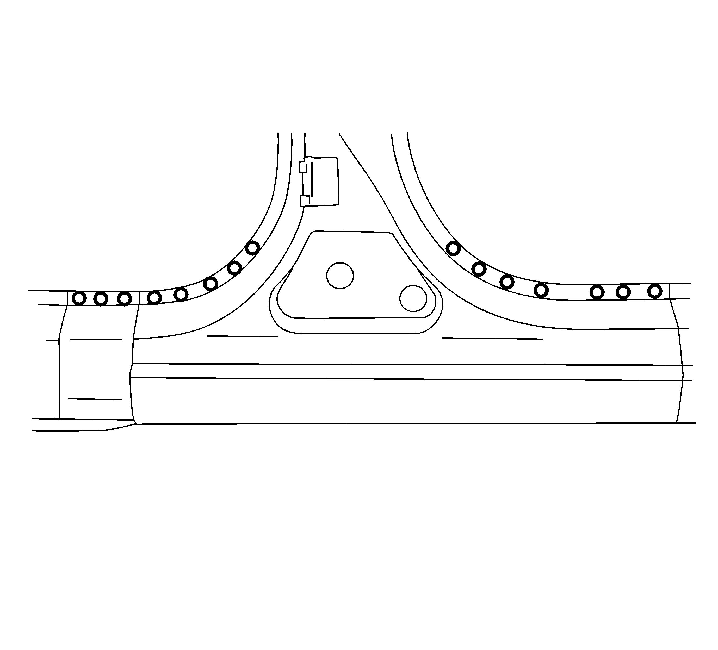
- Locate and drill out welds on the inside of the B-pillar as shown.
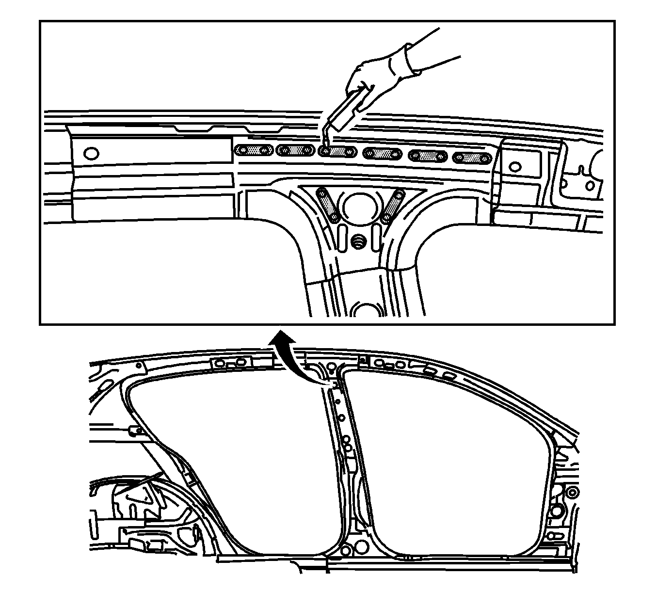
- Grind off MIG-brazed seams (1) in locations shown.
- Prepare B-pillar lower for new part installation. Measure and mark section line (I) 20 mm.
- Remove damaged center pillar from the vehicle.
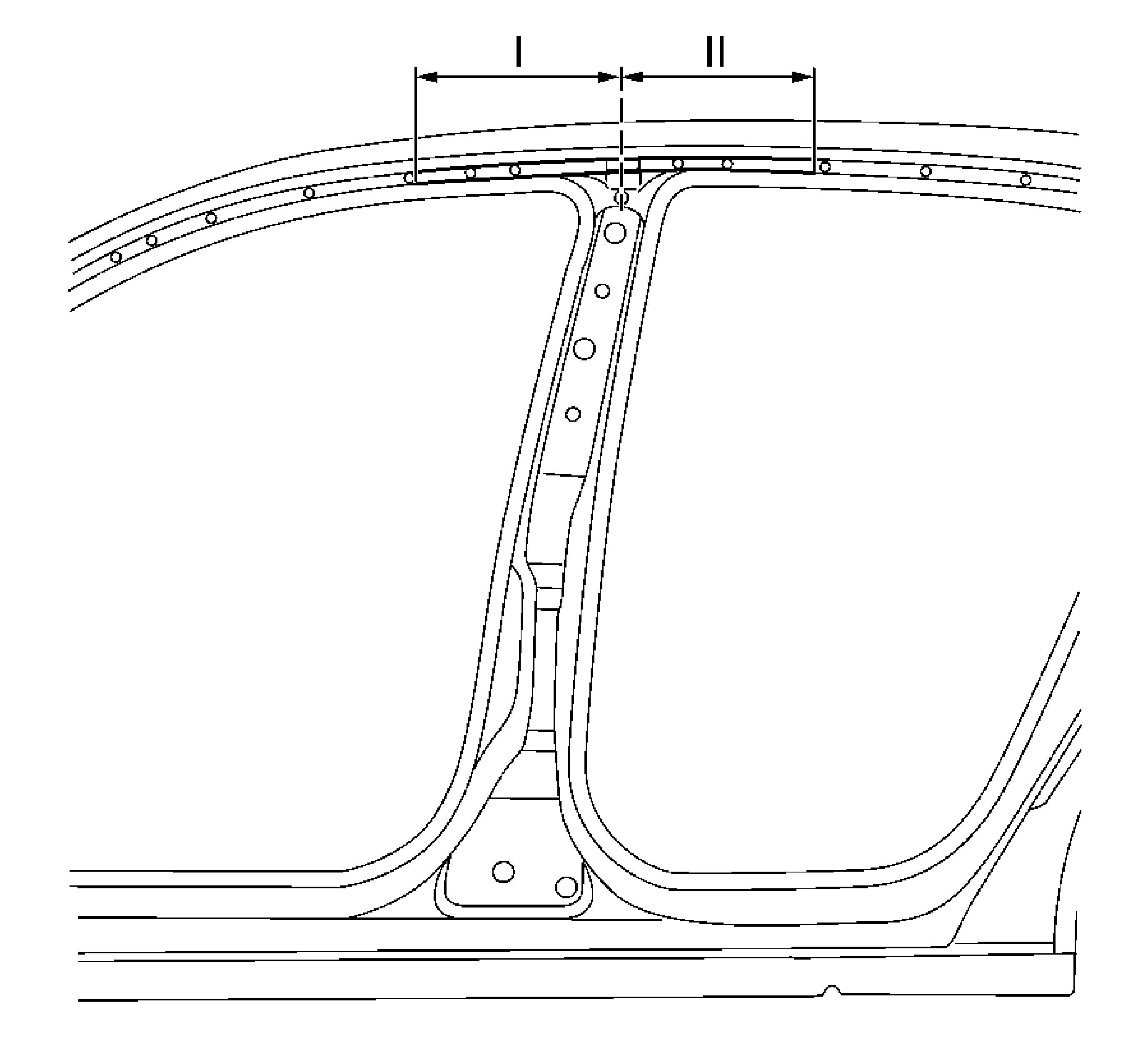
Note: Both lines (I and II) are approximately 300 mm from center of locating hole.
Note: Set part aside to be reused unless a new mounting strip is needed.
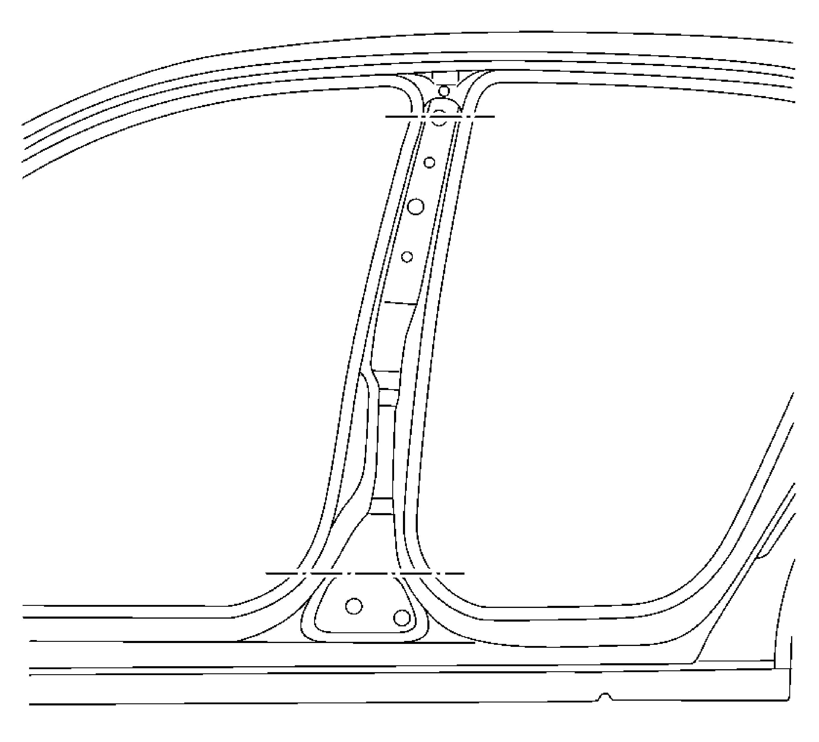
Note: Note size of new part. Place top sectioning cut centrally through the upper mounting hole for the belt height adjustment.
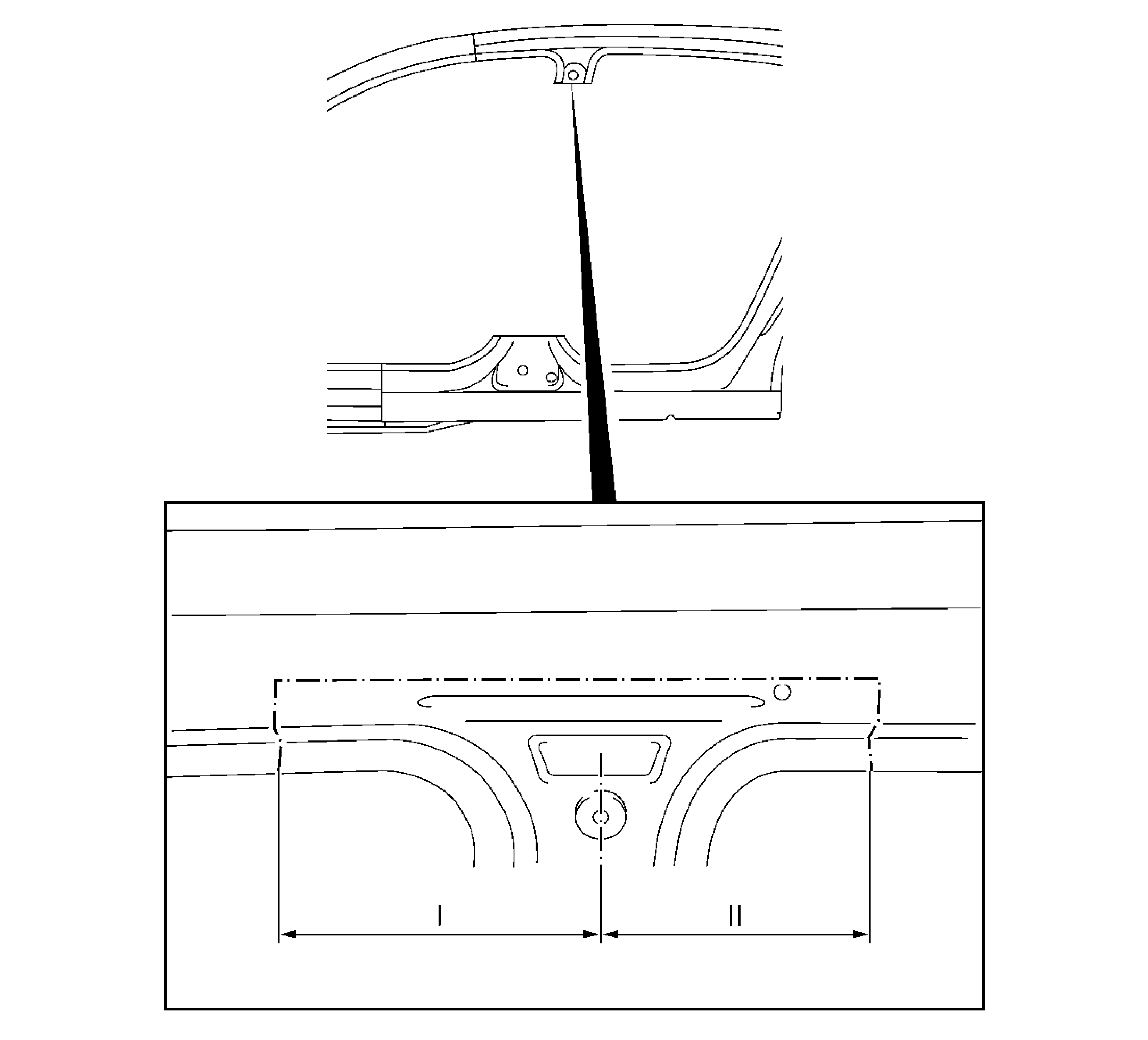
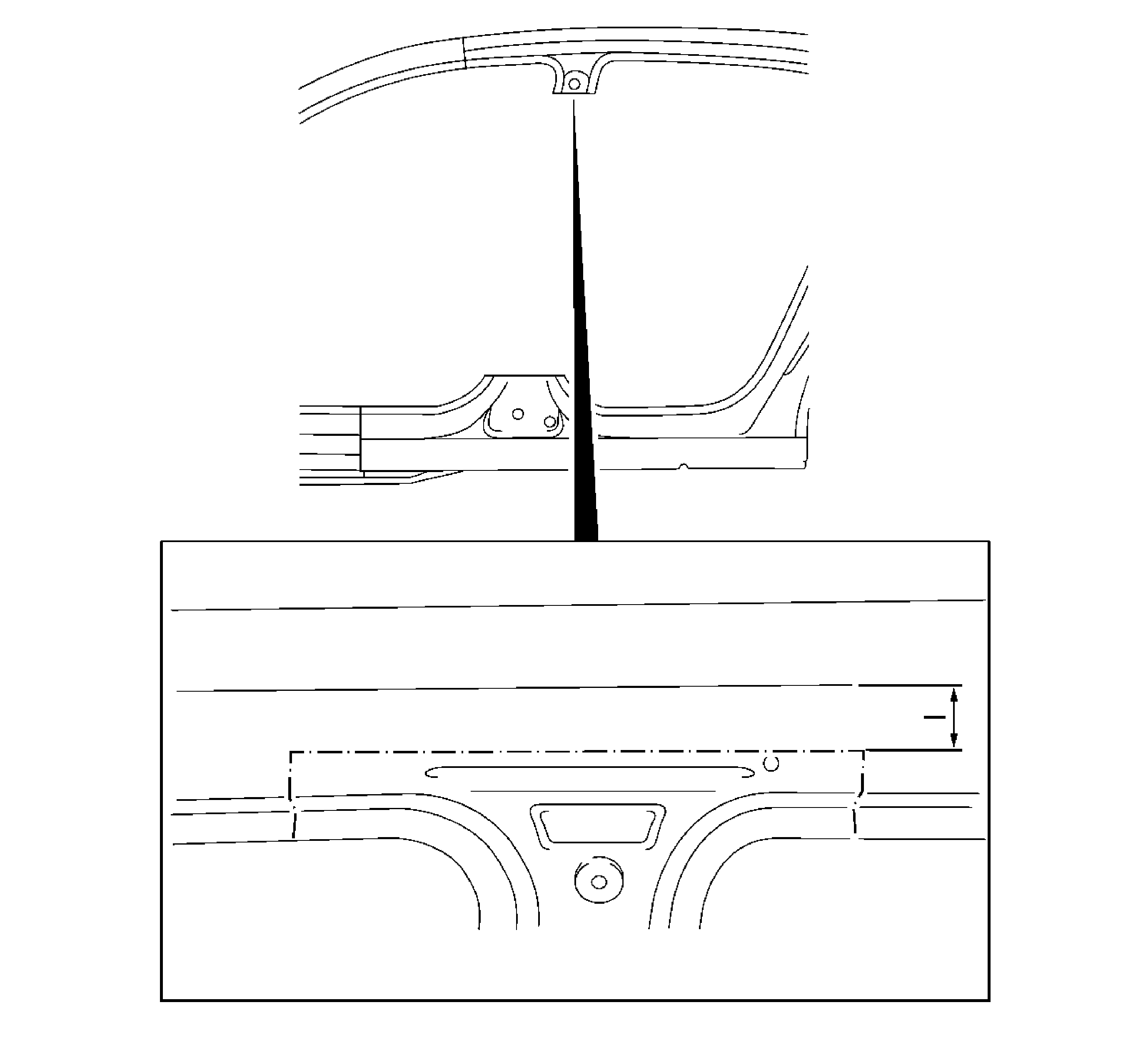
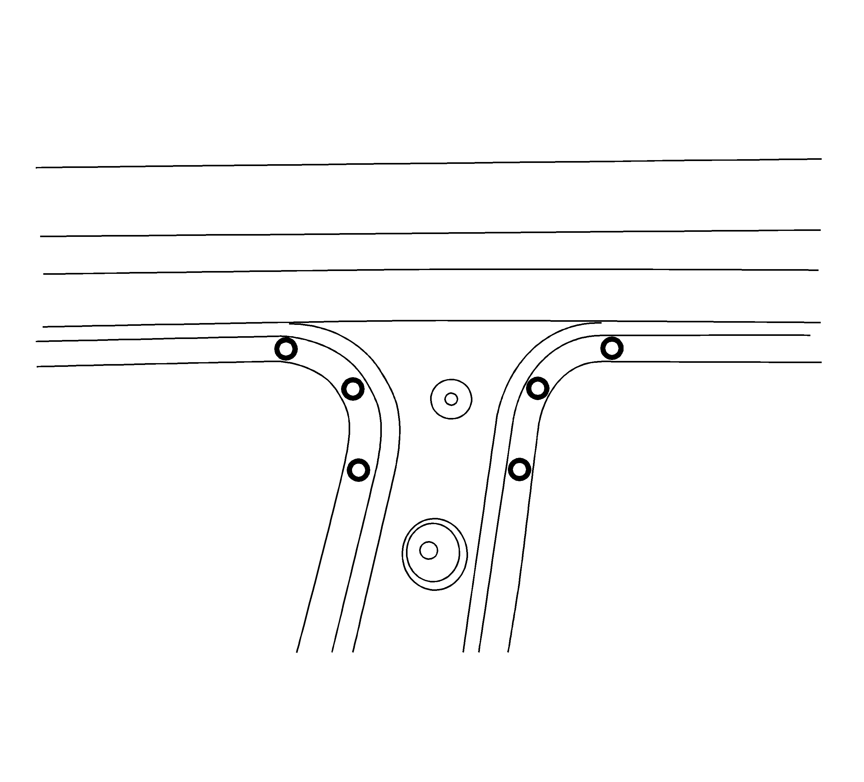
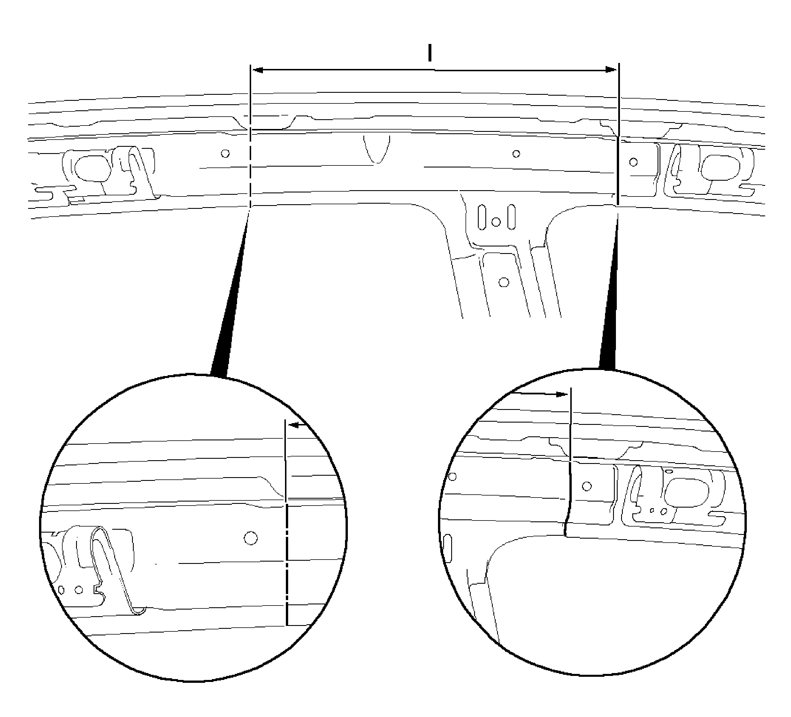
Note: Note size of the new replacement part.
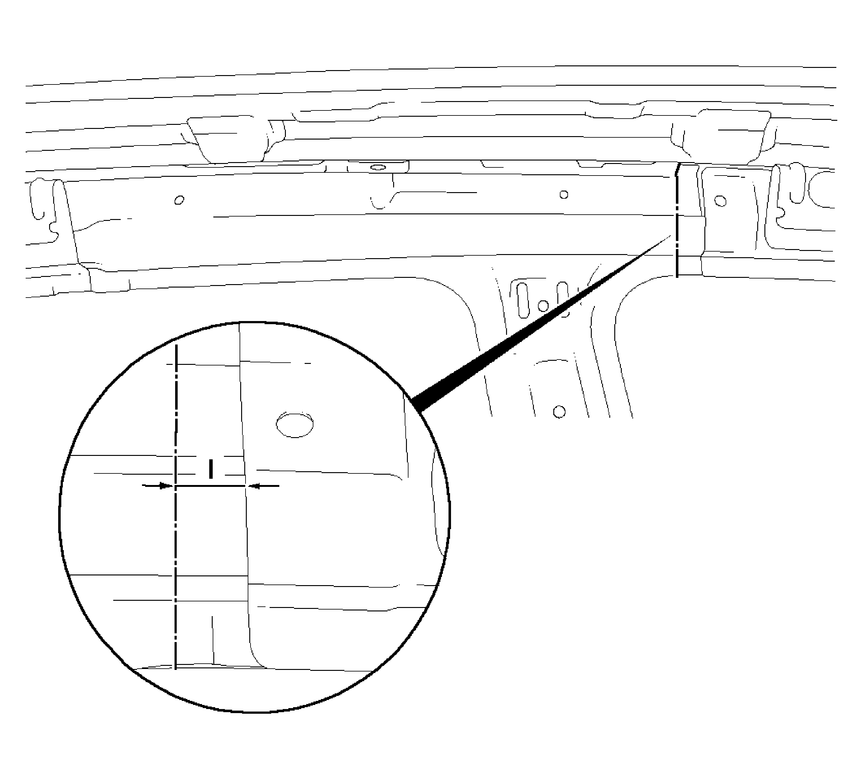
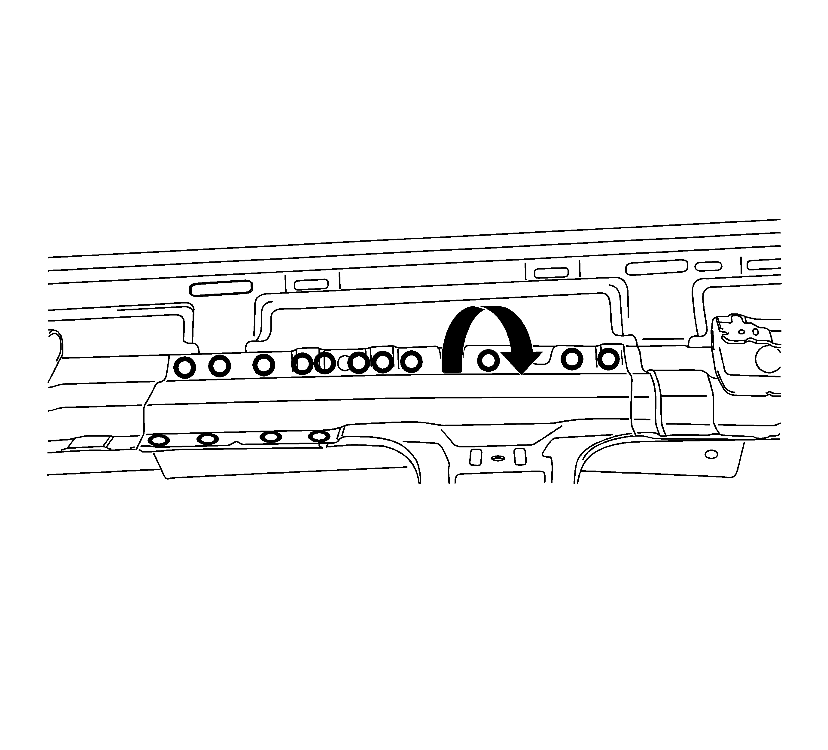
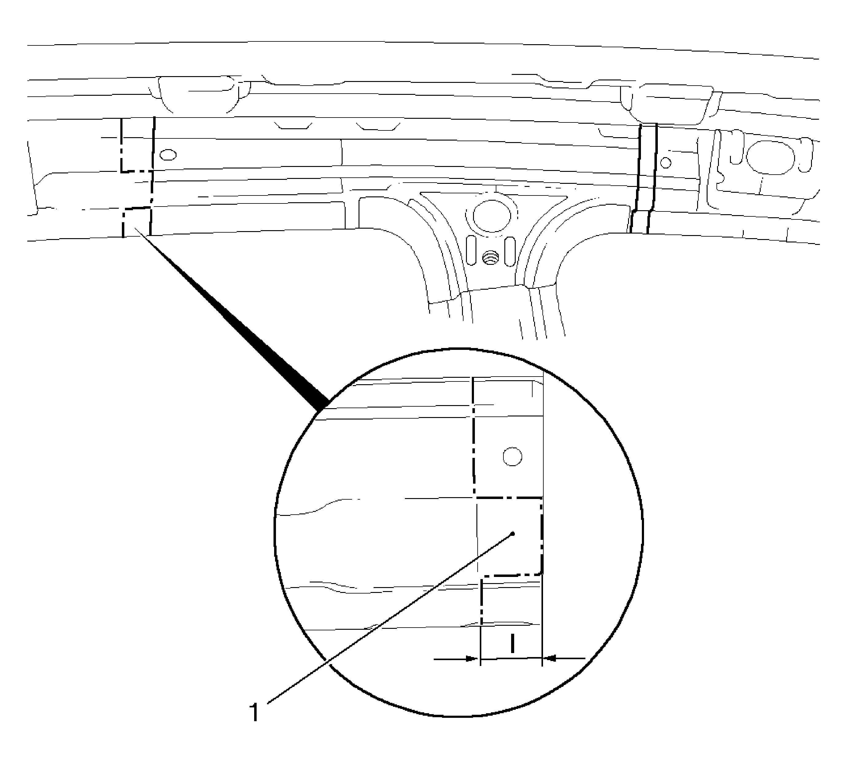
Note: Note size of new replacement part.
Note: Inner B-pillar new replacement part will be placed over tab later.
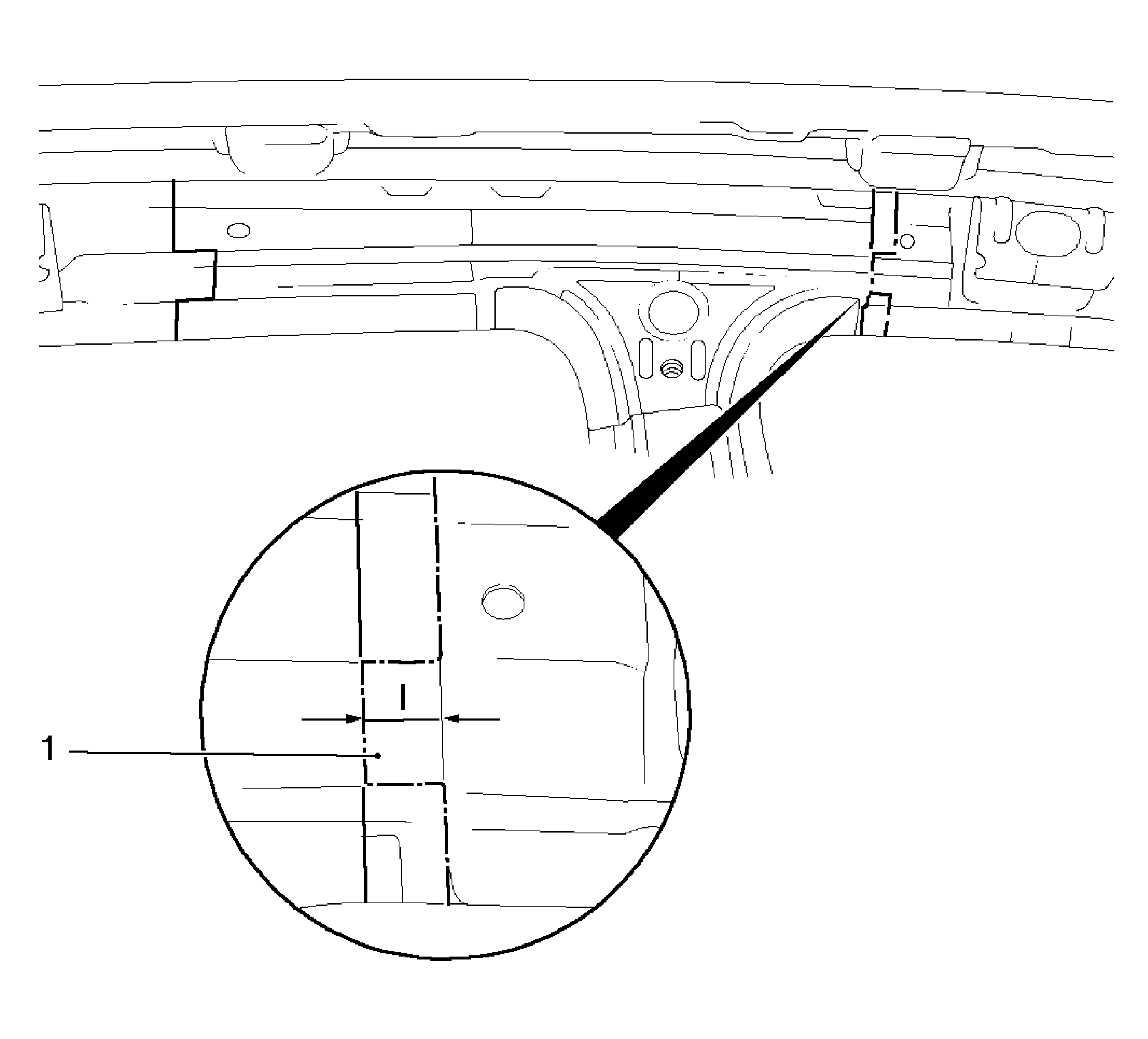
Note: Inner B-pillar new replacement part will be placed over tab later.
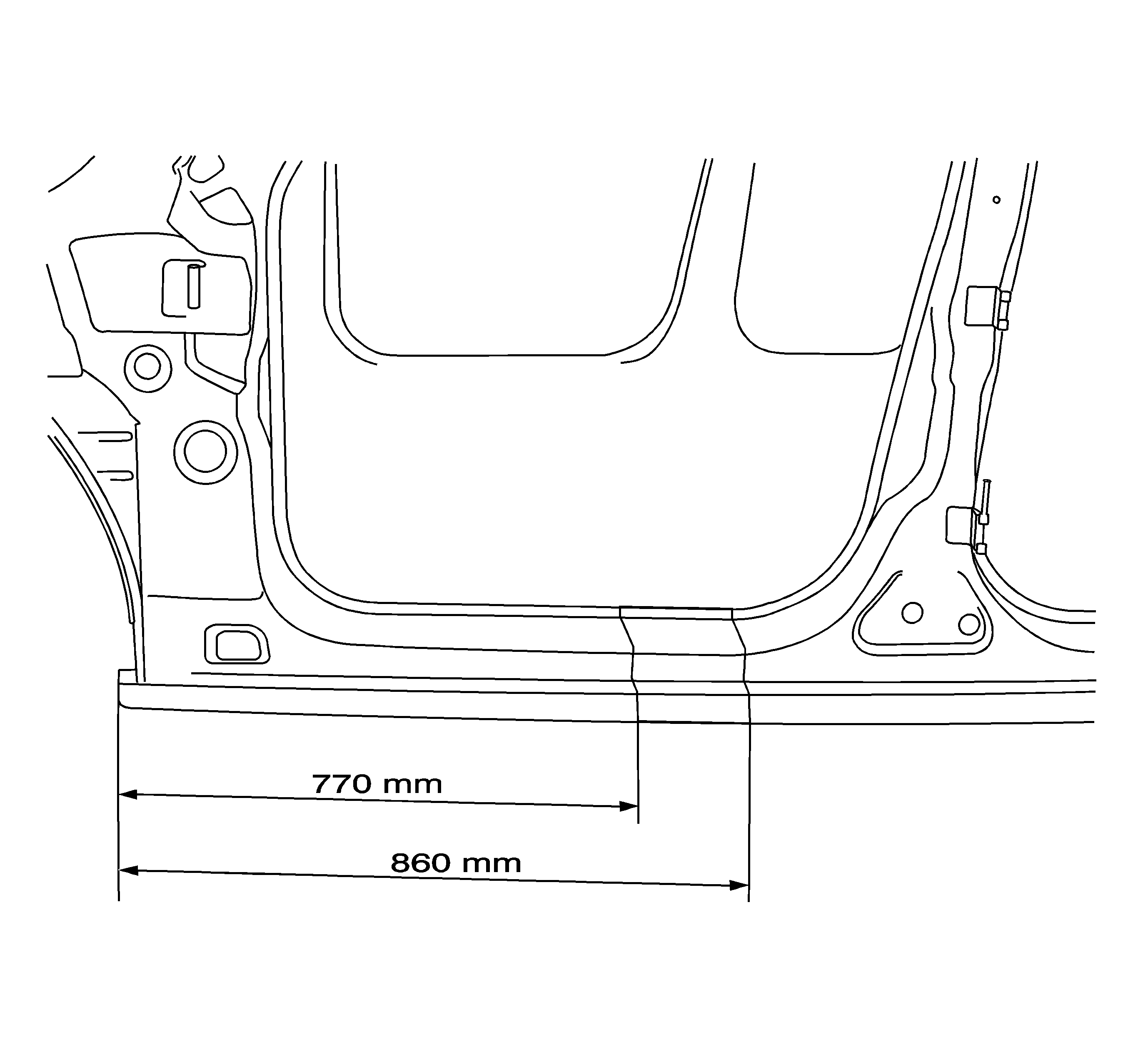
Note: A window must be cut in the rocker outer panel to gain access to the center pillar reinforcement welds. Note size of new part. Do not damage any inner panels or reinforcements.
Installation Procedure
- On the service replacement part, cut extension at joint as shown.
- On the service replacement part at the top of the B-pillar inner, cut joints to size so they are flush.
- On the lower inner B-pillar, cut joint to size so that it is flush.
- Remove new part, B-pillar, on the inside.
- Drill 8 mm (5/16 in) plug weld holes in the replacement part as necessary in locations noted from the original panel.
- Position the replacement B-pillar inner to the vehicle using 3-dimensional measuring equipment. Clamp in place.
- Weld in B-pillar on the inside at the bottom.
- Measure and mark vertical sectioning locations on the exterior of B-pillar at the top of the new replacement part. Mark (I) is approximately 145 mm, mark (II) is approximately 155 mm from center line of hole.
- Measure and mark horizontal sectioning location on the exterior of the B-pillar at the top of the new replacement part. Mark (-) is approximately 5 mm.
- Cut away exterior panel at sectioning locations.
- On the new replacement service part, locate and drill out inner B-pillar at the top.
- Drill 8 mm (5/16 in) plug weld holes in the replacement part B-pillar inner as necessary in locations noted from the original panel.
- Measure and mark sectioning joint on the rocker outer panel as noted from the original sectioning location.
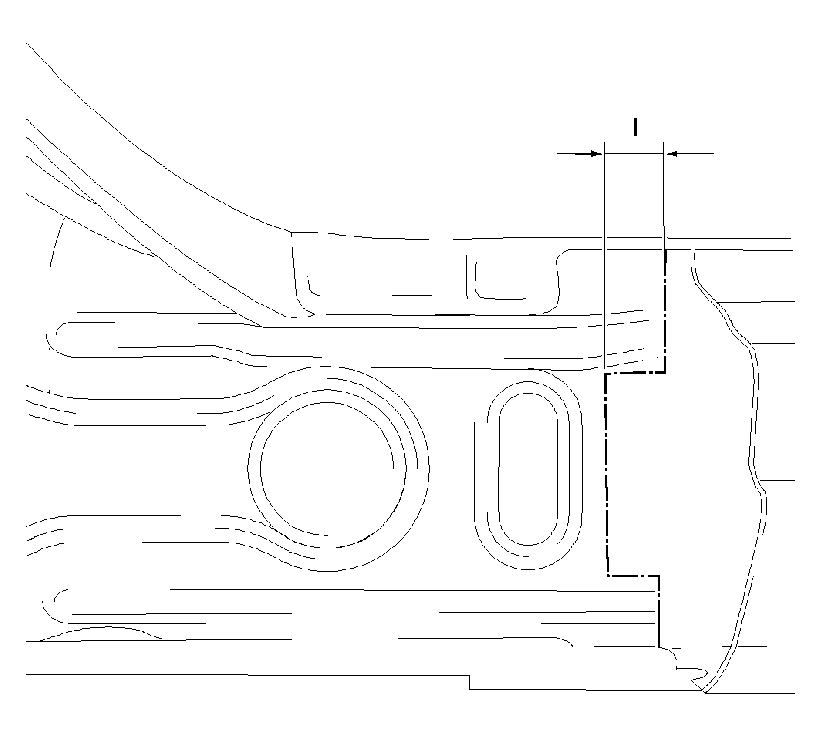
- Measure and mark a vertical line on the service part rocker panel as shown. The measurement (I) will be approximately 120 mm from edge of part.
- Drill 8 mm (5/16 in) plug weld holes in the replacement part as necessary in locations noted from the original panel.
- Create a 50 mm (2 in) backing plate from the unused portion of the replacement part or from same gauge scrap panels. Trim the backing plate as necessary to fit behind the sectioning joint where there are no reinforcements.
- Drill 8 mm (5/16 in) plug weld holes along the sectioning joint on the original panel. Locate these holes 13 mm (½ in) from the edge and spaced 40 mm (1½ in) apart.
- Prepare all mating surfaces as necessary.
- Apply GM approved Weld-Thru coating or equivalent to all mating surfaces. Refer to Anti-Corrosion Treatment and Repair.
- Fit the backing plate halfway into the sectioning joint at the rear of the center pillar reinforcement. Clamp and weld in place.
- Position the replacement center pillar to the vehicle using 3-dimensional measuring equipment. Clamp in place.
- Plug weld accordingly.
- Stitch weld the sectioning joint at rear of center reinforcement.
- Fit the backing plates halfway into the remaining sectioning joints. Clamp and weld into place.
- Locate and position the rocker panel window.
- Clamp and plug weld accordingly.
- Stitch weld the sectioning joint.
- Stitch weld the sectioning joint on the upper outer B-pillar.
- Stitch weld the sectioning joint along the B-pillar at the top.
- Complete plug welds on the inner B-pillar at the top.
- Position door frame sealing strip and secure with suitable tool.
- Plug weld accordingly.
- Prepare all welded surfaces as necessary.
- Apply the sealer and anti-corrosive materials to the repair area as necessary. Refer to Anti-Corrosion Treatment and Repair.
- Paint the repair area. Refer to Basecoat/Clearcoat Paint Systems.
- Install all the related panels and components.
- Connect the negative battery cable.
- Enable the SIR system.
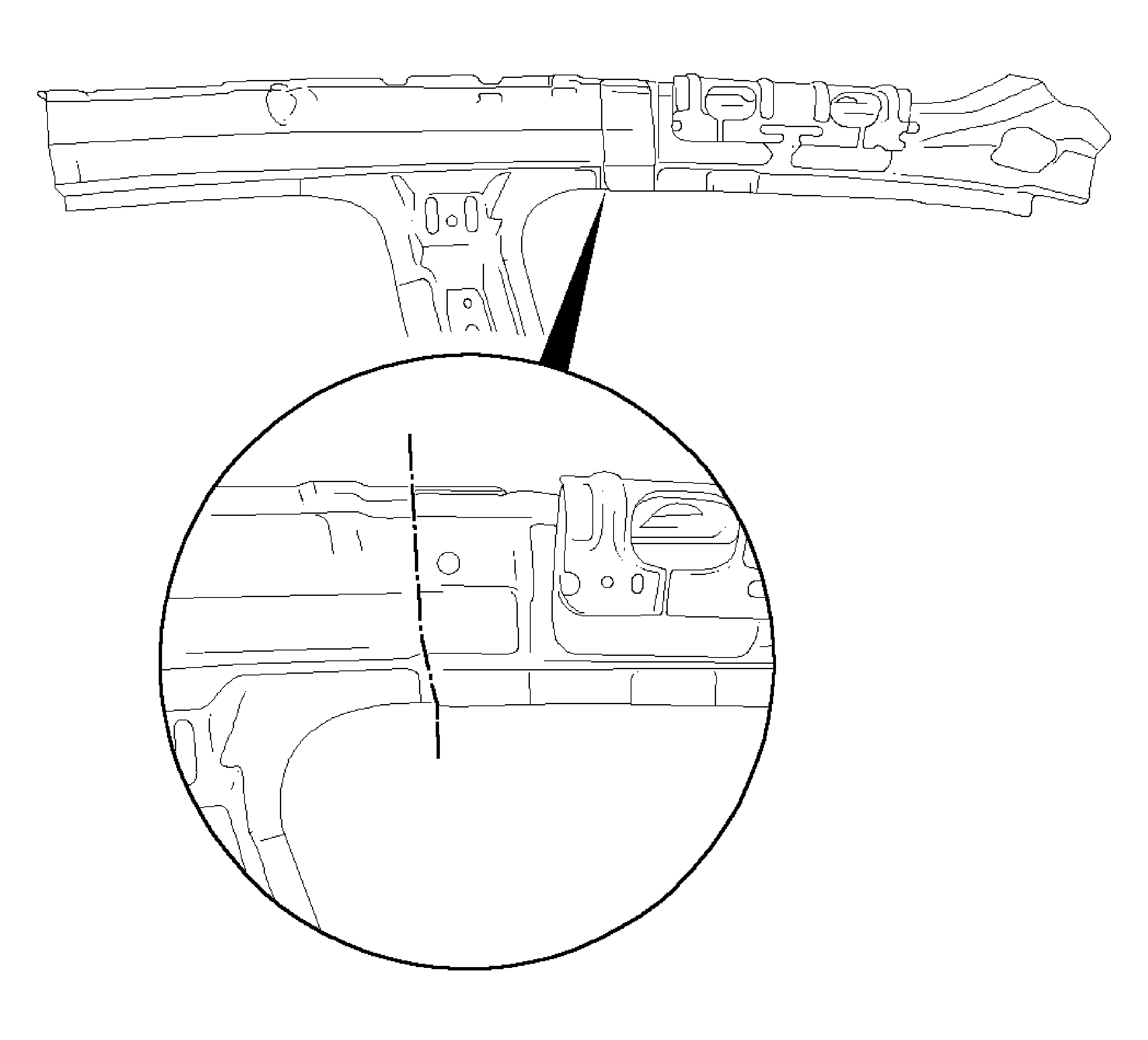
Note: Do not damage any inner panels or reinforcements.

Note: Both tabs (1) must be pushed under the new part.
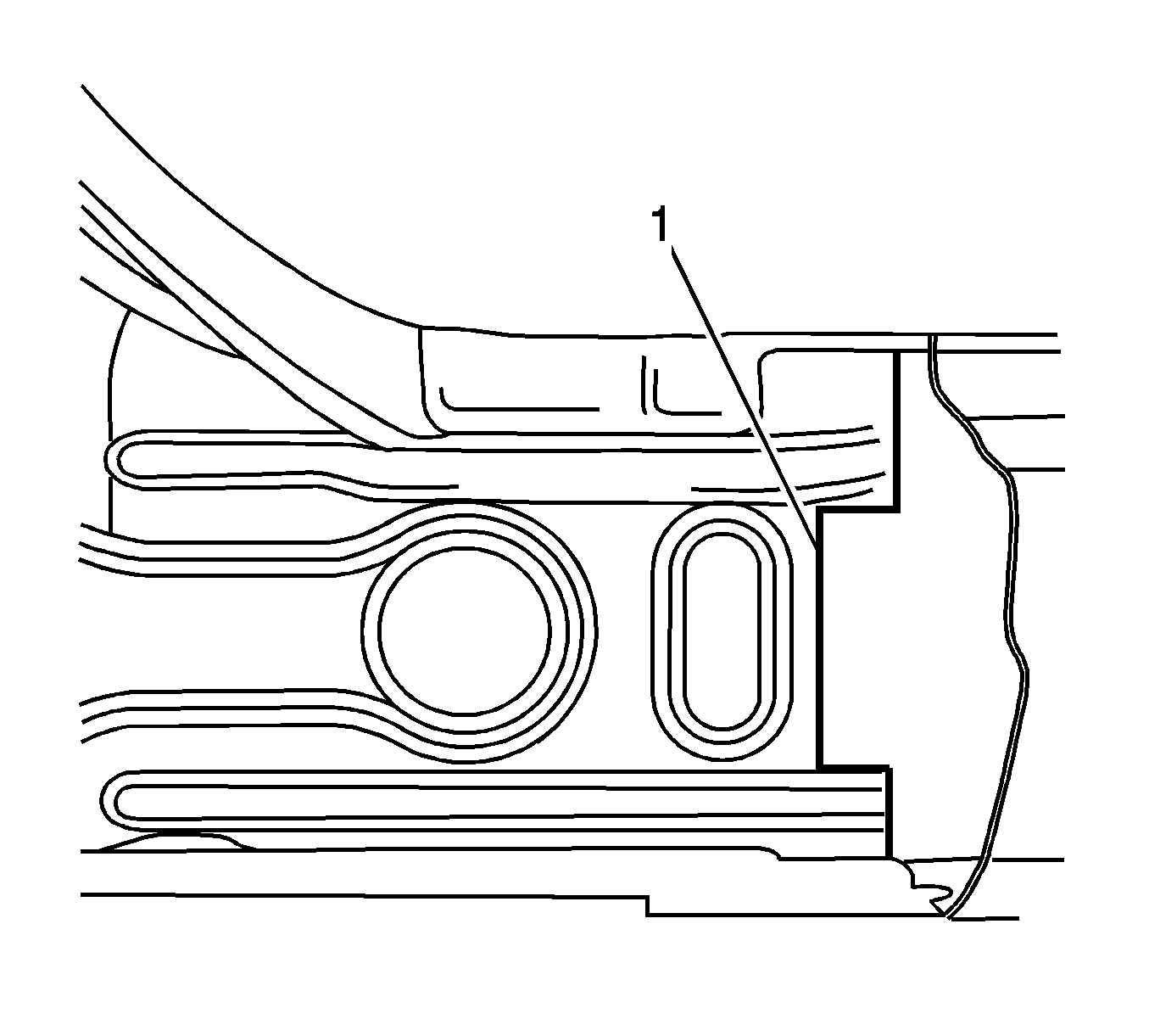
Note: Tab (1) must be pushed over new part.
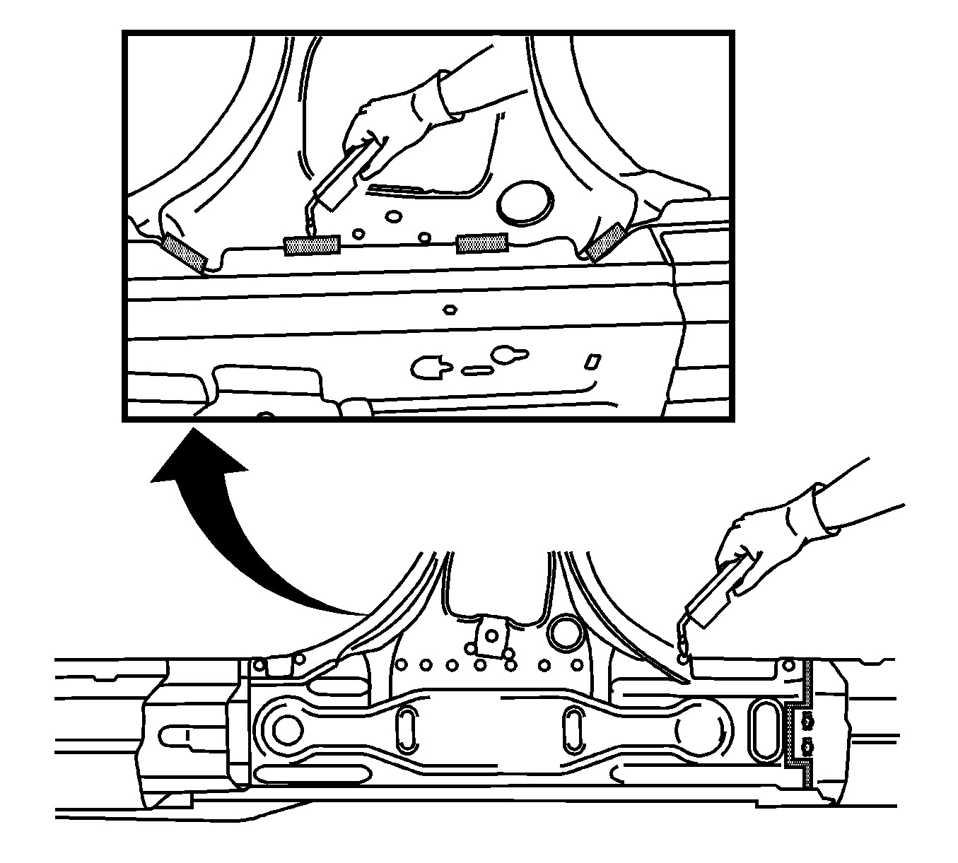
Note: B-pillar, inside top, is not welded until the joint has been made on the outside of the B-pillar.


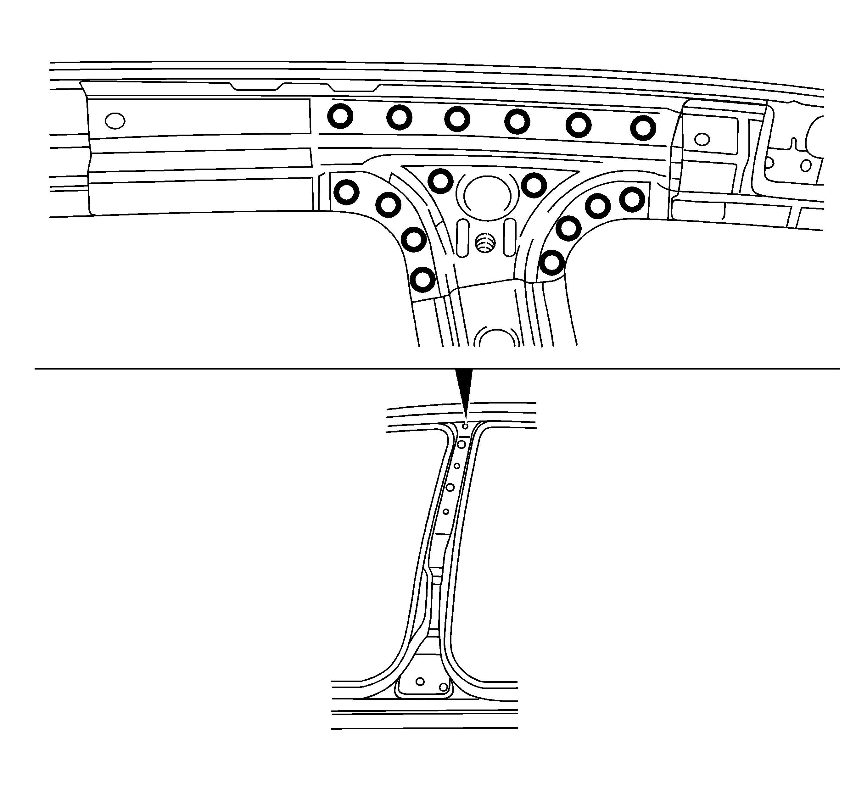
Note: Locate and drill out B-pillar reinforcement from the roof frame reinforcement on the inside.
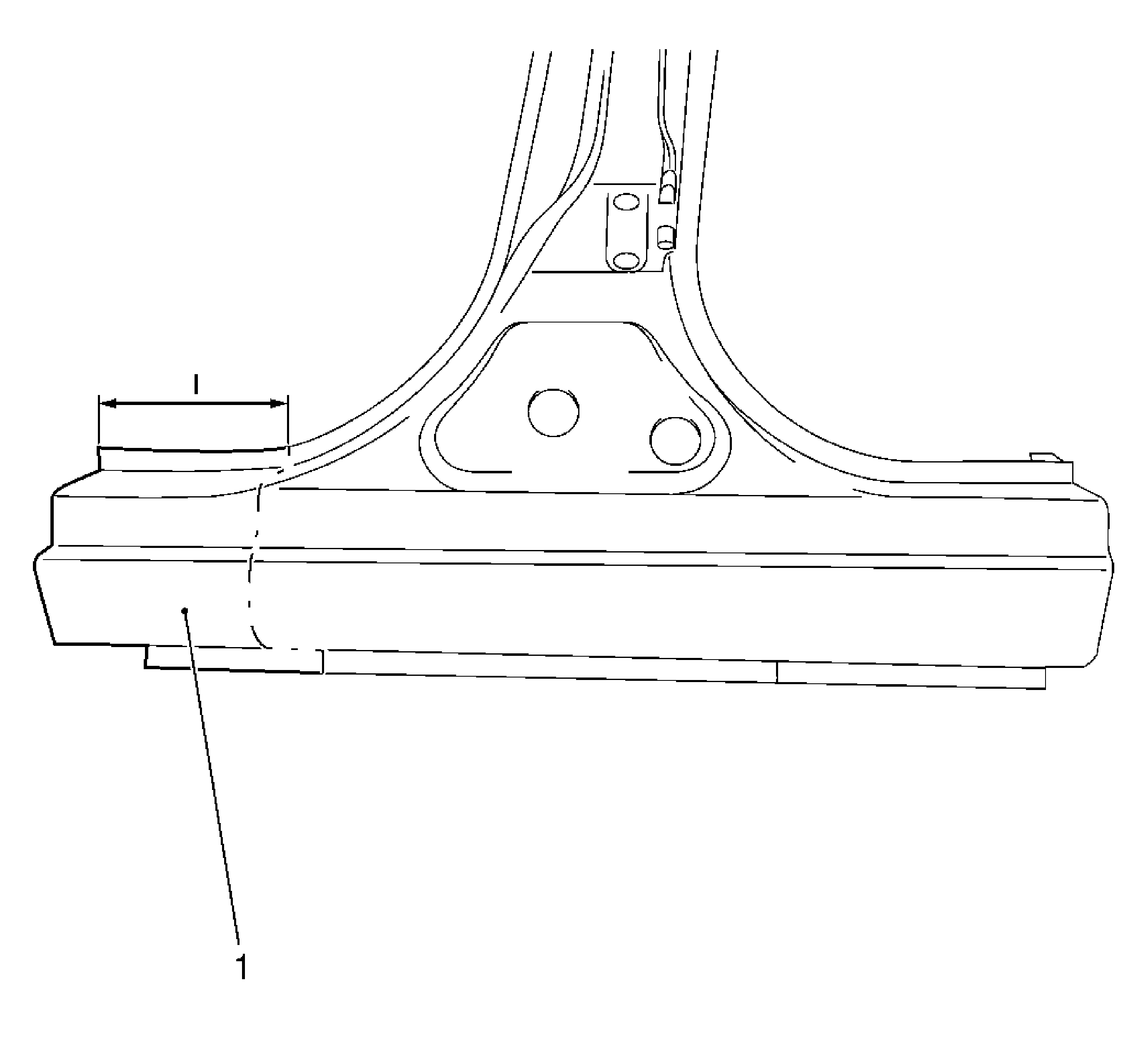
Note: Joint on front rocker panel is not cut to size until after the assembly window has been adjusted to fit. The assembly window (1) must be re-used.
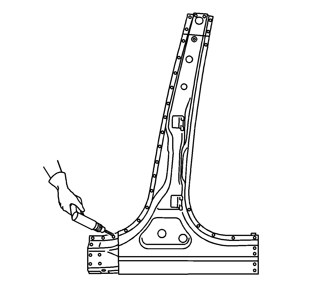
Note: If the location of the original plug weld holes cannot be determined, space the plug weld holes every 40 mm (1½ in) apart.
Note: To create a solid weld with minimum heat distortion, make 25 mm (1 in) stitch welds along the seam with 25 mm (1 in) gaps between.
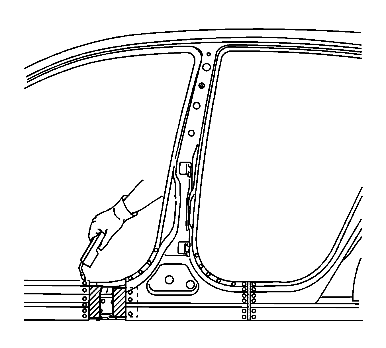
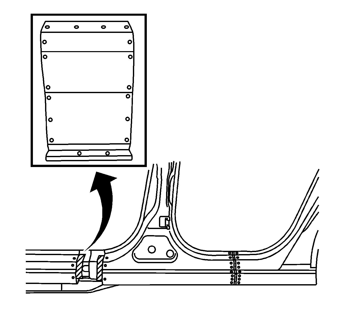
Note: To create a solid weld with minimum heat distortion, make 25 mm (1 in) stitch welds along the seam with 25 mm (1 in) gaps between.
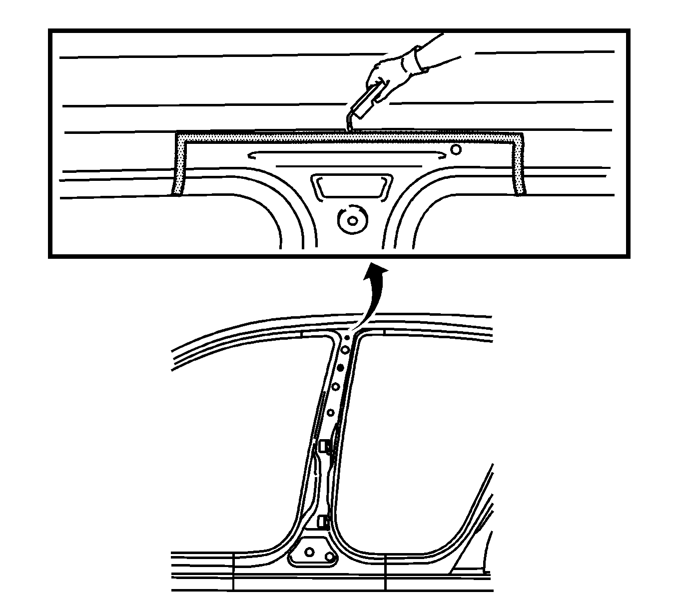
Note: Position inner upper B-pillar in the installation position before welding.
Note: To create a solid weld with minimum heat distortion, make 25 mm (1 in) stitch welds along the seam with 25 mm (1 in) gaps between.
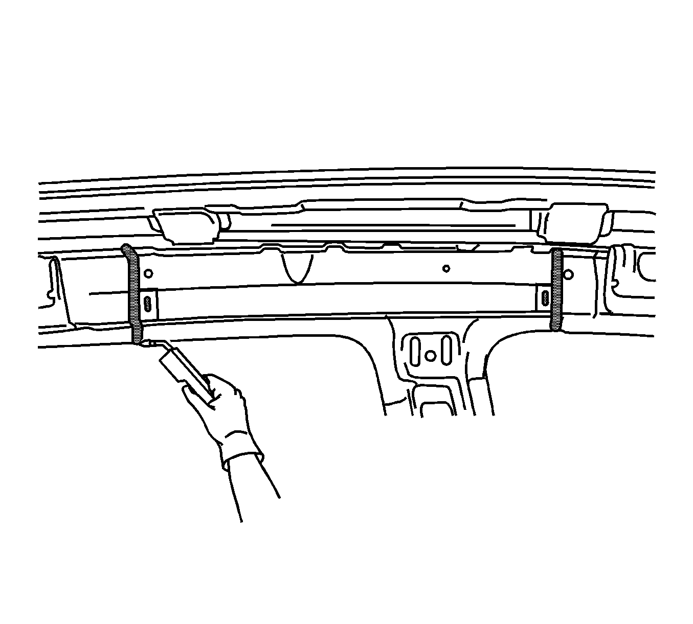
Note: To create a solid weld with minimum heat distortion, make 25 mm (1 in) stitch welds along the seam with 25 mm (1 in) gaps between.
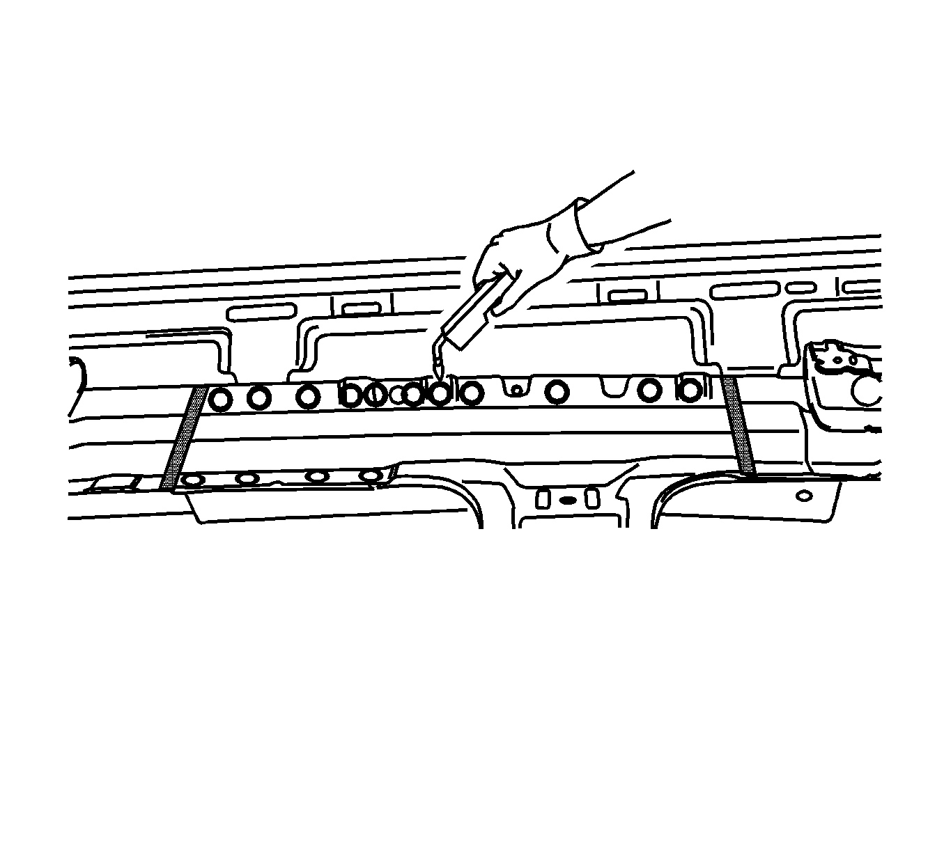

Note: If installing a new door sealing strip frame, drill 8 mm (5/16 in) plug weld holes as noted from original panel.
