Removal Procedure
- Disable the supplemental inflatable restraint (SIR) system.
- Disconnect the negative battery cable.
- Remove all related panels and components.
- Restore as much of the damage as possible to factory specifications. Refer to Dimensions - Body.
- Note the location and remove the sealers and anti-corrosion materials from the repair area as necessary. Refer to Anti-Corrosion Treatment and Repair.
- Remove the door assembly from the vehicle.
- Mark the position of the hinge.
- Locate all factory welds.
- Carefully grind the weld (1) from around the body side door hinge.
- Remove the hinge and grind any remaining weld from the pillar surface in order to ensure a flush fit of the service hinge.
Warning: Refer to Approved Equipment for Collision Repair Warning in the Preface section.
Warning: Refer to Battery Disconnect Warning in the Preface section.
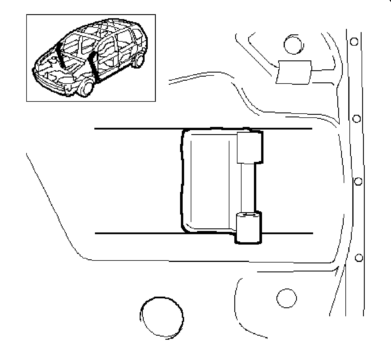
Note: Do not damage any inner panels or reinforcements.
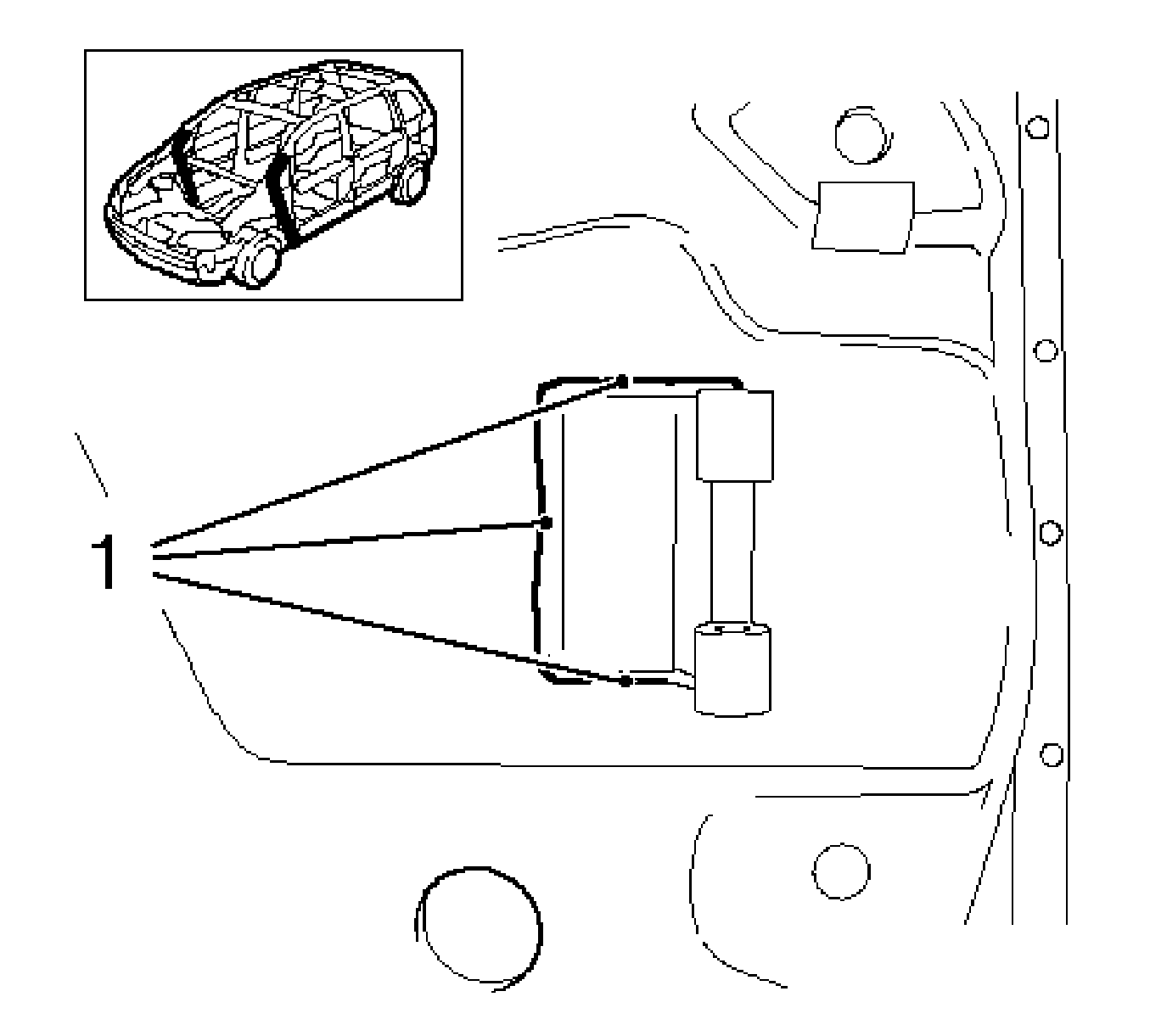
Installation Procedure
- Prepare all mating surfaces.
- Apply GM approved Weld-Thru coating or equivalent to all mating surfaces. Refer to Anti-Corrosion Treatment and Repair.
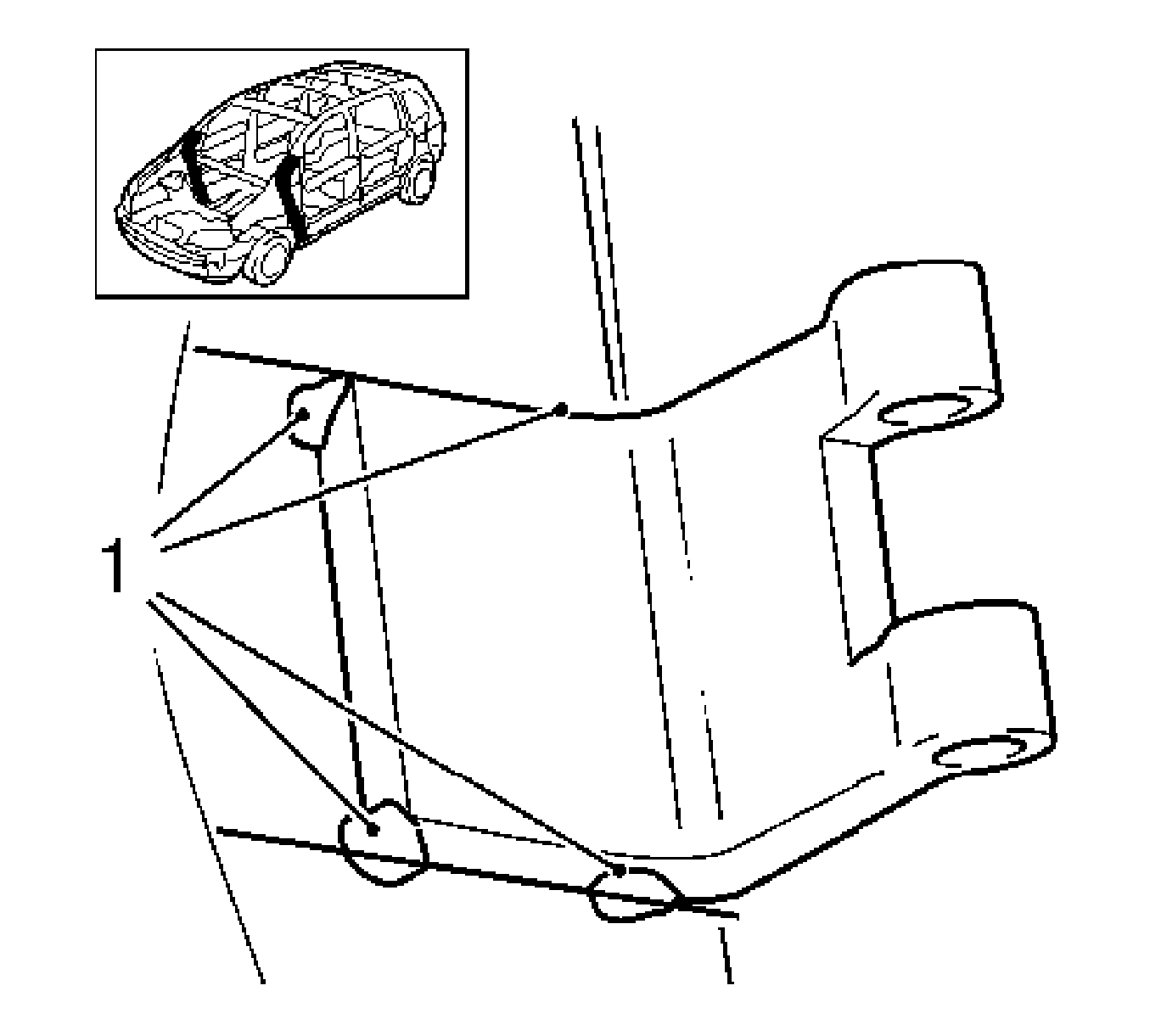
- Position the hinge with prior markings and secure with a suitable tool.
- MIG tack weld the hinge in the areas noted (1).
- With the aid of an assistant, position the door assembly to the door opening.
- Adjust the doors to the position as shown. (I & II) (2.0 +/- 0.5) mm. This increase will allow for the additional weight of the door hardware and trim components.
- Align door with the following gap specifications.
- Remove the door from the vehicle.
- Complete MIG welding doors hinges.
- Clean and prepare all welded surfaces.
- Apply the sealers and anti-corrosion materials to the repair area as necessary. Refer to Anti-Corrosion Treatment and Repair.
- Paint the repair area. Refer to Basecoat/Clearcoat Paint Systems.
- Install all related panel and components.
- Connect the negative battery cable.
- Enable the SIR system.
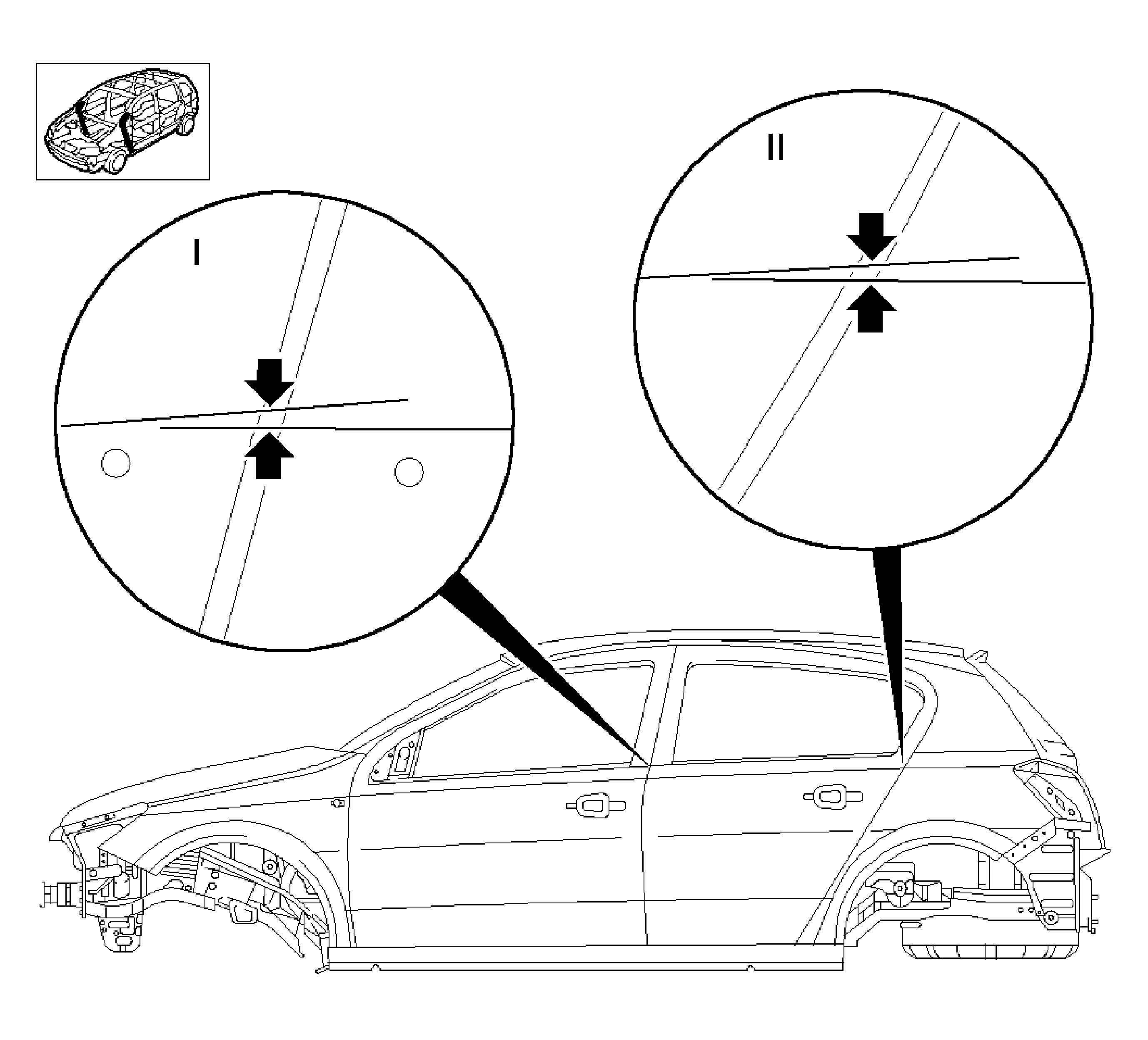
Note: The dimensions refer to unpainted doors before completion.
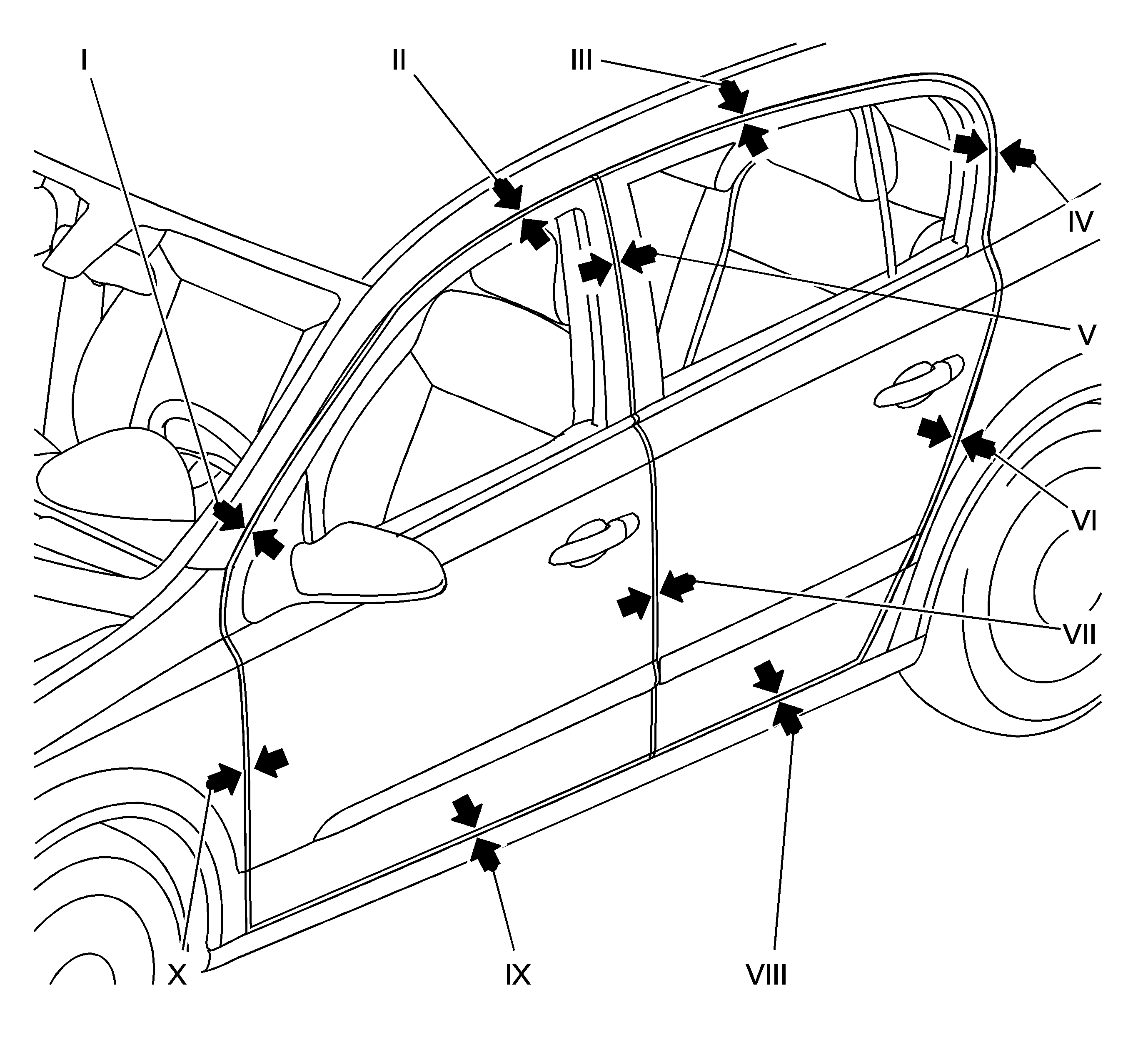
Note: The gap specifications refer to unpainted doors before completion with lock and striker installed but without door seals
| 7.1. | Position: I |
Dimensions in mm: 3.9
Tolerance in mm: +/- 1.0
| 7.2. | Position: II |
Dimensions in mm: 4.5
Tolerance in mm: +/- 1.0
| 7.3. | Position: III |
Dimensions in mm: 4.5
Tolerance in mm: +/- 1.0
| 7.4. | Position: IV |
Dimensions in mm: 4.0
Tolerance in mm: +/- 1.0
| 7.5. | Position: V |
Dimensions in mm: 3.8
Tolerance in mm: +/- 0.8
| 7.6. | Position: VI |
Dimensions in mm: 3.8
Tolerance in mm: +/- 0.8
| 7.7. | Position: VII |
Dimensions in mm: 3.8
Tolerance in mm: +/- 0.8
| 7.8. | Position: VIII |
Dimensions in mm: 4.5
Tolerance in mm: +/- 1.0
| 7.9. | Position: IX |
Dimensions in mm: 4.5
Tolerance in mm: +/- 1.0
| 7.10. | Position: X |
Dimensions in mm: 3.8
Tolerance in mm: +/- 0.8
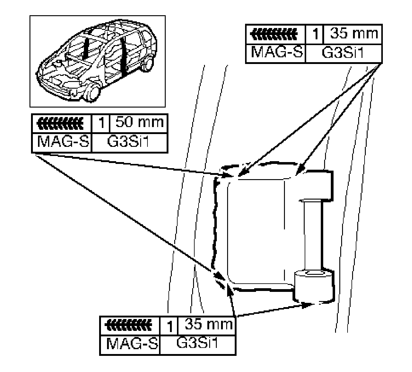
Note: To create a solid weld with minimum heat distortion, make a 25 mm (1 inch) stitch weld with 25 mm gaps between. Then go back and complete a solid weld seam.
