Removal Procedure
Caution: Refer to Battery Disconnect Warning in the Preface section.
Note: When replacing the control unit, before removing, carry out a Reset using the Tech 2. Refer to
Control Module References.
- Disconnect the battery.
- Remove the steering wheel. Refer to
Steering Wheel Replacement.

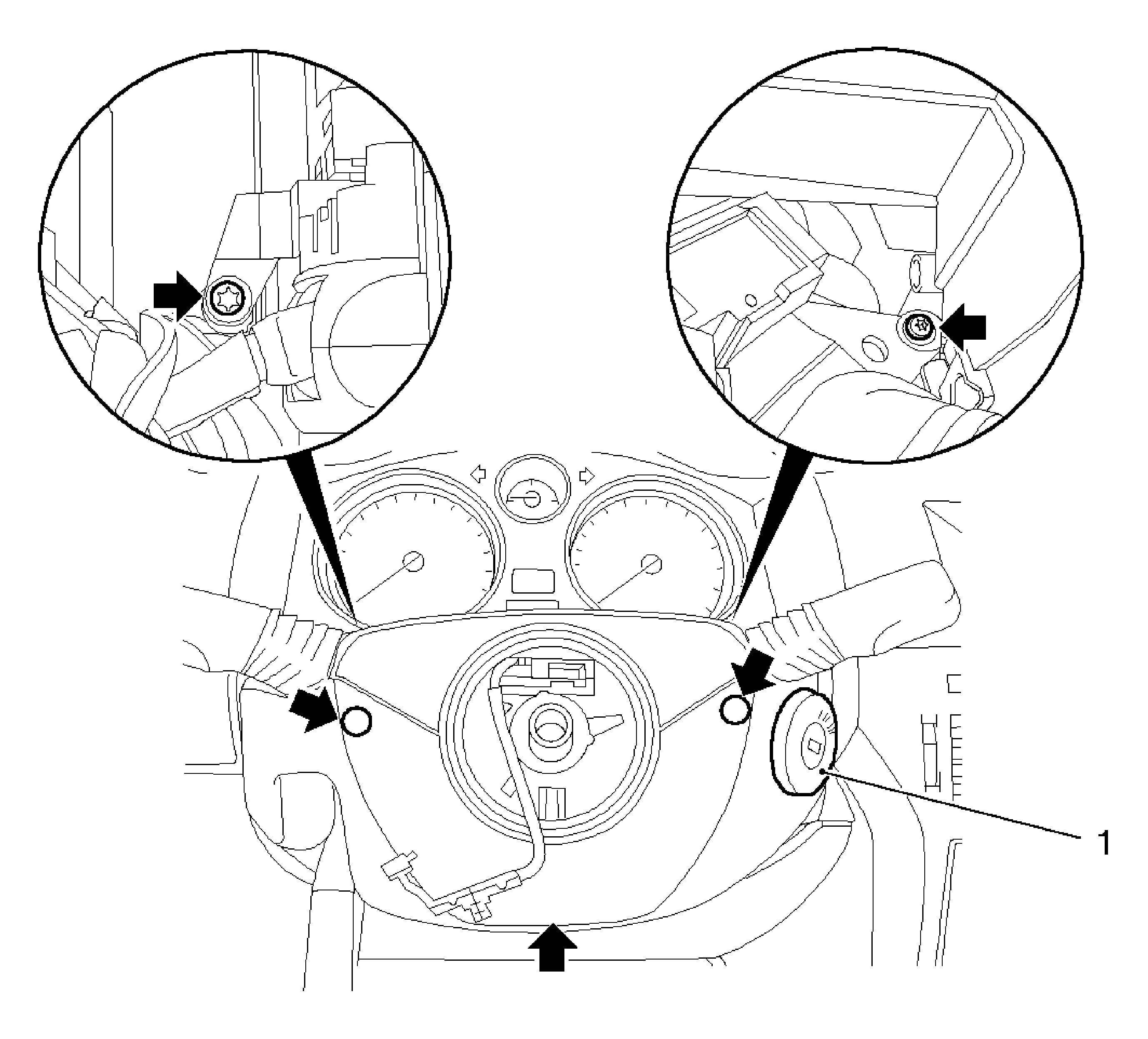
- Remove the lower steering column paneling.
| • | Remove the 5 bolts (arrows). |
| • | Remove the ignition lock panel (1). |
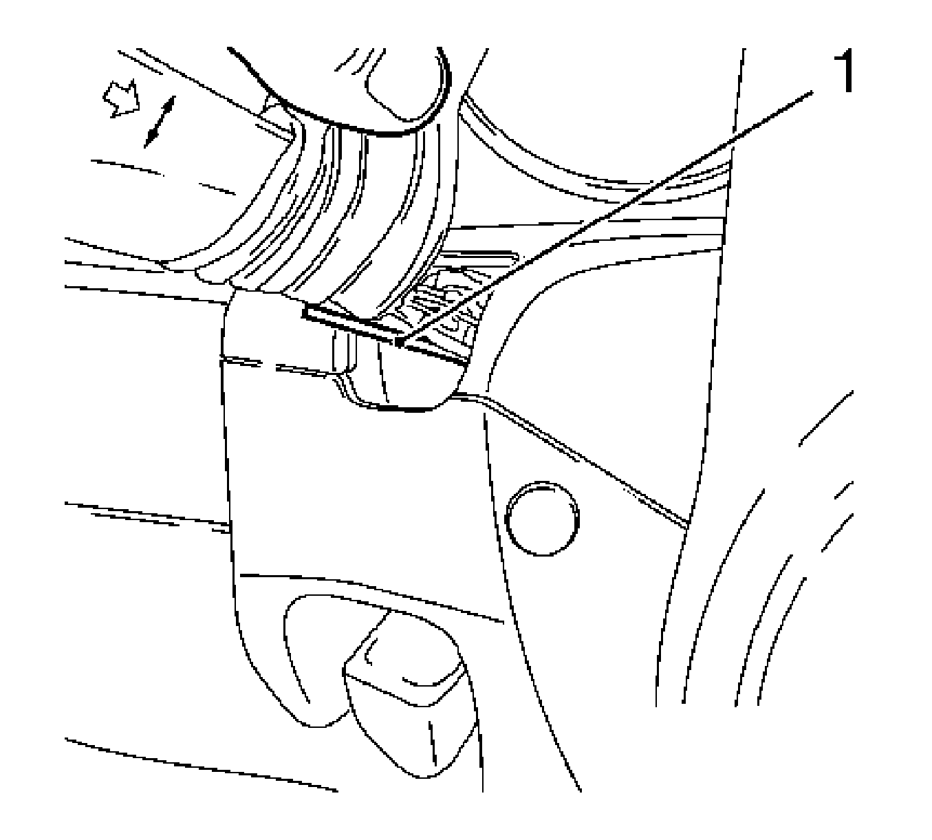
| • | Remove the rubber sleeve out of the steering column paneling. |

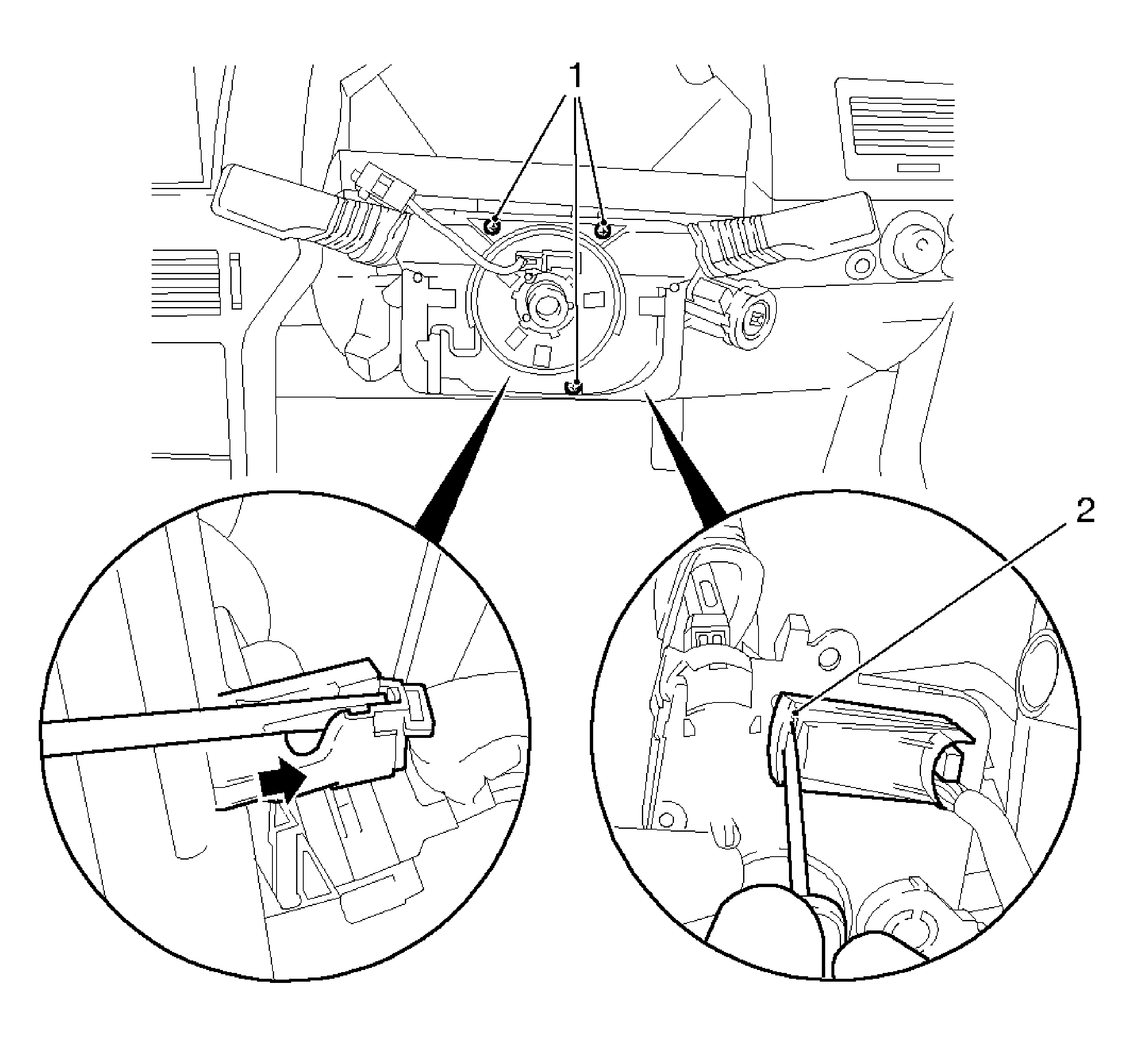
- Remove the column integration module (CIM).
| • | Remove the 3 bolts (1). |
| • | Remove the wiring harness holder (arrow). |
| • | Release the wiring harness plug (2) and disconnect. |

Note: Disconnect the engaging lug with a suitable tool (1), a hex screwdriver 1.5 mm WAF.
- Remove the turn signal multifunction switch.
| • | Remove the retaining lug. |
| • | Remove the actuating lever. |

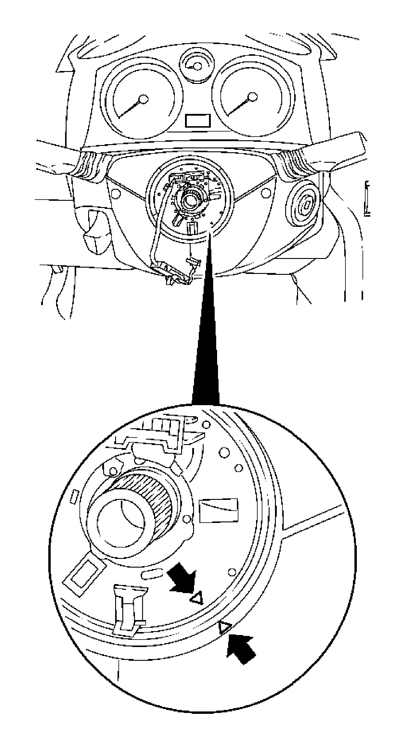
Note:
| • | The CIM replaces the existing contact unit and contains additional functions. |
| • | The contact unit may not be twisted when it has been removed. |
| • | When removing and installing, ensure that the markings (arrows) are opposite each other as shown in the illustration. |
- Remove the CIM.
Installation Procedure
Caution: Refer to Fastener Caution in the Preface section.
- Install the CIM.
| • | Connect and lock the wiring harness plug. |
| • | Install the wiring harness holder. |
Tighten
Tighten the 3 bolts to 3.5 N·m (32 lb in).
- Install the actuating lever.
| • | Engage the actuating lever. |
| • | Install the rubber sleeve in the steering column paneling. |
- Install the lower steering column paneling.
| • | Insert the ignition lock rosette. |
Tighten
Tighten the 5 screws to 1 N·m (9 lb in).
| • | Install the rubber sleeve in the steering column paneling. |
- Install the steering wheel. Refer to
Steering Wheel Replacement.
Note: When replacing the control unit, before removing, carry out a Reset using the Tech 2. Refer to
Control Module References.
- Connect the battery.
- For programming procedures, refer to
Control Module References.


