Removal Procedure
Note: When replacing the electrical center, before removing the control unit, carry out a "Reset" with TECH 2. Refer to Control Module References.
- Disconnect the battery.
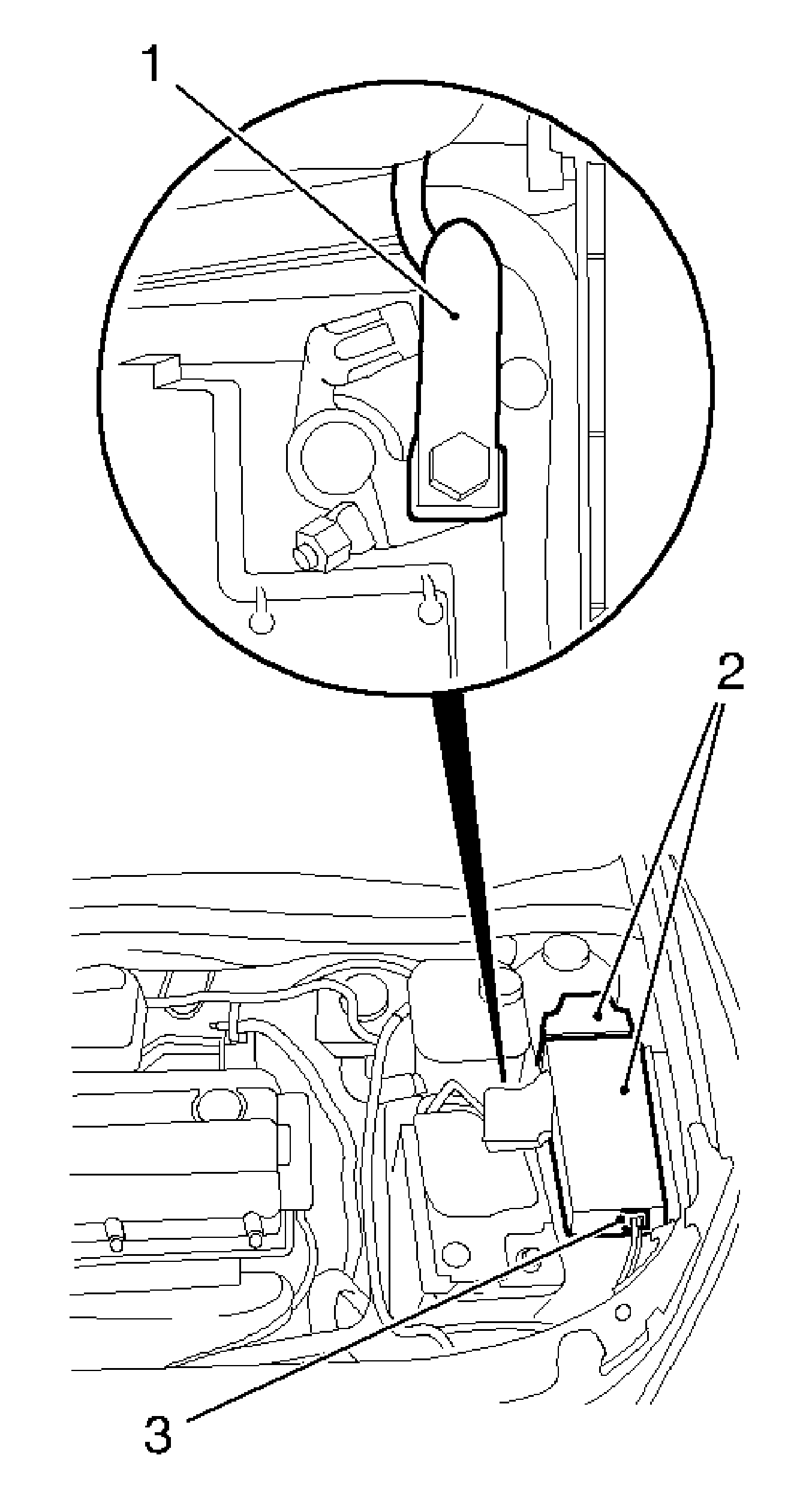
- Remove the wiring harness for positive distribution (1) from the positive terminal.
- Disconnect the compact plug (3).
- Remove the cover for the engine electrical center and the positive distribution (2).
- Release engine compartment electrical center.
- Remove the engine compartment electrical center.
Warning: Refer to Battery Disconnect Warning in the Preface section.
Disconnect the negative battery cable.

Remove the bolt.

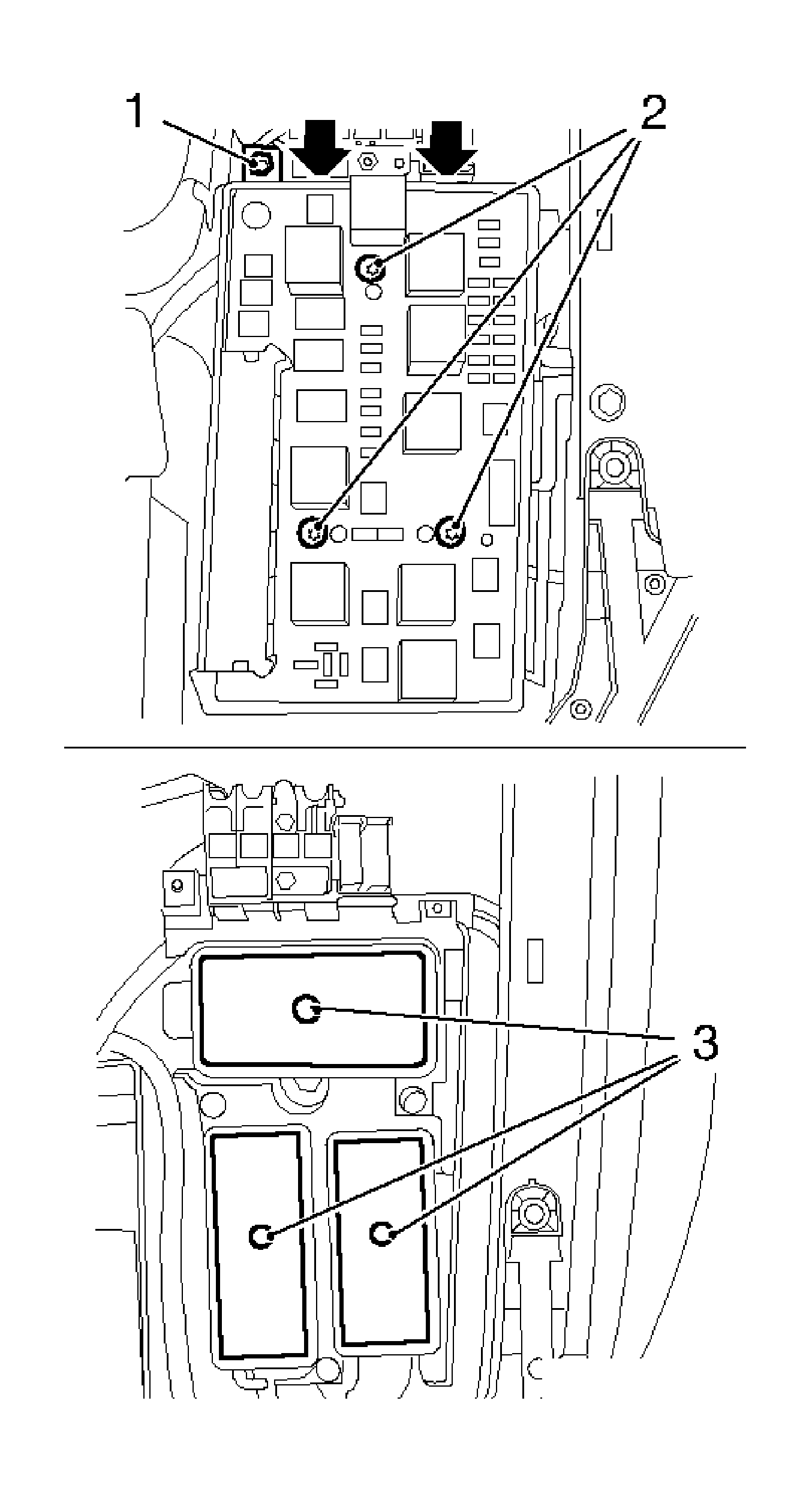
| • | Remove the 3 bolts (2). |
| • | Remove the nut (1) from the voltage supply. |
| • | Disconnect the 2 retaining lugs (arrow). |
Note:
• The screws (2) must be unscrewed until the wiring harness plugs (3) below the engine compartment electrical center can be unlocked. • Please pay attention to this when replacing the engine compartment electrical center. • The engine compartment electrical center contains the maximum number of relays and fuses. Some of these are surplus to requirements. Fuses F5 and F6 must be removed from the defective engine compartment electrical center and refitted. For fuse configuration.
Refer to
Master Electrical Component List.
Installation Procedure
- Insert the engine compartment electrical center.
- Install the engine compartment electrical center.
- Install the cover for the engine compartment electrical center and the positive distribution.
- Install the compact plug.
- Install the wiring harness for positive distribution to the positive terminal.
- Connect the battery.
- For programming procedures, refer to Control Module References.

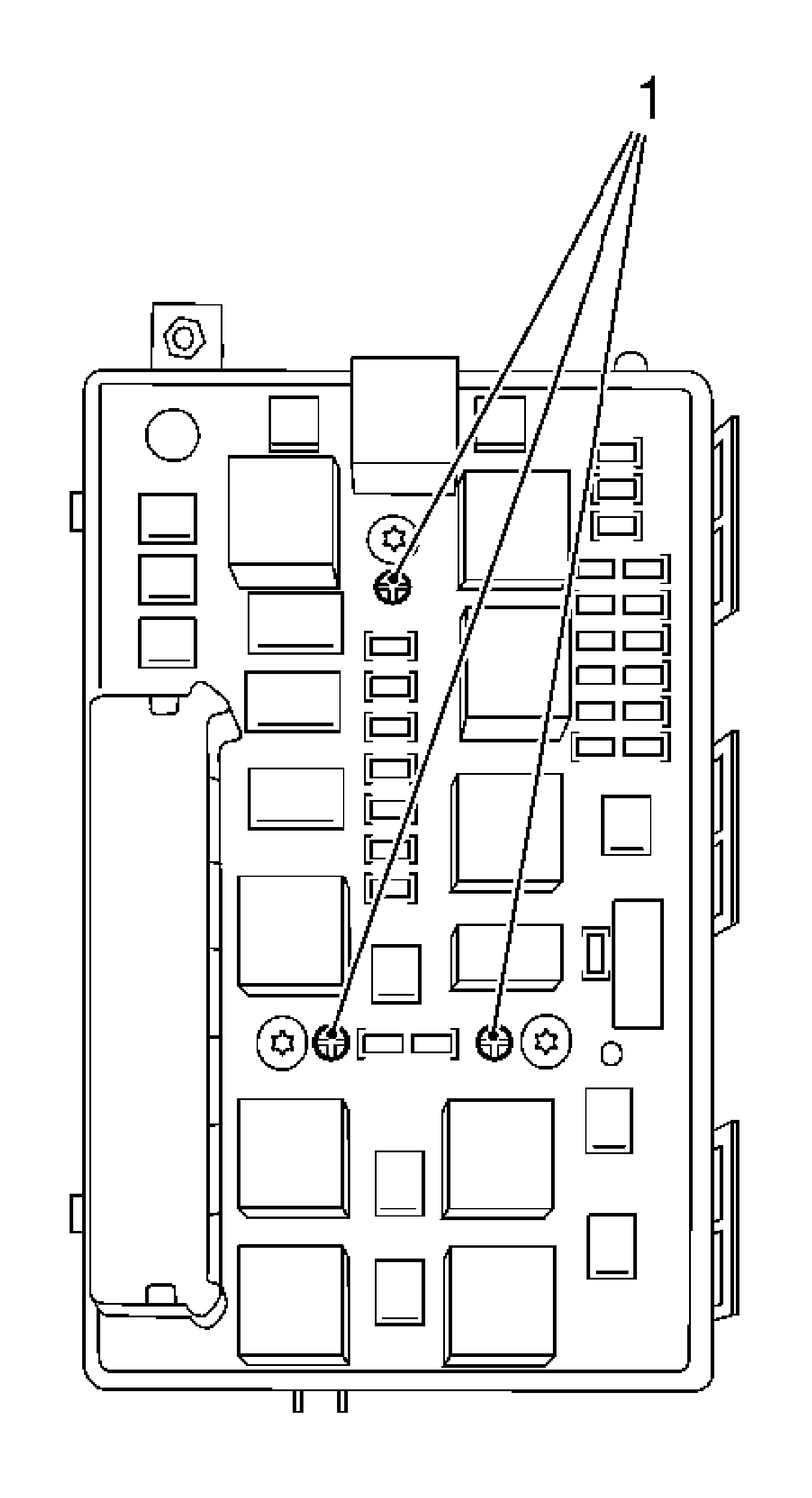
Note: Press the positioning pin (1) down to the stop with a suitable tool.
Caution: Refer to Fastener Caution in the Preface section.
Note: Positioning pins must be fully visible again when installed.
Install the 2 retaining lugs.
Tighten
| • | Tighten the 3 bolts to 6 N·m (53 lb in). |
| • | Tighten the voltage supply nut to 7 N·m (62 lb in). |
Tighten
Tighten the bolt to 10 N·m (89 lb in).
Connect the negative battery cable.
Note: When replacing the control unit, after fitting the control unit, carry out a Program with TECH 2. Refer to Control Module References.
