For 1990-2009 cars only
- Measure camber with computer-aided chassis alignment system.
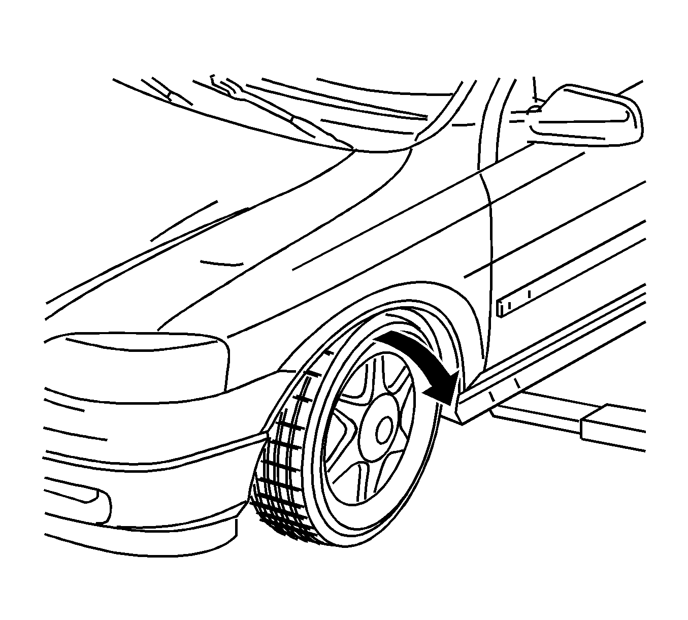
- Raise the vehicle at front.
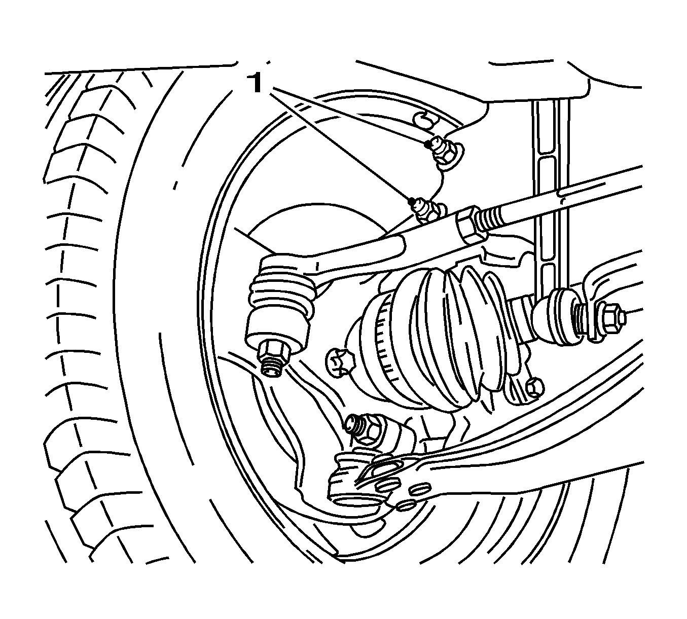
- Remove the 2 bolted connections (1), spring strut support tube to steering knuckle.
- Make the 2 bolted connections (1), spring strut support tube to steering knuckle.
- Pull the top of front wheel outwards (arrow) and adjust maximum positive camber.
- Tighten the 2 bolted connections, spring strut support tube to steering knuckle.
- Adjust the camber.
- Rock the vehicle several times.
- Inspect the camber setting again.
Note: The camber can only be set within a very limited range by the measures described below.
Note: The relevant front wheel must be freely suspended.
| • | Use the 2 new bolts. |
| • | Install the 2 new nuts. |
Caution: Refer to Fastener Caution in the Preface section.
Note: Tighten with reduced torque to create clamping effect between spring strut and steering knuckle.
Tighten
Tighten the bolted connections to 10 N·m (89 lb in).
Note: Camber changes in "negative" direction - move front wheel by hand if necessary.
| • | Slowly lower the vehicle onto the wheels. |
| • | Refer to Wheel Alignment Specifications. |
| • | When the specification has been achieved, tighten the 2 bolted connections, spring strut support tube to steering knuckle in 3 stages. |
Tighten
| • | Tighten the 2 bolted connections 50 N·m (37 lb ft). |
| • | Tighten the 2 new screwed joint 85 N·m (63 lb ft). |
| • | Continue to tighten the 2 new screw connection 75 degrees plus 15 degrees. |