For 1990-2009 cars only
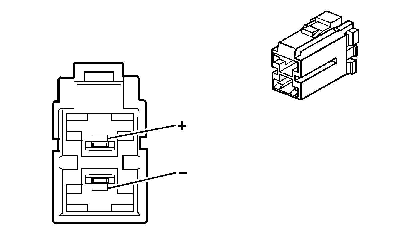
| Table 1: | Electronic Power Steering (EPS) Assembly C1 |
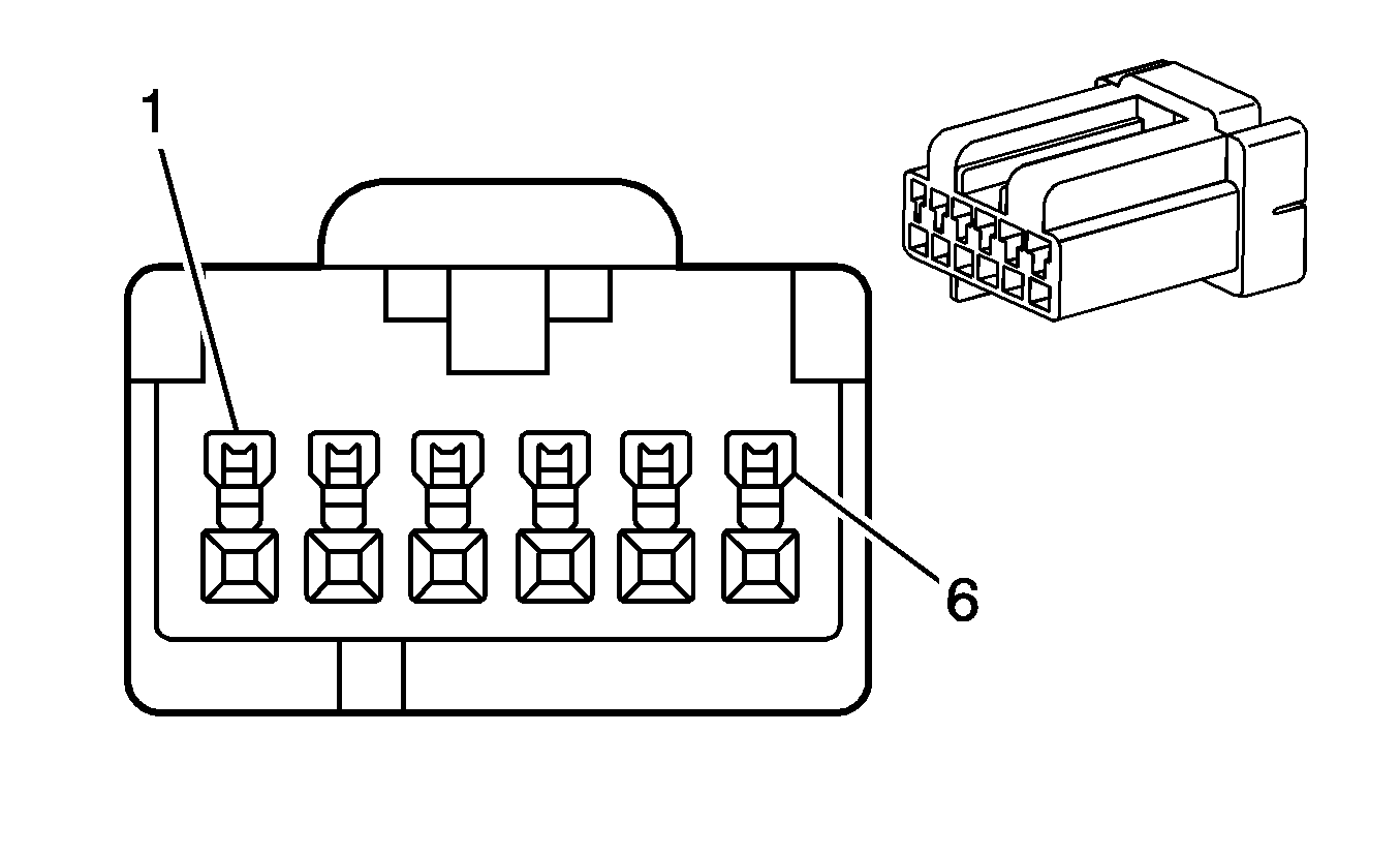
| Table 2: | Electronic Power Steering (EPS) Assembly C2 |
| Table 3: | Electronic Power Steering (EPS) Assembly C3 |

| |||||||
|---|---|---|---|---|---|---|---|
Connector Part Information |
| ||||||
Pin | Wire Color | Circuit No. | Function | ||||
+ | RD | 642 | Battery Positive Voltage | ||||
- | BK | 350 | Ground | ||||

| |||||||
|---|---|---|---|---|---|---|---|
Connector Part Information |
| ||||||
Pin | Wire Color | Circuit No. | Function | ||||
1-3 | -- | -- | Not Used | ||||
4 | VT | 1807 | Class 2 Serial Data | ||||
5 | VT | 1807 | Class 2 Serial Data | ||||
6 | PK | 1539 | Ignition 1 Voltage | ||||

| |||||||
|---|---|---|---|---|---|---|---|
Connector Part Information |
| ||||||
Pin | Wire Color | Circuit No. | Function | ||||
+ | RD | -- | Motor Control | ||||
- | BK | -- | Motor Control | ||||
