Removal Procedure
- Disable the SIR system. Refer to SIR Disabling and Enabling and SIR Disabling and Enabling in SIR.
- Remove the body control module (BCM). Refer to Body Control Module Replacement in Body Control System.
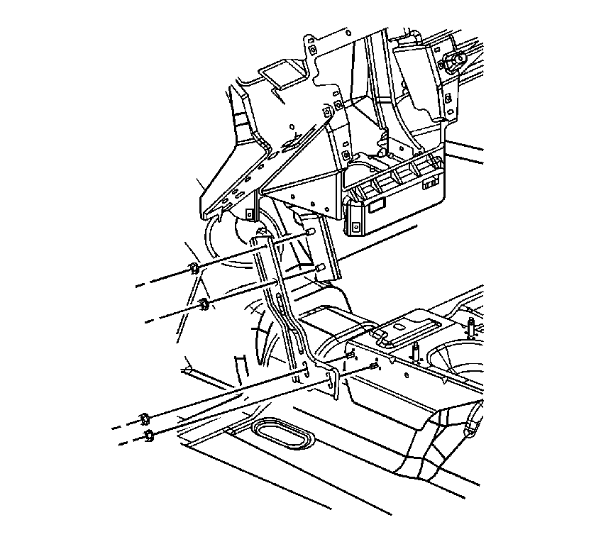
- Pull back the carpet at the bottom of the left center support bracket and remove the lower nuts from the bracket.
- Remove the nuts from the center support bracket and remove the bracket.
- Remove the defroster grille. Refer to Defroster Grille Replacement .
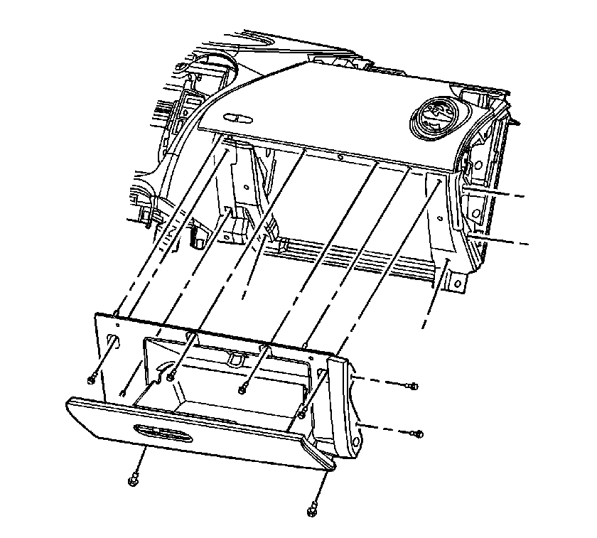
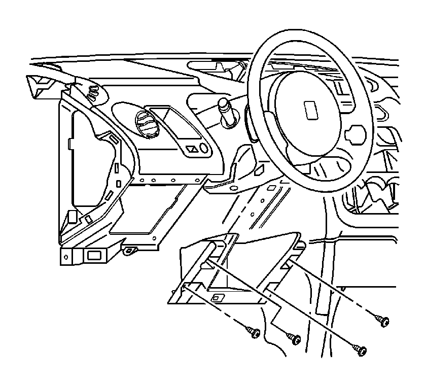
- Open the instrument panel (I/P) compartment.
- Remove the I/P compartment screws.
- Remove the I/P compartment by pulling outward.
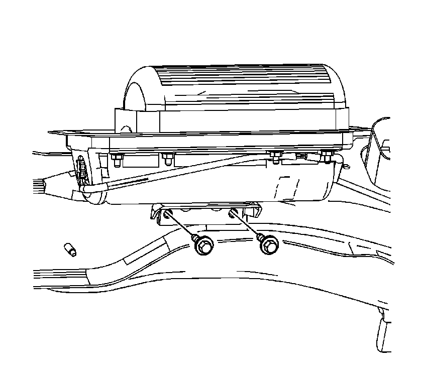
- Remove the bolts from the I/P inflatable restraint module.
- Slide the restraint module down and rearward to allow clearance for the I/P trim panel bracket.
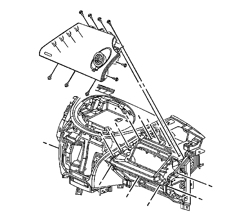
- Remove the screws from the right I/P trim panel.
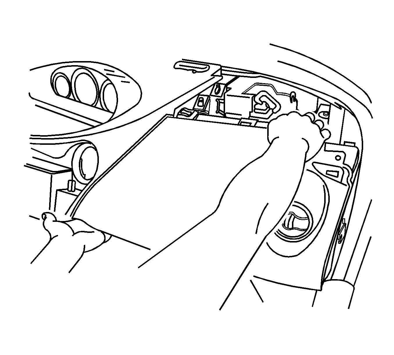
- Push on the upper right corner of the trim panel while lifting up on the lower left corner, to release the retaining clips and disengage the trim panel bracket from the I/P retainer.
- Remove the trim panel by pulling upward.
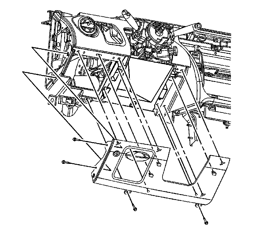
- Remove the screws from the steering column filler panel.
- Pull out on the filler panel in order to release the retaining fasteners.
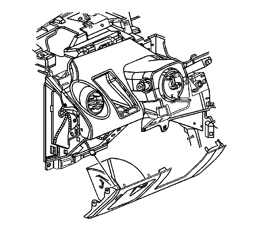
- Disconnect the electrical connector from the rear compartment release switch.
- Remove the I/P lower compartment screws and remove the compartment.
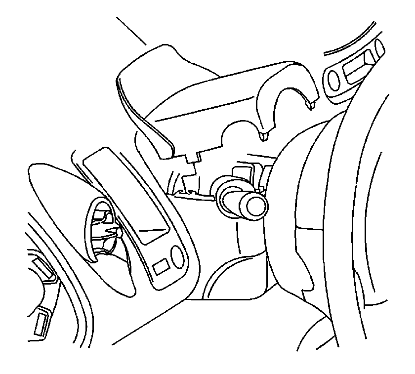
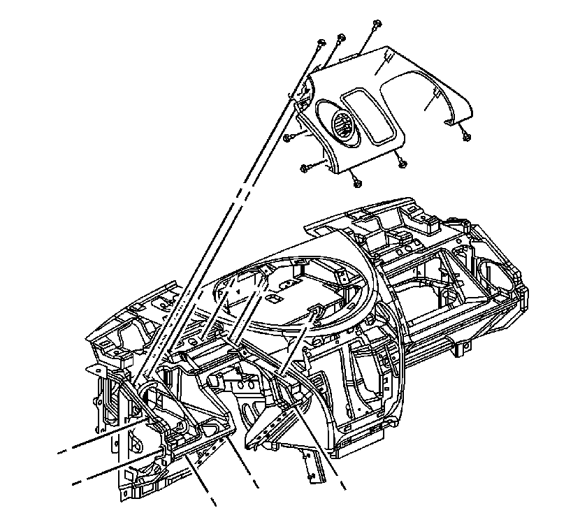
- Unsnap and remove the upper steering column cover.
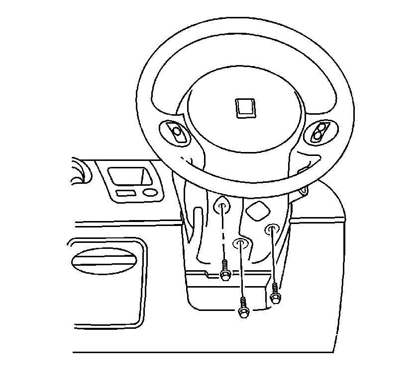
- Remove the screws from the lower steering column cover.
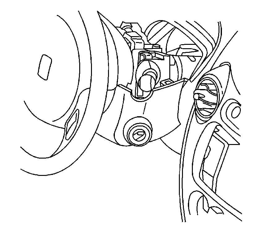
- Lower the steering column adjusting handle.
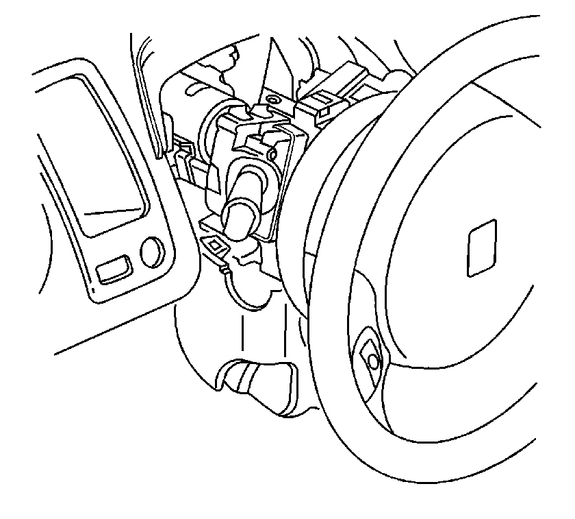
- Unsnap and remove the left lower steering column cover.
- Remove the right lower steering column cover.
- Remove the screws from the left I/P trim panel.
- Pull up on the trim panel in order to release the retaining fasteners.
- Disconnect the electrical connector from the I/P dimmer switch.
- If equipped, disconnect the fog lamp switch connector.
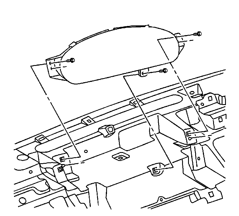
- Remove the cluster screws.
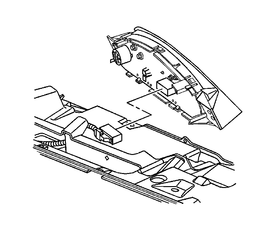
- Pull the cluster out and disconnect the electrical connector.
- Remove the cluster from the vehicle.
- Remove the screws from the I/P center trim panel and remove the trim panel.
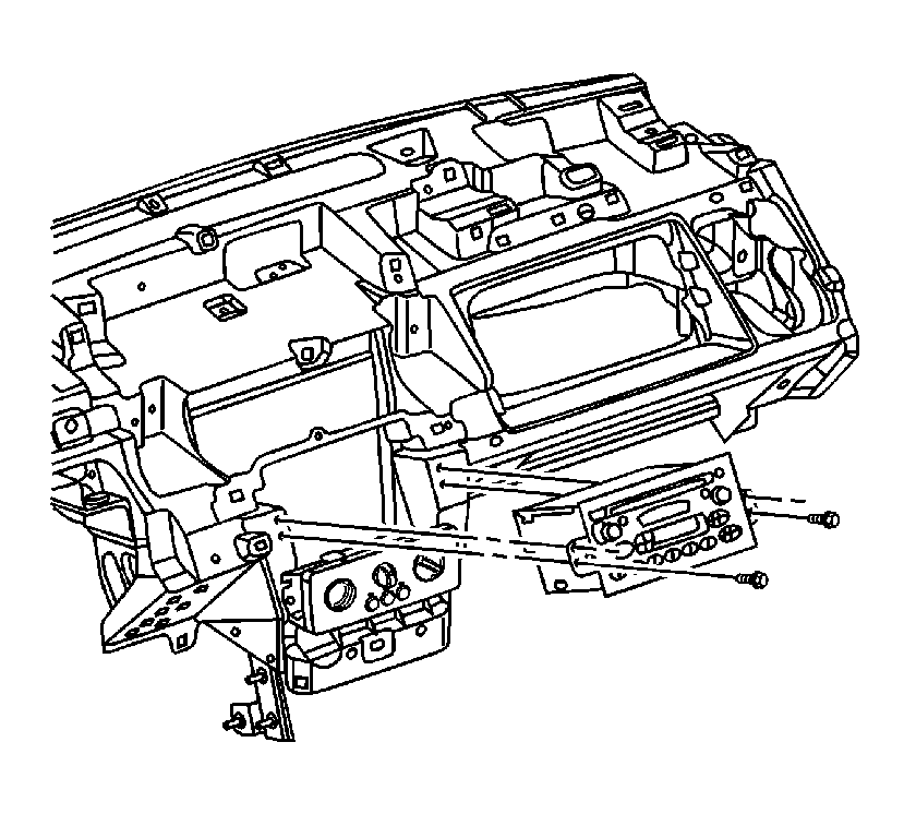
- Remove the screws from the radio and pull the radio out.
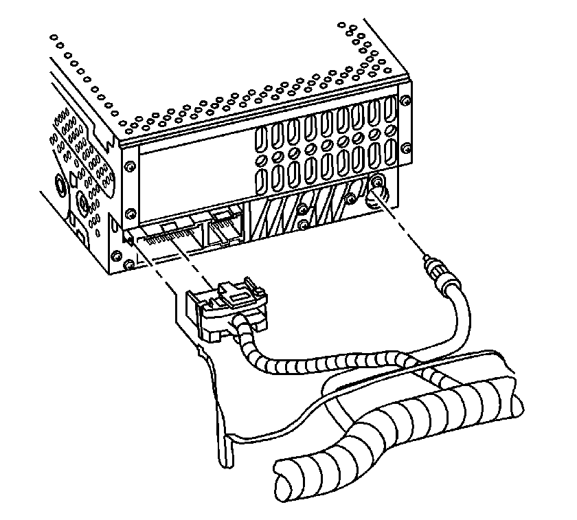
- Disconnect the radio electrical connectors and remove the radio.
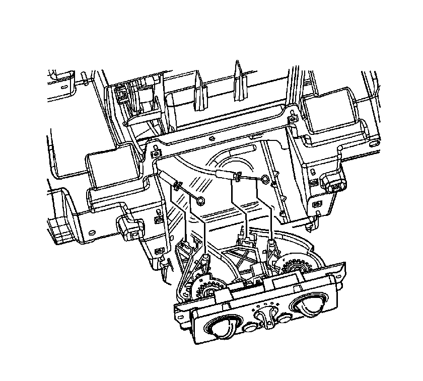
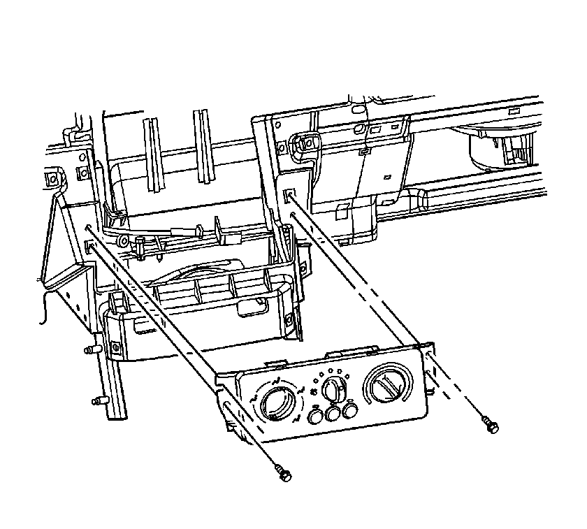
- Disconnect the mode and temperature cables from the HVAC control assembly.
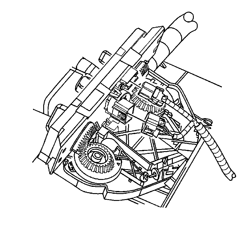
- Disconnect the HVAC control assembly electrical connectors.
- Remove the screws from the HVAC control assembly and remove the assembly.
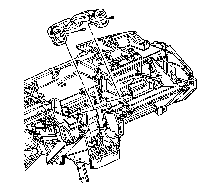
- Remove the screws from the center air outlet duct and remove the duct.
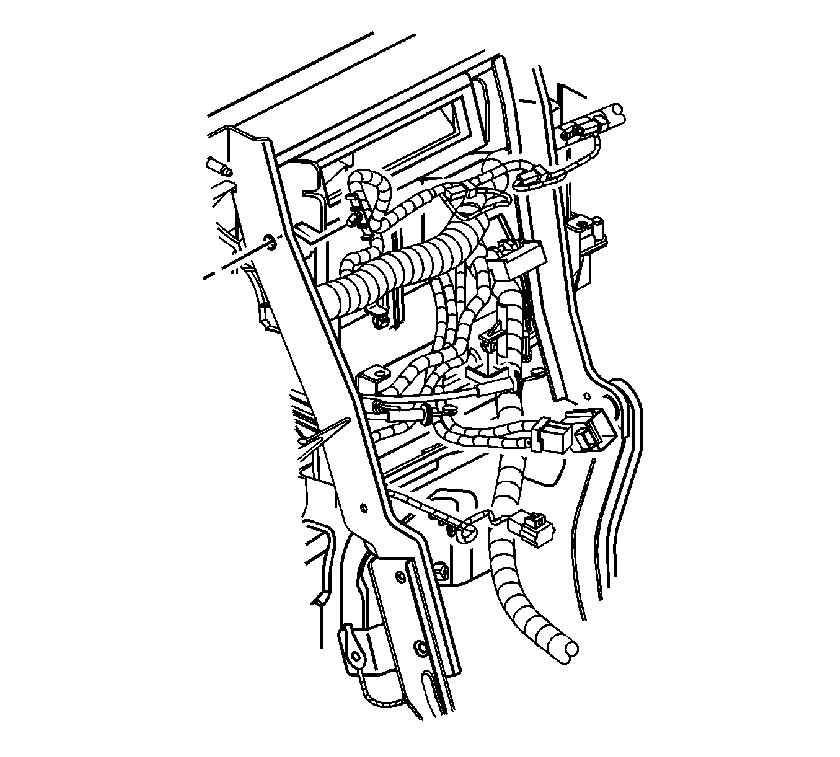
- Remove the wire rosebuds for the accessory switch harness from the I/P retainer.
- Remove the screws from the left outer air outlet duct and remove the duct.
- Remove the screws from the right outer air outlet duct and remove the duct.
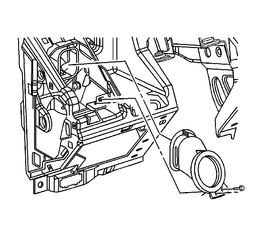
- Remove the defroster duct screw.
- Remove the wire rosebuds for the I/P inflatable restraint from the I/P retainer bracket.
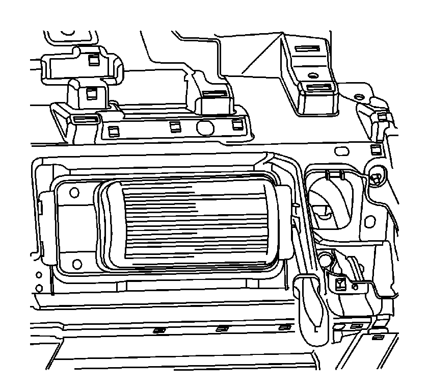
- Use a flat-bladed tool to depress one of the retaining tabs on the I/P retainer and pull the inflatable restraint module out of the retainer.
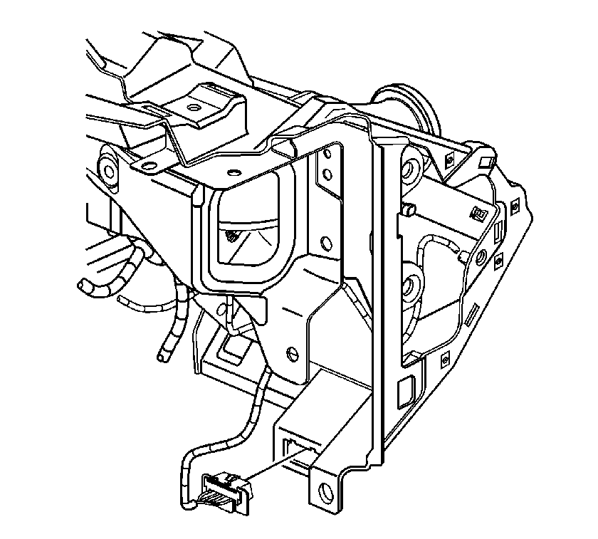
- Unsnap the DLC connector from the I/P retainer.
- Remove the left and the right front carpet retainers. Refer to Front Carpet Retainer Replacement in Interior Trim.
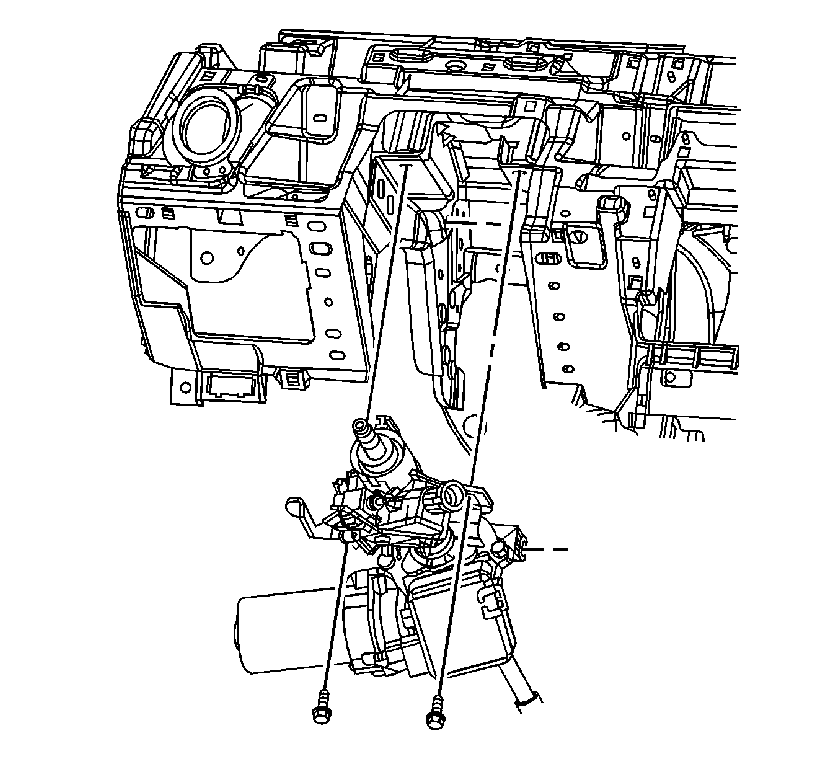
- Position the steering column to the highest position and remove the rear steering column bolts.
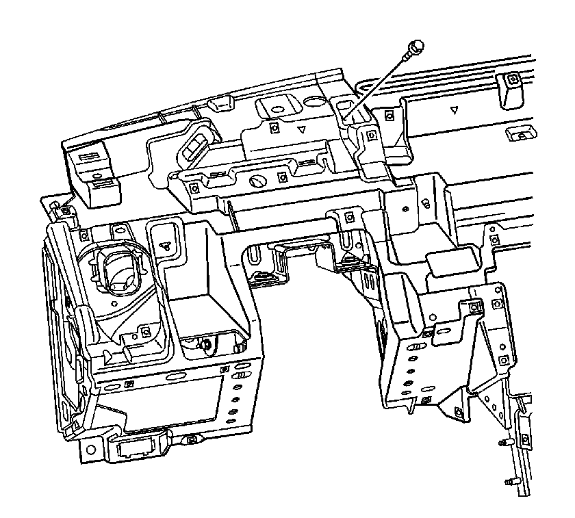
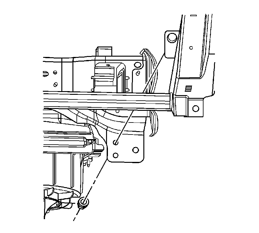
- Remove nut which secures the I/P retainer to the I/P carrier on the lower right side of the I/P retainer.
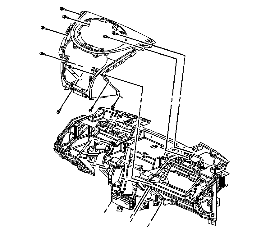
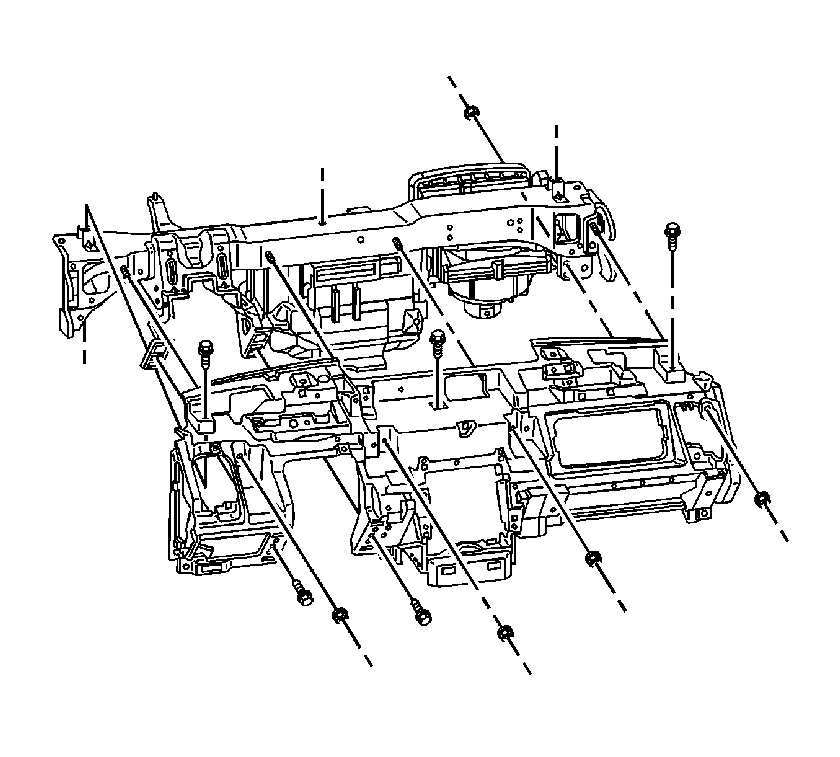
- Remove the remaining I/P retainer fasteners.
- Remove the I/P retainer by sliding the retainer along the steering column support bracket and toward the right side of the vehicle until the retainer clears the steering wheel.
Caution: Refer to SIR Inflator Module Handling and Storage Caution in the Preface section.
Caution: Refer to SIR Caution in the Preface section.
Caution: A deployed dual stage inflator module will look the same whether one or both stages were used. Always assume a deployed dual stage inflator module has an active stage 2. Improper handling or servicing can activate the inflator module and cause personal injury.
Installation Procedure
- Install the I/P retainer into the right side of the vehicle. Lift the I/P retainer above the steering wheel and slide the retainer down along the steering column support bracket.
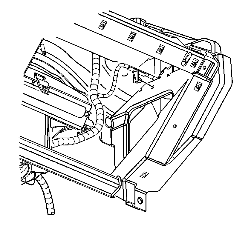
- Feed the HVAC control cables and the I/P harness connectors through the center of the I/P retainer. Align the I/P retainer with the studs on the I/P carrier beam and slide the I/P retainer into position.
- Install the I/P retainer nuts.
- Install the I/P retainer bolts.
- Install the I/P retainer screws.
- Install the nut which secures the I/P retainer to the I/P carrier. Place the nut facing forward in the vehicle on the lower right side of the I/P retainer.
- Raise the steering column into position and install the rear steering column bolts.
- Install the left and right front carpet retainers. Refer to Front Carpet Retainer Replacement in Interior Trim.
- Snap the DLC connector into the I/P retainer.
- Install the I/P inflatable restraint module into the I/P retainer.
- Install the wire rosebuds for the I/P inflatable restraint module to the I/P retainer bracket.
- Install the defroster duct screw.
- Install the left outer air outlet duct and screw.
- Install the right outer air outlet duct and screw.
- Install the rosebuds for the accessory switch wire harness to the I/P retainer.
- Install the center air outlet duct and screws.
- Install the HVAC control assembly and screws.
- Connect the mode and temperature cables to the HVAC control assembly.
- Connect the electrical connectors to the HVAC control assembly.
- Place the radio in the vehicle and connect the radio electrical connectors.
- Push the radio into position and install the screws.
- Install the I/P center trim panel and screws.
- Position the cluster in the vehicle and connect the cluster electrical connector.
- Install the cluster screws.
- Place the left I/P trim panel into the vehicle.
- Connect the electrical connector to the I/P dimmer switch.
- If equipped, connect the fog lamp switch connector.
- Align the I/P trim panel retaining fasteners with the I/P.
- Push on the I/P trim panel in order to secure the retaining fasteners.
- Install the I/P trim panel screws.
- Install the right lower steering column cover.
- Install the left lower steering column cover and snap the 2 covers together.
- Raise the steering column adjusting handle to lock the steering column into place.
- Install the screws to the lower steering column cover.
- Install the upper steering column cover by guiding the soft closeout under the I/P trim panel and aligning the retaining fasteners with the lower covers.
- Push on the upper steering column cover to secure the column in place.
- Install the I/P lower compartment and the screws.
- Place the steering column filler panel in the vehicle and connect the electrical connector to the rear compartment release switch.
- Align the retaining fasteners with the I/P.
- Push the filler panel in order to secure.
- Install the filler panel screws.
- Verify that the retaining clips are installed on the right I/P trim panel and that no clips are remaining in the I/P center trim panel.
- Place the right I/P trim panel in the vehicle and align the locating pins and the retaining clips with the I/P. Push on the I/P trim panel in order to secure.
- Pull up on the upper edge of the trim panel to verify that the bracket is hooked onto the I/P retainer.
- Install the I/P trim panel screws.
- Slide the I/P inflatable restraint module up into position.
- Install the bolts to the I/P inflatable restraint module.
- Place the I/P compartment in the vehicle and align the locating pins with the I/P.
- Push on the I/P compartment in order to secure.
- Install the I/P compartment screws.
- Install the defroster grille. Refer to Defroster Grille Replacement .
- Pull back the carpet and position the left center support bracket into position.
- Install the center support bracket nuts.
- Install the body control module. Refer to Body Control Module Replacement in Body Control Systems.
- Enable the SIR system. Refer to SIR Disabling and Enabling and SIR Disabling and Enabling in SIR.

Important: Do not bend the HVAC control cable when installing the I/P retainer.
Notice: Refer to Fastener Notice in the Preface section.
Tighten
Tighten the nuts to 10 N·m (88 lb in).
Tighten
Tighten the bolts to 10 N·m (88 lb in).
Tighten
Tighten the screws to 2.5 N·m (22 lb in).

Tighten
Tighten the nut to 10 N·m (88 lb in).

Tighten
Tighten the bolts to 25 N·m (18 lb ft).


Do NOT install the restraint module bolts until after you have installed the right I/P trim panel.


Tighten
Tighten the screw to 2.5 N·m (22 lb in).

Tighten
Tighten the screw to 2.5 N·m (22 lb in).
Tighten
Tighten the screw to 2.5 N·m (22 lb in).


Tighten
Tighten the screws to 2.5 N·m (22 lb in).

Tighten
Tighten the screws to 2.5 N·m (22 lb in).


Tighten
Tighten the radio screws to 2.5 N·m
(22 lb in).

Tighten
Tighten the screws to 2.5 N·m (22 lb in).


Tighten
Tighten the cluster screws to 2.5 N·m
(22 lb in).

Tighten
Tighten the screws to 2.5 N·m (22 lb in).


Tighten
Tighten the screws to 2 N·m (17 lb in).


Tighten
Tighten the screws to 2.5 N·m (22 lb in).


Tighten
Tighten the screws to 2.5 N·m (22 lb in).

Tighten
Tighten the screws to 2.5 N·m (22 lb in).

Tighten
Tighten the bolts to 10 N·m (88 lb in).

Tighten
Tighten the screws to 2.5 N·m (22 lb in).

Tighten
Tighten the nuts to 10 N·m (88 lb in).
