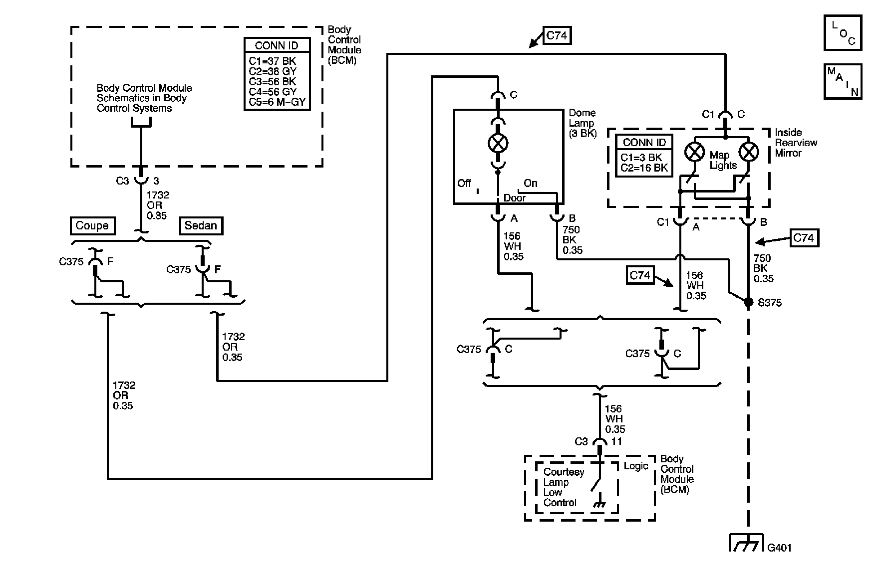
Circuit Description
When the headlamp switch is turned to the PARK or HEAD position, the body control module (BCM) applies battery positive voltage to the I/P courtesy lamps. When a door is opened, the door latch assembly applies a ground to the BCM. The BCM supplies battery positive voltage to the courtesy lamp supply voltage circuit and applies a ground to the courtesy lamps low control circuit.
Conditions for Running the DTC
At least one of the following conditions must exist:
| • | At least one door is open. |
| • | The interior lamps are commanded on by the BCM. |
Conditions for Setting the DTC
| • | The interior lamps are commanded on by the BCM. |
| • | The interior lamp control circuit is shorted to battery positive voltage for 0.1 seconds. |
Action Taken When the DTC Sets
| • | DTC B2558 is stored in the BCM memory. |
| • | The BCM disables the interior lamp control output for the remainder of the ignition cycle. |
Conditions for Clearing the DTC
| • | The conditions for setting the DTC are no longer present. |
| • | A history DTC clears after 100 malfunction free ignition cycles. |
| • | The BCM receives the clear code command from the scan tool. |
Diagnostic Aids
| • | If the DTC is a history DTC, the problem may be intermittent. Refer to Testing for Intermittent Conditions and Poor Connections in Wiring Systems. |
| • | The following conditions may cause an intermittent malfunction to occur: |
| - | An intermittent in the courtesy lamp low control circuit. |
| - | The BCM is intermittently shorted to battery positive voltage. |
Step | Action | Yes | No |
|---|---|---|---|
Schematic Reference: Interior Lights Schematics Connector End View Reference: Master Electrical Component List in Wiring Systems | |||
1 | Did you perform the Lighting System Diagnostic System Check? | Go to Step 2 | |
2 |
Do the courtesy lamps turn ON and OFF with each command? | Go to Testing for Intermittent Conditions and Poor Connections in Wiring Systems | Go to Step 3 |
3 |
Does the test light illuminate? | Go to Step 5 | Go to Step 4 |
4 | Inspect for poor connections at the harness connector of the BCM. Refer to Testing for Intermittent Conditions and Poor Connections and Connector Repairs in Wiring Systems. Did you find and correct the condition? | Go to Step 7 | Go to Step 6 |
5 | Repair the short to battery positive voltage in the courtesy lamp low control circuit. Refer to Circuit Testing and Wiring Repairs in Wiring Systems. Did you complete the repair? | Go to Step 7 | -- |
6 |
Important: Perform the setup procedure for the Body Control Module. Refer to Body Control Module (BCM) Programming/RPO Configuration in Body Control System. Replace the body control module. Refer to Body Control Module Replacement in Body Control System. Did you complete the replacement? | Go to Step 7 | -- |
7 |
Does the DTC reset? | Go to Step 2 | System OK |
