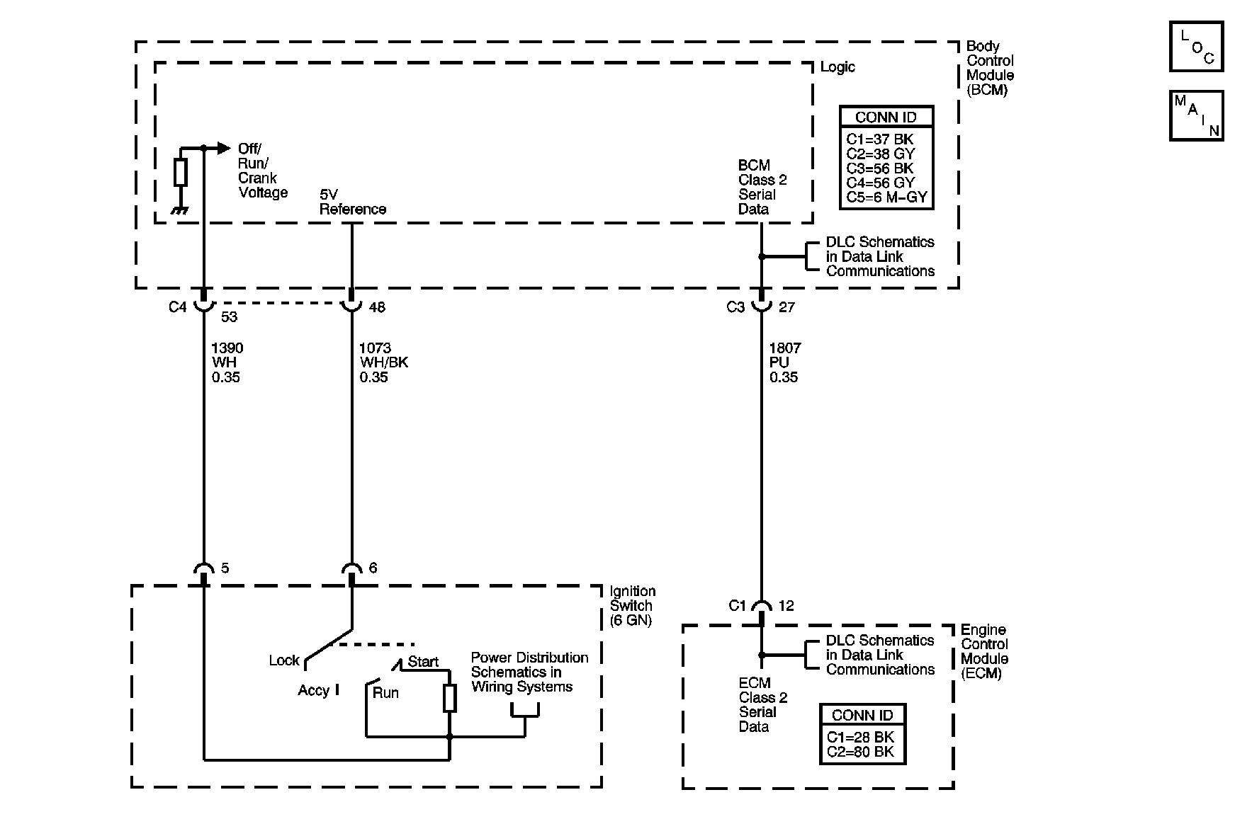
Circuit Description
The Passlock™ system is provided in order to prevent vehicle theft if the ignition lock cylinder is forced to rotate. The Passlock controller reads the coded Passlock™ data signal. The data consists of a voltage generated by a voltage divider network created between the Passlock assembly and the Passlock™ controller. If the data is correct , indicating rotation of the lock cylinder with the proper mechanically cut key, then the Passlock™ controller sends a password to the Powertrain controller over the class 2 bus to indicate that starter engagement should be allowed. The Passlock™ controller also interfaces with the driver displays subsystem to indicate, via a Security telltale, the Passlock™ subsystem's status and acute subsystem failures.
Conditions for Setting the DTC
| • | The BCM will inspect for a valid code when the ignition is rotated from ON to CRANK and will continue to monitor the signal during the engine running period. |
| • | The BCM is reading a valid but different code value than previously learned form the Passlock™ sensor. |
Action Taken When the DTC Sets
| • | The vehicle will not start if the fault occurs before you start the vehicle. The security indicator will be FLASHING. |
| • | If the vehicle is running when the fault occurs, the BCM will be in the fail enable mode allowing the vehicle to start and run. The security indicator will be ON. |
Conditions for Clearing the DTC
| • | The DTC will clear once an ignition cycle occurs without the fault recurring. |
| • | The BCM history codes will clear once 100 concurrent ignition cycles occur without the fault recurring. |
| • | Using a scan tool. |
Diagnostic Aids
| • | Use a scan tool in order to inspect the Passlock™ data voltage and the Passlock™ code. |
| • | Inspect for poor connections at the Passlock™ sensor. Refer to Testing for Intermittent Conditions and Poor Connections in Wiring Systems. |
Test Description
The number below refers to the step number on the diagnostic table.
Step | Action | Value(s) | Yes | No |
|---|---|---|---|---|
1 | Did you perform the Theft Deterrent (VTD) Diagnostic System Check? | -- | Go to Step 2 | |
2 |
Does the scan tool display DTC B2960 as a current DTC? | -- | Go to Step 3 | Go to Testing for Intermittent Conditions and Poor Connections in Wiring Systems |
3 | Does the scan tool display DTC B2947, B2948, B2957, or B2958? | -- | Go to Step 4 | |
4 | Have you replaced the Passlock™ sensor on this vehicle? | -- | Go to Step 5 | Go to Step 6 |
5 | Have you performed a Passlock™ learn procedure after replacing the Passlock™ sensor? | -- | Go to Step 6 | Go to Step 9 |
With a scan tool, observe the Passlock™ data voltage for one minute. Does the scan tool indicate that the Passlock™ data voltage is changing more than the specified value? | +/- 0.02 V | Go to Step 7 | Go to Step 9 | |
7 | Inspect for poor connections at the Passlock™ sensor. Refer to Testing for Intermittent Conditions and Poor Connections and Connector Repairs in Wiring Systems. Did you find and correct the condition? | -- | Go to Step 10 | Go to Step 8 |
8 | Replace the Passlock™ sensor. Refer to Ignition and Start Switch Replacement in Steering Wheel and Column. Did you complete the replacement? | -- | Go to Step 9 | -- |
9 | Perform the Programming Theft Deterrent System Components procedure. Is the repair complete? | -- | Go to Step 10 | -- |
10 |
Does the DTC reset? | -- | Go to Step 3 | System OK |
