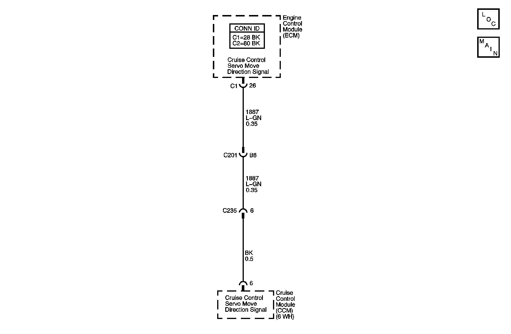
Circuit Description
To control which direction the cruise control module moves the accelerator pedal, the engine control module (ECM) commands the Cruise Control Servo Move Direction Signal circuit either high, wide open throttle (WOT) or low, idle. If the Cruise Servo Move Direction Signal circuit is commanded high and the ECM detects low feedback voltage, DTC P1582 will set.
Conditions for Running the DTC
Every time the Cruise Control Servo Move Direction Signal circuit is commanded high.
Conditions for Setting the DTC
| • | The ECM detects low feedback voltage when the Cruise Control Servo Move Direction Signal circuit is commanded high. |
| • | The condition exists for 500 ms. |
Action Taken When the DTC Sets
| • | The ECM stores the DTC information into memory when the diagnostic runs and fails. |
| • | The malfunction indicator lamp (MIL) will not illuminate. |
| • | The ECM records the operating conditions at the time the diagnostic fails. The ECM stores this information in the Failure Records. |
Conditions for Clearing the DTC
| • | A last test failed, or current DTC, clears when the diagnostic runs and does not fail. A new ignition cycle must take place before a test passed can be reported. |
| • | A history DTC will clear after 40 consecutive warm-up cycles, if no failures are reported by this or any other non-emission related diagnostic. |
| • | Use a scan tool in order to clear the DTC. |
Diagnostic Aids
Important:
• To locate an intermittent problem, use a scan tool to perform the Cruise
Control Cycle special function with the ignition ON, and the engine OFF. The accelerator
pedal should move to 50 percent throttle and then return to idle. If a short
to ground exists, the pedal will remain at rest or return to idle. • C/C Dir. Ckt.-Low Volt test can be monitored to aid in diagnosing an intermittent
fault. Monitor the test while tapping the Resume/Accel switch, this moves the throttle
toward WOT. If a fault exists, the scan tool will display Test Fail.
Test Description
The number below refers to the step number on the diagnostic table.
Step | Action | Yes | No |
|---|---|---|---|
Connector End View Reference: Cruise Control Connector End Views | |||
1 | Did you perform the Diagnostic System Check -- Cruise Control? | Go to Step 2 | |
Does the throttle angle reach 50% then return to idle? | Go to Diagnostic Aids | Go to Step 3 | |
3 |
Is ignition voltage present? | Go to Step 5 | Go to Step 4 |
4 | Inspect Cruise Control Servo Move Signal circuit for short to ground. Refer to Circuit Testing and Wiring Repairs in Wiring Systems. Did you find and correct the problem? | Go to Step 7 | Go to Step 6 |
5 | Replace the cruise control module. Refer to Cruise Control Module Replacement . Did you complete the repair? | Go to Step 7 | -- |
6 |
Important: The replacement ECM must be programmed. Replace ECM. Refer to Engine Control Module Replacement in Engine Controls. Did you complete the repair? | Go to Step 7 | -- |
7 |
Does the DTC reset? | Go to Step 2 | System OK |
